
XStream-PKG-R™ RS-232/485 RF Modem
XStream RS-232/485 RF Modem
Interfacing Protocol
RF Modem Operation
RF Modem Configuration
RF Communication Modes
Appendices
Product Manual v5.x00
For XStream RF Modem Part Numbers: X09-001PK…-R… X24-009PK…-R... XH9-001PK…-R...
X09-009PK…-R… X24-019PK…-R… XH9-009PK…-R…
X09-019PK…-R… XH9-019PK…-R…
900 MHz & 2.4 GHz Stand-alone RF Modems by MaxStream, Inc.
355 South 520 West, Ste. 180
Lindon, UT 84042
Phone: (801) 765-9885
Fax: (801) 765-9895
M100019
2006.02.24
www.maxstream.net

XStream‐PKG‐R™RS‐232/485RFModem–ProductManualv5.x00[2006.02.24]
© 2006 MaxStream, Inc. All rights reserved
Thecontentsofthismanualmaynotbetransmittedorreproducedin
anyformorbyanymeanswithoutthewrittenpermissionof
MaxStream,Inc.
XStream™isatrademarkofMaxStream,Inc.
TechnicalSupport
Phone:(801)765‐9885
LiveChat:
www.maxstream.net
E‐Mail:
rf‐[email protected]
©2006MaxStream,Inc.Confidential&Proprietary ii

XStream‐PKG‐R™RS‐232/485RFModem–ProductManualv5.x00[2006.02.24]
Contents
1. XStream RS-232/485 RF Modem 4
1.1. Features 4
1.1.1. Worldwide Acceptance 4
1.2. Specifications 5
1.3. External Interface 6
2. Interfacing Protocol 7
2.1. RS-232 Operation 7
2.1.1. DIP Switch Settings and Pin Signals 7
2.2. RS-485 (2-wire) Operation 9
2.2.1. DIP Switch Settings and Pin Signals 9
2.3. RS-485 (4-wire) & RS-422 Operation 10
2.3.1. DIP Switch Settings and Pin Signals 10
3. RF Modem Operation 12
3.1. Serial Communications 12
3.1.1. RS-232 and RS-485/422 Data Flow 12
3.1.2. Host and RF Modem I/O Settings 12
3.1.3. Flow Control 13
3.2. Modes of Operation 14
3.2.1. Idle Mode 14
3.2.2. Transmit Mode 14
3.2.3. Receive Mode 16
3.2.4. Sleep Modes 16
3.2.5. Command Mode 19
4. RF Modem Configuration 21
4.1. Automatic DIP Switch Configurations 21
4.2. Programming Examples 22
4.2.1. AT Commands 22
4.2.2. Binary Commands 23
4.3. Command Reference Table 24
4.4. Command Descriptions 25
5. RF Communication Modes 40
5.1. Addressing 41
5.1.1. Address Recognition 41
5.2. Basic Communications 42
5.2.1. Streaming Mode (Default) 42
5.2.2. Repeater Mode 43
5.3. Acknowledged Communications 46
5.3.1. Acknowledged Mode 46
5.3.2. Multi-Streaming Mode 48
Appendix A: Agency Certifications 52
FCC Certification 52
OEM Labeling Requirements 53
Antenna Usage 53
FCC-Approved Antennas 54
European Compliance (2.4 GHz only) 55
Restrictions 55
Europe (2.4 GHz) Approved Antenna List 56
IC (Industry Canada) Certification 56
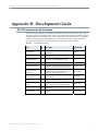
Appendix B: Development Guide 57
RS-232 Accessories Kit Contents 57
Adapters 58
Antennas 59
Appendix C: Additional Information 60
1-Year Warranty 60
Ordering Information 60
Contact MaxStream 61
©2006MaxStream,Inc.Confidential&Proprietary iii

XStream‐PKG‐R™RS‐232/485RFModem–ProductManualv5.x00[2006.02.24]
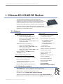
1. XStreamRS‐232/485RFModem
The XStream-PKG-R RF Modem provides long range data
communications and advanced networking for OEMs and system
integrators. Out-of-box, the modem is equipped to sustain long range
wireless links between devices. Simply enter serial data into one
modem and the data surfaces on the other end of the wireless link.
The modem transfers a standard asynchronous serial data stream
between two or more modems. Its built-in RS-232/485/422 interfacing facilitates rapid
integration into existing data systems.
1.1. Features
Long Range
9XStream-PKG-R (900 MHz) Range:
©2006MaxStream,Inc.Confidential&Proprietary 4
• Indoor/Urban: up to 1500’ (450 m)
• Outdoor line-of-sight: up to 7 miles (11 km)
w/ 2.1 dBm dipole antenna
• Outdoor line-of-sight: up to 20 miles (32 km)
w/ high gain antenna
24XStream-PKG-R (2.4 GHz) Range:
• Indoor/Urban: up to 600’ (180 m)
• Outdoor line-of-sight: up to 3 miles (5 km)
w/ 2.1 dBm dipole antenna
• Outdoor line-of-sight: up to 10 miles (16 km)
w/ high gain antenna
Receiver Sensitivity: -110 dBm (900 MHz),
-105 dBm (2.4 GHz)
Advanced Networking & Security
True peer-to-peer (no “master” required),
point-to-point, point-to-multipoint, multidrop
Retries and Acknowledgements
7 hopping channels, each with over 65,000
available network addresses
FHSS (Frequency Hopping Spread Spectrum)
1.1.1. Worldwide Acceptance
FCC Certified (USA) - Refer to Appendix A for FCC Requirements.
Systems that contain XStream RF Modems automatically inherit MaxStream Certifications.
ISM (Industrial, Scientific & Medical) frequency band
Manufactured under ISO 9001:2000 registered standards
9XStream (900 MHz) RF Modems are approved for use in US, Canada, Australia &
Israel (and more). 24XStream (2.4 GHz) Modems add Europe (EU) and other approvals.
Easy-to-Use
Out-of-Box RF Communications -
no configuration required
External DIP Switch for configuring:
• RS-232/485/422 support
(multidrop included)
• 2-wire (half-duplex) or 4-wire
RS-485/422 operation
• Parity options
7-18 VDC power supply
Simple AT and Binary commands for
programming the modem
Software-selectable serial
interfacing rates
MODBUS, CTS, RTS, DTR, DCD
(& more) I/O Support
XII™ Interference Blocking
Power-saving Sleep Modes
(as low as 6 mA)
Free & Unlimited
World-Class Technical Support

XStream‐PKG‐R™RS‐232/485RFModem–ProductManualv5.x00[2006.02.24]
©2006MaxStream,Inc.Confidential&Proprietary 5
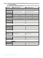
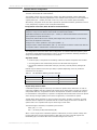
1.2. Specifications
Table1.1. XStream‐PKG‐RRS‐232/485RFModemSpecifications
Specification 9XStream-PKG-R (900 MHz) 24XStream-PKG-R (2.4 GHz)
Performance
Indoor/Urban Range Up to 1500’ (450 m) Up to 600’ (180 m)
Outdoor LOS Range
Up to 7 miles (11 km) w/ dipole antenna
Up to 20 miles (32 km) w/ high-gain antenna
Up to 3 miles (5 km) w/ dipole antenna
Up to 10 miles (16 km) w/ high-gain antenna
Transmit Power Output 100 mW (20 dBm) 50 mW (17 dBm)
Interface Data Rate 125 – 65,000 bps (software selectable) 125 – 65,000 bps (software selectable)
Throughput Data Rate 9,600 bps 19,200 bps 9,600 bps 19,200 bps
RF Data Rate 10,000 bps 20,000 bps 10,000 bps 20,000 bps
Receiver Sensitivity -110 dBm -107 dBm -105 dBm -102 dBm
Power Requirements
Supply Voltage 7-18 VDC 7-18 VDC
Receive Current 70 mA 90 mA
Transmit Current 170 mA 180 mA
Pin Sleep Power-Down 6 mA 6 mA
General
Frequency 902-928 MHz 2.4000-2.4835 GHz
Spread Spectrum Frequency Hopping, Wide band FM modulator Frequency Hopping, Wide band FM modulator
Network Topology Peer-to-Peer, Point-to-Multipoint, Point-to-Point, Multidrop Peer-to-Peer, Point-to-multipoint, Point-to-Point, Multidrop
Channel Capacity 7 hop sequences share 25 frequencies 7 hop sequences share 25 frequencies
Data Connection DB-9 DB-9
Physical Properties
Enclosure 7.1 oz. (200g), Extruded aluminum, black anodized 7.1 oz. (200g), Extruded aluminum, black anodized
Enclosure Size
2.750” x 5.500” x 1.125”
(6.99cm x 13.97” x 2.86cm)
2.750” x 5.500” x 1.125”
(6.99cm x 13.97” x 2.86cm)
Operating Temperature 0 to 70º C (commercial), -40 to 85º C (industrial) 0 to 70º C (commercial), -40 to 85º C (industrial)
Antenna
Type ½ wave dipole whip, 6.75” (17.1 cm), 2.1 dBi Gain ½ wave dipole whip, 5.25” (13.3 cm), 2.1 dBi Gain
Connector Reverse-polarity SMA Reverse-polarity SMA
Impedance 50 ohms unbalanced 50 ohms unbalanced
Certifications (Refer to www.maxstream.net for additional certifications)
FCC Part 15.247 OUR9XSTREAM OUR-24XSTREAM
Industry Canada (IC) 4214A-9XSTREAM 4214A 12008
Europe N/A ETSI, CE

XStream‐PKG‐R™RS‐232/485RFModem–ProductManualv5.x00[2006.02.24]
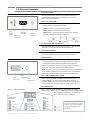
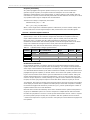
1.3. External Interface
1.1a. Power Switch
Figure1.1. FrontView
Move the Power Switch to the on (up) position to power the
Interface Board. DIP Switch [1.2a] settings are only read
during a power-up sequence.
1.1d.Power
Connector
1.1c.DB‐9
SerialPort
1.1b.I/O&
PowerLEDs
1.1a.
Power
Switch
1.1b. I/O & Power LEDs
The LED indicators visualize diagnostic status information. The
modem’s status is represented as follows:
Yellow (top LED) = Serial Data Out (to host)
Green (middle) = Serial Data In (from host)
Red (bottom) = Power/TX Indicator (Red light is on when
powered, off briefly during RF transmission)
1.1c. Serial Port (DB-9 Connector)
Standard female DB-9 (RS-232) DCE connector – This connector
can be also used for RS-485 and RS-422 connections.
1.1d. Power Connector
7-18 VDC Power Connector (Center positive, 5.5/2.1mm) – Power
can also be supplied through Pin 9 of the DB-9 Serial Port.
1.2a. DIP Switch
Figure1.2. BackView
The DIP Switch automatically configures the XStream RF Modem
to operate in different modes. Each time the modem is powered-
on, intelligence inside the XIB-R interface board (inside the
modem) programs the modem according to the positions of the
DIP Switch. [See figure below for DIP Switch settings]
1.2b.
ConfigSwitch
1.2c.
AntennaPort
1.2a.
DIPSwitch
NOTE: In cases where AT Commands should not be sent each time
the RF Modem is powered-on, the processor must be disabled by
populating J7 on the interface board inside the modem [p21].
1.2b. Config (Configuration) Switch
The Configuration Switch provides an alternate way to enter “AT
Command Mode”. To enter “AT Command Mode” at the RF
modem’s default baud rate, hold the Configuration Switch down
while powering on the modem using the Power Switch [1.1a].
1.2c. Antenna Port
©2006MaxStream,Inc.Confidential&Proprietary 6
Figure1.3. DIPSwitchSettings
Port is a 50Ω RF signal connector for connecting to an external
antenna. The connector type is RPSMA (Reverse Polarity SMA) female.
The connector has threads on the outside of a
barrel and a male center conductor.
Refertotableinthe“Automatic
DIPSwitchConfigurations”[p19]
sectionformoreinformationabout
configurationstriggeredbythe
DIPSwitch.

XStream‐PKG‐R™RS‐232/485RFModem–ProductManualv5.x00[2006.02.24]
2. InterfacingProtocol
The XStream-PKG-R RF Modem supports the following interfacing protocols:
• RS-232
• RS-485 (2-wire) Half-Duplex
• RS-485 (4-wire) and RS-422
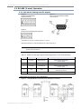
2.1. RS-232 Operation
2.1.1. DIP Switch Settings and Pin Signals
Figure2.1.Figure2.2.
RS‐232DIPSwitchSettingsPinsusedonthefemaleRS‐232(DB‐9)
SerialConnector
DIPSwitchsettingsarereadandapplied
onlywhilepowering‐on.
Table2.1. RS‐232SignalsandtheirimplementationsontheXStreamRFModem
(Low‐assertedsignalsaredistinguishedbyhorizontallineoverpinname.)
DB-9 Pin
RS-232
Name
AT Command
Reference*
Description Implementation
1 DCD DO3 Data-Carrier-Detect Connected to DSR (pin6)
2 RXD DO Received Data Serial data exiting the RF Modem (to host)
3 TXD DI Transmitted Data Serial data entering into the RF modem (from host)
4 DTR DI3 Data-Terminal-Ready Can enable POWER-DOWN on the RF Modem
5 GND - Ground Signal Ground
6 DSR DO3 Data-Set-Ready Connected to DCD (pin1)
7
/
CMD
DI2 Request-to-Send
Provides flow control or
enables “Command Mode” on the RF Modem
8 DO2 Clear-to-Send Provides flow control
9 RI - Ring Indicator
Optional power input that is connected internally to
the positive lead of the front power connector
*InsidetheXStreamRFModemisanXStreamOEMRFModule.Thenamesinthiscolumnrefertothepin
signalsoftheembeddedRFmodule.XStreamCommands[p
24]usedtoconfigurepinbehaviorsarenamed
accordingtothepinsofthemodule,nottheRS‐232connectionpins.
©2006MaxStream,Inc.Confidential&Proprietary 7

XStream‐PKG‐R™RS‐232/485RFModem–ProductManualv5.x00[2006.02.24]
Wiring Diagram: RS-232 DTE Device to a DCE RF Modem
Figure2.3.RS‐232DTE(maleconnector)devicewiredtoanXStreamRFModem(femaleconnector)
Wiring Diagram: DCE RF Modem to an RS-232 DCE Device
Figure2.4.XStreamRFModem(femaleconnector)wiredtoanRS‐232DTE(maleconnector)device
Sample Wireless Connection: DTE ÅÆ DCE DCE ÅÆ DCE
Figure2.5.TypicalwirelesslinkbetweenDTEandDCEdevices
©2006MaxStream,Inc.Confidential&Proprietary 8

XStream‐PKG‐R™RS‐232/485RFModem–ProductManualv5.x00[2006.02.24]
2.2. RS-485 (2-wire) Operation
2.2.1. DIP Switch Settings and Pin Signals
Figure2.6.Figure2.7.
RS‐485(2‐wire)Half‐DuplexPinsusedonthefemaleRS‐232(DB‐9)
DIPSwitchSettingsSerialConnector
Figure2.8.
RS‐485(2‐wire)withTermination(optional)
Termination is the 120 Ω resistor between T+ and T-.
DIP Switch settings are read and applied only while powering-on.
Note: Refer to Figures 2.15 & 2.16 for RJ-45 connector pin designations used in
RS-485/422 environments.
Table2.2. RS‐485(2‐wirehalf‐duplex)SignalsandtheirimplementationsontheXStreamRFModem
DB-9 Pin RS-485 Name Description Implementation
2 T/R- (TRA) Negative Data Line
Transmit serial data to and from the
XStream RF Modem
5 GND Ground Signal Ground
8 T/R+ (TRB) Positive Data Line
Transmit serial data to and from the
XStream RF Modem
9 PWR Power
Optional power input that is connected internally
to the front power connector
1, 3, 4, 6, 7 not used
Wiring Diagram: RS-485 (2-wire) Half-Duplex
Figure2.9.XStreamRFModeminanRS‐485(2‐wire)half‐duplexenvironment
©2006MaxStream,Inc.Confidential&Proprietary 9

XStream‐PKG‐R™RS‐232/485RFModem–ProductManualv5.x00[2006.02.24]
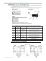
2.3. RS-485 (4-wire) & RS-422 Operation
2.3.1. DIP Switch Settings and Pin Signals
Figure2.10.Figure2.11.
RS‐485(4‐wire)andRS‐422PinsusedonthefemaleRS‐232(DB‐9)
DIPSwitchSettingsSerialConnector
Figure2.12.
RS‐485(4‐wire)&RS‐422withTermination(optional)
Termination is the 120 Ω resistor between T+ and T-.
DIP Switch settings are read and applied only while powering-on.
Table2.3. RS‐485/422(4‐wire)Signalsandtheirimplementationswith theXStream‐PKG‐RRFModem
DB-9 Pin
RS-485/422
Name
Description Implementation
2 T- (TA)
Transmit Negative
Data Line
Serial data sent from the XStream RF Modem
3 R- (RA)
Receive Negative
Data Line
Serial data received by the XStream RF Modem
5 GND Signal Ground Ground
7 R+ (RB)
Receive Positive
Data Line
Serial data received by the XStream RF Modem
8 T+ (TB)
Transmit Positive
Data Line
Serial data sent from the XStream RF Modem
9 PWR Power
Optional power input that is connected internally
to the front power connector
1, 4, 6 not used
Wiring Diagram: RS-485 (4-wire) Half-Duplex
Figure2.13.XStreamRFModeminanRS‐485(4‐wire)environment
©2006MaxStream,Inc.Confide ntial&Proprietary 10

XStream‐PKG‐R™RS‐232/485RFModem–ProductManualv5.x00[2006.02.24]
Wiring Diagram: RS-422
Figure2.14.XStreamRFModeminanRS‐485(4‐wire)environment
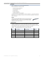
RS-485/422 Connection Guidelines
The RS-485/422 protocol provides a solution for wired communications that can tolerate high
noise and push signals over long cable lengths. RS-485/422 signals can communicate as far as
4000 feet (1200 m). RS-232 signals are suitable for cable distances up to 100 feet (30.5 m).
RS-485 offers multi-drop capability in which up to 32 nodes can be connected. The RS-422
protocol is used for point-to-point communications.
Suggestions for integrating the XStream Modem with the RS-485/422 protocol:
1. When using Ethernet twisted pair cabling: Select wires so that T+ and T- are connected to
each wire in a twisted pair. Likewise, select wires so that R+ and R- are connected to a
twisted pair. (For example, tie the green and white/green wires to T+ and T-.)
2. For straight-through Ethernet cable (not cross-over cable) – The following wiring pattern
works well: Pin3 to T+, Pin4 to R+, Pin5 to R-, Pin6 to T-
3. Note that the connecting cable only requires 4 wires (even though there are 8 wires).
4. When using phone cabling (RJ-11) – Pin2 in the cable maps to Pin3 on opposite end of cable
and Pin1 maps to Pin4 respectively.
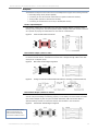
Figure2.15.Male(yellow)DB‐9toRJ‐45Adapters
Figure2.16.Female(green)DB‐9toRJ‐45Adapters
An RS-232 Accessories Kit is available that includes connectors that facilitate RS-232/485/422
and other serial communications. Refer to the Development Guide in Appendix B for information
concerning the connectors and tools included in the kit.
©2006MaxStream,Inc.Confidential&Proprietary 11

XStream‐PKG‐R™RS‐232/485RFModem–ProductManualv5.x00[2006.02.24]
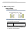
3. RFModemOperation
3.1. Serial Communications
3.1.1. RS-232 and RS-485/422 Data Flow
Devices that have a UART interface can connect directly through the pins of the XStream Modem
as is shown in the figure below.
Figure3.1. SystemDataFlowDiagraminaUART‐interfacedenvironment
(Low‐assertedsignalsdistinguishedwithhorizontallineoversignalname.)
3.1.2. Host and RF Modem I/O Settings
Serial communications between a host and an XStream RF Modem are dependent upon having
matching baud rate, parity, stop bit & number of data bits settings. Failure to enter the modem
into AT Command Mode is most commonly due to baud rate mismatch. Refer to the table below
to ensure host serial port settings match those of the modem.
Table3.1. ParametervaluescriticaltoserialcommunicationsbetweentheRFModemandhost
Parameter Setting XStream RF Modem Default Parameter Value
Baud (Serial Data Rate) 9600 bps or 19200 baud (Factory-set RF data rates)
Number of Data Bits 8 (NB parameter = 0)
Parity None (NB parameter = 0)
Number of Stop Bits 1 (NB parameter = 0)
Both the XStream RF Modem and host (PC) settings can be viewed and adjusted using
MaxStream’s proprietary X-CTU Software. Use the “PC Settings” tab to configure host settings.
Use the “Terminal” or “Modem Configuration” tabs to configure the RF Modem settings. Refer to
the RF Modem Configuration sections for more information [p
21].
©2006MaxStream,Inc.Confidential&Proprietary 12

XStream‐PKG‐R™RS‐232/485RFModem–ProductManualv5.x00[2006.02.24]
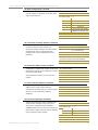
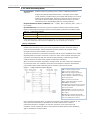
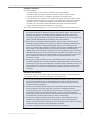
3.1.3. Flow Control
Figure3.2. InternalDataFlowDiagram
(Thefivemostcommonly‐usedpinsignalsareshown.)
DI (Data In) Buffer and Flow Control
When serial data enters the XStream Modem through the DI Pin, then the data is stored in the DI
Buffer until it can be transmitted.
When the RO parameter threshold is satisfied (refer to Transmit Mode [p
14] and Command
Descriptions [p
25] sections for more information), the modem attempts to initialize an RF
connection. If the modem is already receiving RF data, the serial data is stored in the modem’s
DI Buffer. If the DI buffer becomes full, hardware or software flow control must be implemented
in order to prevent overflow (loss of data between the host and XStream RF Modem).
How to eliminate the need for flow control:
1. Send messages that are smaller than the DI buffer size. The size of the DI buffer varies
according to the packet size and parity setting used.
2. Interface at a lower baud rate (BD Command) than the fixed RF data rate.
Two cases in which the DI Buffer may become full and possibly overflow:
1. If the serial interface data rate is set higher than the RF data rate of the modem, the modem
will receive data from the host faster than it can transmit the data over-the-air.
2. If the modem is receiving a continuous stream of RF data or if the modem is monitoring data
on a network, any serial data that arrives on the DI pin is placed in the DI Buffer. The data in
the DI buffer will be transmitted over-the-air when the modem no longer detects RF data in
the network.
Hardware Flow Control ( ). When the DI buffer is 17 bytes away from being full; by
default, the modem de-asserts (high)
to signal to the host device to stop sending data [refer
to the FT (Flow Control Threshold) and CS (DO2 Configuration) commands].
is re-asserted
after the DI Buffer has 34 bytes of memory available.
Software Flow Control (XON). XON/XOFF software flow control can be enabled using the FL
(Software Flow Control) Command. This option only works with ASCII data.
DO (Data Out) Buffer and Flow Control
When RF data is received, the data enters the DO buffer and is then sent out the serial port to a
host device. Once the DO Buffer reaches capacity, any additional incoming RF data is lost.
Two cases in which the DO Buffer may become full and possibly overflow:
1. If the RF data rate is set higher than the interface data rate of the modem, the modem will
receive data from the transmitting modem faster than it can send the data to the host.
2. If the host does not allow the modem to transmit data out from the DO buffer because of
being held off by hardware or software flow control.
Hardware Flow Control ( ). If is enabled for flow control (RT Parameter = 2), data will
not be sent out the DO Buffer as long as
is de-asserted.
Software Flow Control (XOFF). XON/XOFF software flow control can be enabled using the FL
(Software Flow Control) Command. This option only works with ASCII data.
©2006MaxStream,Inc.Confidential&Proprietary 13

XStream‐PKG‐R™RS‐232/485RFModem–ProductManualv5.x00[2006.02.24]
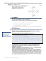
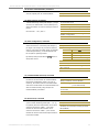
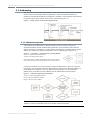
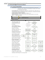
3.2. Modes of Operation
XStream RF Modems operate in five modes.
©2006MaxStream,Inc.Confidential&Proprietary 14
Figure3.3. XStreamModesofOperation
Modemcanonlybeinonemodeatatime.
3.2.1. Idle Mode
When not receiving or transmitting data, the modem is in Idle Mode. The modem uses the same
amount of power in Idle Mode as it does in Receive Mode.
The modem shifts into the other modes of operation under the following conditions:
• Serial data is received in the DI Buffer (Transmit Mode)
• Valid RF data is received through the antenna (Receive Mode)
• Command Mode Sequence is issued (Command Mode)
• Sleep Mode condition is met (Sleep Mode)
After responding to any of the preceding conditions, the modem automatically transitions back
into Idle Mode.
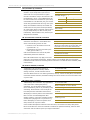
3.2.2. Transmit Mode
When the first byte of serial data is received from the UART in the DI buffer, the modem
attempts to shift to Transmit Mode and initiate an RF connection with other modems. After
transmission is complete, the modem returns to Idle Mode.
RF transmission begins after either of the following criteria is met:
1. RB bytes have been received in the DI buffer and are pending for RF transmission [refer to
RB (Packetization Threshold) command, p34].
The RB parameter may be set to any value between 1 and the RF packet size (PK), inclusive.
When RB = 0, the packetization threshold is ignored.
2. At least one character has been received in the DI buffer (pending for RF transmission) and
RO time has been observed on the UART [refer to RO (Packetization Timeout) command].
The timeout can be disabled by setting RO to zero. In this case, transmission will begin after
RB bytes have been received in the DI buffer.
After either RB or RO conditions are met, the modem then initializes a communications channel.
[Channel initialization is the process of sending an RF initializer that synchronizes receiving
modems with the transmitting modem. During channel initialization, incoming serial data
accumulates in the DI buffer.]
Serial data in the DI buffer is grouped into RF packets [refer to PK (RF Packet Size)]; converted
to RF data; then transmitted over-the-air until the DI buffer is empty.
RF data, which includes the payload data, follows the RF initializer. The payload includes up to
the maximum packet size (PK Command) bytes. As the transmitting modem nears the end of the
transmission, it inspects the DI buffer to see if more data exists to be transmitted. This could be
the case if more than PK bytes were originally pending in the DI buffer or if more bytes arrived
from the UART after the transmission began. If more data is pending, the transmitting modem
assembles a subsequent packet for transmission.
Note: RF reception must
complete before the
modem is able to enter
into Transmit Mode.

XStream‐PKG‐R™RS‐232/485RFModem–ProductManualv5.x00[2006.02.24]
©2006MaxStream,Inc.Confidential&Proprietary 15
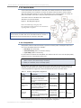
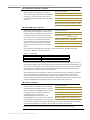
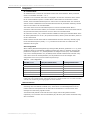
RF Data Packet
Figure3.4. DataTransmissionSequenceÆ
The RF packet is the sequence of data used for communicating information between MaxStream
* When streaming multiple RF packets, the RF Initializer is only sent in front of the first packet.
RF Initializer
is sent each time a new connection sequence begins. The RF initializer contains
n the
Header
er contains network addressing information that filters incoming RF data. The receiving
CRC (Cyclic Redundancy Check)
uilt-in error checking, a 16-bit CRC (Cyclic Redundancy
e
Modems. An RF Packet consists of an RF Initializer and RF Data.
Figure3.5. RFDataPacketComponents
An RF initializer
channel information that notifies receiving modems of information such as the hopping pattern
used by the transmitting modem. The first transmission always sends an RF initializer.
An RF initializer can be of various lengths depending on the amount of time determined to be
required to prepare a receiving modem. For example, a wake-up initializer is a type of RF
initializer used to wake remote modems from Sleep Mode (Refer to the FH, LH, HT and SM
Commands for more information). The length of the wake-up initializer should be longer tha
length of time remote modems are in cyclic sleep.
The head
modem checks for a matching Hopping Channel (HP parameter), Vendor Identification Number
(ID parameter) and Destination Address (DT parameter). Data that does not pass through all
three network filter layers is discarded.
To verify data integrity and provide b
Check) is computed for the transmitted data and attached to the end of each RF packet. On th
receiving end, the receiving modem computes the CRC on all incoming RF data. Received data
that has an invalid CRC is discarded [Refer to the Receive Mode section, next page].

XStream‐PKG‐R™RS‐232/485RFModem–ProductManualv5.x00[2006.02.24]
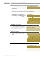
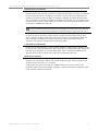
3.2.3. Receive Mode
If the modem detects RF data while in Idle Mode, the modem transitions into Receive Mode to
receive RF packets. Once a packet is received, the modem checks the CRC to ensure that the
data was transmitted without error. If the CRC data bits on the incoming packet are invalid, the
packet is discarded. If the CRC is valid, the packet proceeds to the DO Buffer.
The modem returns to Idle Mode when valid RF data is no longer detected or after an error is
detected in the received RF data.
©2006MaxStream,Inc.Confidential&Proprietary 16
Figure3.6. DataReceptionSequence
RefertotheAddressingsection[p
41]ofthe
RFCommunicationModeschapterformoreinformation
regardingaddressrecognition.
3.2.4. Sleep Modes
Sleep Modes enable the XStream Modem to operate at minimal power consumption when not in
use. Three Sleep Mode options are available:
Note: If serial data exists in the DI buffer while the modem is in
Receive Mode, the UART data will be transmitted after the modem is
finished receiving the RF data and has returned to Idle Mode.
• Pin Sleep (Host Controlled)
• Serial Port Sleep (Wake on Serial Port activity)
• Cyclic Sleep (Wake on RF activity)
For the modem to transition into Sleep Mode, the modem must have a non-zero SM (Sleep Mode)
parameter and one of the following must occur:
1. The modem is idle (no data transmission or reception) for a user-defined period of time
[Refer to the ST (Time before Sleep) command].
2. SLEEP pin is asserted (only for Pin Sleep option).
In Sleep Mode, the modem will not transmit or receive data until the modem first transitions to
Idle Mode. All Sleep Modes are enabled and disabled using SM Command. Transitions into and
out of Sleep Modes are triggered by various mechanisms as shown in the table below.
Table3.2. SummaryofSleepModeConfigurations
Sleep Mode
Setting
Transition into
Sleep Mode
Transition out of
Sleep Mode
Related
Commands
Typical Power
Consumption
Pin Sleep
(SM = 1)
A microcontroller can shut down and wake
modems by asserting (high) SLEEP pin.
Note: The modem will complete a
transmission or reception before activating
Pin Sleep.
De-assert SLEEP pin. SM 6 mA
Serial Port Sleep
(SM = 2)
Automatic transition to Sleep Mode occurs
after a user-defined period of inactivity (no
transmitting or receiving of data). The
period of activity is defined using the ST
(Time before Sleep) Command.
When serial byte is
received on the DI pin.
SM, ST 25 mA
Cyclic Sleep
(SM = 3-8)
Automatic transition to Sleep Mode occurs
in cycles as defined by the SM (Sleep
Mode) Command.
Note: The cyclic sleep time interval must be
shorter than the “Wake-up Initializer Timer”
(set by LH Command).
After the cyclic sleep
time interval elapses.
Note: Modem can be
forced into Idle Mode
if PW (Pin Wake-up)
Command is issued.
SM, ST, HT, LH,
PW
6 mA
when sleeping
FormoreinformationaboutSleepModes,refertotheindividualcommandslistedin“RelatedCommands”
columnofthetable.TheSMcommandiscentraltoallSleepModeconfigurations.

XStream‐PKG‐R™RS‐232/485RFModem–ProductManualv5.x00[2006.02.24]
Pin Sleep (SM = 1)
Pin Sleep requires the least amount of power. In order to achieve this state, the DI3 (SLEEP) pin
must be asserted (high). The modem remains in Pin Sleep until the DI3 pin is de-asserted.
After enabling Pin Sleep, the SLEEP pin controls whether the XStream Modem is active or in Sleep
Mode. When DI3 is de-asserted (low), the modem is fully operational. When DI3 is asserted
(high), the modem transitions to Sleep Mode and remains in its lowest power-consuming state
until the DI3 (SLEEP) pin is de-asserted. DI3 is only active if the modem is setup to operate in
this mode; otherwise the pin is ignored.
Once in Pin Sleep Mode, DO2 (
) is de-asserted (high), indicating that data should not be sent
to the modem. The PWR pin is also de-asserted (low) when the modem is in Pin Sleep Mode.
Note: The modem will complete a transmission or reception before activating Pin Sleep.
Serial Port Sleep (SM = 2)
Serial Port Sleep is a Sleep Mode in which the XStream Modem runs in a low power state until
serial data is detected on the DI pin.
When Serial Port Sleep is enabled, the modem goes into Sleep Mode after a user-defined period
of inactivity (no transmitting or receiving of data). This period of time is determined by ST (Time
before Sleep) Command. Once a character is received through the DI pin, the modem returns to
Idle Mode and is fully operational.
Cyclic Sleep (SM = 3-8)
Cyclic Sleep is the Sleep Mode in which the XStream Modem enters into a low-power state and
awakens periodically to determine if any transmissions are being sent.
When Cyclic Sleep settings are enabled, the XStream Modem goes into Sleep Mode after a user-
defined period of inactivity (no transmission or reception on the RF channel). The user-defined
period is determined by ST (Time before Sleep) Command.
While the modem is in Cyclic Sleep Mode, DO2 (
) is de-asserted (high) to indicate that data
should not be sent to the modem during this time. When the modem awakens to listen for data,
DO2 is asserted and any data received on the DI Pin is transmitted. The PWR pin is also de-
asserted (low) when the modem is in Cyclic Sleep Mode.
The modem remains in Sleep Mode for a user-defined period of time ranging from 0.5 seconds to
16 seconds (SM Parameters 3 through 8). After this interval of time, the modem returns to Idle
Mode and listens for a valid data packet for 100 ms. If the modem does not detect valid data (on
any frequency), the modem returns to Sleep Mode. If valid data is detected, the modem
transitions into Receive Mode and receives incoming RF packets. The modem then returns to
Sleep Mode after a Period of inactivity that is determined by ST “Time before Sleep” Command.
The modem can also be configured to wake from cyclic sleep when SLEEP/DI3 is de-asserted
(low). To configure a modem to operate in this manner, PW (Pin Wake-up) Command must be
issued. Once DI3 is de-asserted, the modem is forced into Idle Mode and can begin transmitting
or receiving data. It remains active until no data is detected for the period of time specified by
the ST Command, at which point it resumes its low-power cyclic state.
Note: The cyclic interval time defined by SM (Sleep Mode) Command must be shorter than the interval
time defined by LH (Wake-up Initializer Timer).
For example: If SM=4 (Cyclic 1.0 second sleep), the LH Parameter should equal 0x0B (“1.1” seconds).
With these parameters set, there is no risk of the receiving modem being asleep for the duration of
wake-up initializer transmission. “Cyclic Scanning” explains in further detail the relationship between
“Cyclic Sleep” and “Wake-up Initializer Timer”
©2006MaxStream,Inc.Confidential&Proprietary 17

XStream‐PKG‐R™RS‐232/485RFModem–ProductManualv5.x00[2006.02.24]
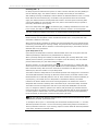
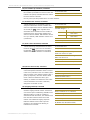
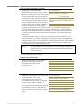
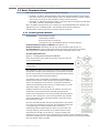
Cyclic Scanning. Each RF transmission consists of an RF Initializer and payload. The wake-up
initializer contains initialization information and all receiving modems must wake during the
wake-up initializer portion of data transmission in order to be synchronized with the transmitting
modem and receive the data.
Figure3.7. CorrectConfiguration(LH>SM)
Lengthofthewake‐upinitializerexceedsthetimeintervalofCyclicSleep.Thereceiverisguaranteedtodetect
thewake‐upinitializerandreceivetheaccompanyingpayloaddata.
Figure3.8. IncorrectConfiguration(LH<SM)
Lengthofwake‐upinitializerisshorterthanthetimeintervalofCyclicSleep.Thisconfigurationisvulnerable
tothereceiverwakingandmissingthewake‐upinitializer(andthereforealsotheaccompanyingpayloaddata).
©2006MaxStream,Inc.Confidential&Proprietary 18

XStream‐PKG‐R™RS‐232/485RFModem–ProductManualv5.x00[2006.02.24]
3.2.5. Command Mode
To modify or read modem parameters, the modem must first enter into Command Mode, the
state in which incoming characters are interpreted as commands. Two command types are
available for programming the modem:
• AT Commands
• Binary Commands
For modified parameter values to persist in the modem registry, changes must be saved to non-
volatile memory using WR (Write) Command. Otherwise, parameters are restored to previously
saved values when the modem is powered off and then on again.
AT Commands
To Enter AT Command Mode:
1. Send the 3-character command sequence “+++” and observe guard times before and after
the command characters. [Refer to the “Default AT Command Mode Sequence” below.] The
“Terminal” tab (or other serial communications software) of the X-CTU Software can be used
to enter the sequence.
[OR]
2. Assert (low) the pin and turn the power going to the modem off and back on. This
result can be achieved by keeping the configuration switch pressed while turning off, then on
again the power supplying the RF Modem)
Default AT Command Mode Sequence (for transition to Command Mode):
• No characters sent for one second [refer to the BT (Guard Time Before) Command]
• Input three plus characters (“+++”) within one second [refer to the CC (Command
Sequence Character) Command.]
• No characters sent for one second [refer to the AT (Guard Time After) Command.]
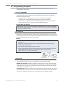
To Send AT Commands:
Send AT commands and parameters using the syntax shown below:
Figure3.9. SyntaxforsendingATCommands
NOTE: To read a parameter value stored in a register, leave the parameter field blank.
The preceding example would change the modem Destination Address to “1F”. To store the new
value to non-volatile (long term) memory, the Write (ATWR) Command must follow.
System Response. When a command is sent to the modem, the modem will parse and execute
the command. Upon successful execution of a command, the modem returns an “OK” message. If
execution of a command results in an error, the modem returns an “ERROR” message.
To Exit AT Command Mode:
1. Send ATCN (Exit Command Mode) Command.
[OR]
2. If no valid AT Commands are received within the time specified by CT (Command Mode
Timeout) Command, the Modem automatically returns to Idle Mode.
For examples that illustrate the steps of programming the modem using AT Commands, refer to
the RF Modem Configuration [p
21] chapter.
©2006MaxStream,Inc.Confidential&Proprietary 19

XStream‐PKG‐R™RS‐232/485RFModem–ProductManualv5.x00[2006.02.24]
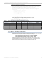
Binary Commands
Sending and receiving parameter values using binary commands is the fastest way to change
operating parameters of the XStream RF Modem. Binary commands are used most often to
sample signal strength (RS parameter) and/or error counts; or change modem addresses and
channels for polling data systems. Since the sending and receiving of register values takes place
through the same serial data path as 'live' data (received RF payload), interference between the
two types of data can be a concern.
Common questions about using binary commands:
• What are the implications of asserting CMD while live data is being sent or received?
• After sending serial data, is there a minimum time delay before CMD can be asserted?
• Is a delay required after CMD is de-asserted before payload data can be sent?
• How does one discern between live data and data received in response to a command?
The CMD pin must be asserted in order to send binary commands to the RF modem. The CMD pin
can be asserted to recognize binary commands anytime during the transmission or reception of
data. The status of the CMD signal is only checked at the end of the stop bit as the byte is shifted
into the serial port. The application does not allow control over when data is received, except by
waiting for dead time between bursts of communication.
If the command is sent in the middle of a stream of payload data to be transmitted, the
command will essentially be executed in the order it is received. If the radio is continuously
receiving data, the radio will wait for a break in the received data before executing the command.
The
signal will frame the response coming from the binary command request [Figure 3.10].
A minimum time delay of 100 µs (after the stop bit of the command byte has been sent) must be
observed before the CMD pin can be de-asserted. The command executes after all parameters
associated with the command have been sent. If all parameters are not received within 0.5
seconds, the modem returns to Idle Mode.
Note: When parameters are sent, they are two bytes long with the least significant byte sent first.
Binary commands that return one parameter byte must be written with two parameter bytes.
Refer to p23 for a binary programming example.
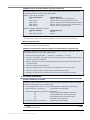
Commands can be queried for their current value by sending the command logically ORed (bit-
wise) with the value 0x80 (hexadecimal) with CMD asserted. When the binary value is sent (with
no parameters), the current value of the command parameter is sent back through the DO pin.
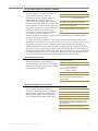
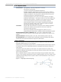
Figure3.10. BinaryCommandWritethenRead
Signal#4isCMD
Signal#1istheDINsignaltotheradio
Signal#2istheDOUTsignalfromtheradio
Signal#3is
In this graph, a value was written to a register and
then read out to verify it. While not in the middle
of other received data, note that the
(DO2
pin) signal outlines the data response out of the
modem.
IMPORTANT: For the XStream Modem to recognize a binary command, the RT (DI2
Configuration) parameter must be set to one. If binary programming is not
enabled (RT ≠ 1), the modem will not recognize that the CMD pin is asserted and
therefore will not recognize the data as binary commands.
©2006MaxStream,Inc.Confidential&Proprietary 20
Page is loading ...
Page is loading ...
Page is loading ...
Page is loading ...
Page is loading ...
Page is loading ...
Page is loading ...
Page is loading ...
Page is loading ...
Page is loading ...
Page is loading ...
Page is loading ...
Page is loading ...
Page is loading ...
Page is loading ...
Page is loading ...
Page is loading ...
Page is loading ...
Page is loading ...
Page is loading ...
Page is loading ...
Page is loading ...
Page is loading ...
Page is loading ...
Page is loading ...
Page is loading ...
Page is loading ...
Page is loading ...
Page is loading ...
Page is loading ...
Page is loading ...
Page is loading ...
Page is loading ...
Page is loading ...
Page is loading ...
Page is loading ...
Page is loading ...
Page is loading ...
Page is loading ...
Page is loading ...
Page is loading ...
-
 1
1
-
 2
2
-
 3
3
-
 4
4
-
 5
5
-
 6
6
-
 7
7
-
 8
8
-
 9
9
-
 10
10
-
 11
11
-
 12
12
-
 13
13
-
 14
14
-
 15
15
-
 16
16
-
 17
17
-
 18
18
-
 19
19
-
 20
20
-
 21
21
-
 22
22
-
 23
23
-
 24
24
-
 25
25
-
 26
26
-
 27
27
-
 28
28
-
 29
29
-
 30
30
-
 31
31
-
 32
32
-
 33
33
-
 34
34
-
 35
35
-
 36
36
-
 37
37
-
 38
38
-
 39
39
-
 40
40
-
 41
41
-
 42
42
-
 43
43
-
 44
44
-
 45
45
-
 46
46
-
 47
47
-
 48
48
-
 49
49
-
 50
50
-
 51
51
-
 52
52
-
 53
53
-
 54
54
-
 55
55
-
 56
56
-
 57
57
-
 58
58
-
 59
59
-
 60
60
-
 61
61


Ask a question and I''ll find the answer in the document
Finding information in a document is now easier with AI
Related papers
Other documents
-
 Cables Direct SL-925 Datasheet
-
 CallingSYS ZZQ8 User manual
-
Climax Technology RP-29 User manual
-
Black Box MDR210A-485 User manual
-
 Data Connect DSP19.2 User manual
-
B&B Electronics 9XTend-PKG-E User manual
-
Warwick X7220 User manual
-
Sunricher SR-3001DIN User manual
-
DAVIS 7625 Owner's manual
-
 Xpress XEB09-C User manual


