Page is loading ...

OWNER’S REFERENCE
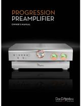
EVOLUTION ONE
MONAURAL POWER AMPLIFIER
EVOLUTION

Evolution One Monaural Power Amplifier Owner’s Reference, v05.0
Kr
ell Industries, Inc.
45 Connair Road
Orange, CT 06477-3650 USA
TEL 203-799-9954
FAX 203-891-2028
E-MAIL krell@krellonline.com
WEBSITE http://www.krellonline.com
This product complies with the EMC directive (89/336/EEC) and the low-voltage directive
(73/23/EEC).
WARNINGS
The amplifier must be placed on a firm, level surface where it is not exposed to dripping or splash-
ing.
The ventilation grids on the top of the amplifier and the space underneath the amplifier must be
unobstr
ucted at all times during operation. Do not place flammable
material above or beneath the
amplifier.
Before making connections to the amplifier, ensure that the back panel power switch is down.
Make sur
e all cable ter
minations ar
e of the highest quality
, free from frayed ends, short circuits,
or cold solder joints.
The differential circuitry employed with an Evolution One Monaural Power Amplifier requires special
attention when connecting speakers. Do not connect the negative speaker terminals together. Do
not connect the negative speaker terminals to ground.
Do not connect an Evolution One Monaural Power Amplifier to a loudspeaker selector device that
employs a common gr
ound scheme, as it may short-circuit the amplifier output.
THERE ARE NO USER SERVICEABLE PARTS INSIDE AN EVOLUTION ONE MONAURAL POWER
AMPLIFIER.
Please contact Krell if you have questions not addressed in this guide.
This pr
oduct is manufactur
ed in the United States of America. Kr
ell
®
is a r
egister
ed trademark of Kr
ell Industries, Inc., and is r
estricted for use
by Krell Industries, Inc., its subsidiaries, and authorized agents. Evolution Bias
™ is a trademark of Krell Industries, Inc. and is a Krell technology
based on U.S. Patent No. 5,331,291. CAST
™, Evolution CAST™, and Kr
ell Current Mode
™ ar
e trademarks of Krell Industries, Inc. All other
trademarks ar
e r
egister
ed to their r
espective companies.
© 2005 by Krell Industries, Inc. All rights reserved P/N 307772

1
iii
Contents
List of Illustrations, page iv
A Letter from Dan D’Agostino, page 1
SECTION ONE: About Krell, page 3
The Krell Legacy, Revolutionary Krell CAST Technology,
Ensuring Maximum Per
formance, and Definition of Terms
SECTION TWO: Unpacking and Placement, page 12
Opening the Evolution One Shipping Cartons
SECTION THREE: Anatomy of an Amplifier, page 15
Features and Benefits of the Evolution One Design
SECTION FOUR: Connecting an Evolution One Amplifier to Your System, page 19
CAST and Voltage Connections, Connection Steps,
DC Protection Circuitry, and Remote Control Options
SECTION FIVE: Amplifier Operation, page 22
Powering Up, Adjusting Power Meter Modes,
Switching between CAST and Voltage Connections,
Amplifier Care
SECTION SIX: Amplifier Troubleshooting, page 26
WARRANTY, page 28
RETURN AUTHORIZATION PROCEDURE, page 30
SPECIFICATIONS, page 31

iv
List of Illustrations
Figure 1, page 15
Evolution One Amplifier and
Power Supply Chassis Front Panels
Inset Evolution One Amplifier Channel: Front Panel View
Figure 2, page 16
Evolution One Amplifier and
Power Supply Chassis Back Panels
Figure 3, page 17
Evolution One Amplifier Chassis Top
Figure 4, page 18
Evolution One Power Supply Chassis Top

continue
d
A Letter from Dan D’Agostino
Dear Audio Enthusiast,
Thank you for your purchase of the Evolution One.
The Evolution One Monaural Power Amplifier represents a watershed in my design
philosophy and in my quest for amplifiers that deliver absolute truth in music
reproduction. This new amplifier operates solely in the current domain, with only
one voltage gain stage at its output. I have always been fascinated by the artistry
inherent in great musical performances, and I believe that no component in an
audio system equates more closely to the full range of musical expression than
the power amplifier. The Evolution One reproduces real-life dynamics and trans-
parency in a manner that I have not experienced prior to this design. It is my
pleasure to make it available to you.
Krell amplifiers are best known for their ability to drive any loudspeaker to sound
its best, without regard to impedance or efficiency. The Evolution One amplifier
joins this awesome current capability with a new, ultra-linear circuit topology. It is a
strong belief of mine that linearity, an amplifier’s ability to output an exact dupli-
cate of the input signal, is the ultimate measure of that amplifiers worth. I drive
Krell amplifier designs toward the common goal of linearity; through the rigorous
application of Krell design principles that focus our efforts on four major perform-
ance factors: distortion, bandwidth, output impedance and current capability. The
Evolution One excels in each of these areas, delivering absolute accuracy from
extr
emely low levels of output, vir
tually at pr
eamplifier levels, to astounding, awe-
inspiring amounts of power.
As the foundation of my new Evolution Series, the Evolution One Monaural Power
Amplifier is designed to complement the Evolution T
wo Monaural Power
Pr
eamplifier per
fectly. Combine the Evolution One and Two with my new LAT-1000
loudspeakers, and experience the extraordinary capabilities of the Evolution
System.
1

I have some exciting news for you. Work on a new source component for the
Evolution Series is ongoing as of this writing. Possessed of the unique Evolution
technologies that power the amplifier and preamplifier, this Evolution source will
expose the real advantages of the latest recording formats while taking compact
disc playback to the next level. I encourage you to audition it as soon as it is
released.
Sincer
ely,
Daniel D’Agostino
Chief Executive Officer
2
(A Letter from Dan D’Agostino continued)

continue
d
SECTION ONE
About Krell
This section describes the Krell Legacy, innovative Krell amplifier design and technol-
ogy, and defines key terms used in this reference.
The Krell Legacy
“I design every Krell component to set the standard
for workmanship, style, and performance.”
Dan D’Agostino
High-end audio is a demanding pursuit—an ongoing quest for excellence in
music reproduction that drives equipment manufacturers to strive for the absolute
in design and performance. With a keen understanding of this passionate drive,
Krell Industries, Inc., was founded in 1980.
Over the past 2-1/2 decades, Krell has earned a distinguished reputation for engi-
neering innovation and product excellence. The company’s history is replete with
product introductions that have deeply impacted the high-end audio industry.
The most discriminating audiophiles and product reviewers have consistently
recognized Krell components for standard-setting performance.
The Evolution One amplifier brings Krell design to a new level, setting a standard for
performance that will not soon be matched. The shear breadth of this amplifier’s
dynamic range capabilities conveys a startling realism that transcends previous
designs. Seemingly unlimited frequency response, combined with unerring accu-
racy and fortitude, extend a tradition that began with the first Krell amplifier — the
KSA-100.
The KSA–100 was the first high-power, high-current, true Class A biased stereo
power amplifier available to audiophiles. It was the first Krell product, and its
resounding success established Krell as an important new technological contrib-
utor to high-end audio.
3

From the KSA–100 to the present, Krell C.E.O. Dan D’Agostino has continually
“pushed the envelope” of performance in his search for greater amplifier power.
His exploration of new technologies, driven by his never-ending quest to elevate
the standard of excellence, has resulted in breakthrough audio designs. Over the
years, the Krell line of power amplifiers, including benchmark products such as the
KRS–100, KRS–200, and the Audio Standard models, has established a legacy of
unparalleled sonic performance.
The Krell product line has diversified, but Dan’s fundamental research into amplifier
design and performance remains at the core of the company’s achievements. Every
Krell component upholds the legacy, incorporating unique technologies that are the
direct result of Dan’s discoveries in audio amplification.
The Evolution One amplifiers build on the Krell legacy. They provide unprecedent-
ed linearity with the control and accuracy that only comes from superior current
capability. The sound is lively and unconstrained, in a manner that evokes live per-
formance and the true sound of instruments.
Dan D’Agostino remains committed to the development of new designs and
technologies. And the Krell legacy will continue to evolve with products that deliver
innovative engineering, perfection in build quality, and outstanding audio performance.
4
(SECTION ONE: About Krell continued)

continue
d
5
Revolutionary Krell CAST Technology
Current Audio Signal Transmission, termed CAST, is a revolutionary method of con-
necting analog audio components for unparalleled sonic performance. Innovative
engineering combines the new Krell CAST circuitry with existing Krell Current Mode
technology to create entire CAST systems that reproduce music with incredible range,
tonality, and precision.
The Voltage Signal Transmission
and the Traditional Audio System
Traditionally, signal is transmitted in the voltage domain between two components.
In an audio system, each component is a discrete entity with unique characteristics
that act upon the musical signal independently. Each component is unaware of the
other components in the system. The cables that connect the components also
have their own electrical characteristics, which affect the sonic presentation of the
entire system. CAST transmission unifies individual components and interconnects
into an electrically linked whole. The original signal remains unaltered from source to
speaker.
CAST Basics
Here’s how a CAST audio system works. Internally, each CAST source transfers,
or amplifies, current using Krell Current Mode circuitry. This current signal is
then output using CAST circuitry. When the signal is received by a CAST input,
Kr
ell Cur
r
ent Mode cir
cuitr
y again takes over until the signal reaches the loud-
speaker
. By maintaining the musical signal in the cur
r
ent domain from beginning
to end, an entire CAST system behaves as if it is one component. With CAST,
cir
cuit boar
d pr
oper
ties and signal transmission aber
rations between compo
-
nents ar
e eliminated. Cable impedances and their ef
fects on the transmitted sig
-
nal are non-existent.
How CAST and Krell Current Mode Interact
While CAST is a new method of transferring the musical signal between compo-
nents, its origin stems from Krell Current Mode, the technology developed to
transfer the musical signal within a component. CAST combined with Krell Current
Mode takes circuitry signal transmission to the next evolutionary level. In essence,
Krell Current Mode maintains the integrity of the signal within the component and

6
(How CAST and Kr
ell Current Mode Interact continued)
CAST preserves the transmitted signal between components. Together, CAST and
Krell Current Mode technologies unify separate Krell components into a
single
global circuit.
Krell Current Mode technology enjoys bandwidth increases up to an
order of magnitude greater than their voltage based counterparts. This dramatic
increase in circuit bandwidth delivers near perfection in the audible band that typi-
cally suffers from phase distortions in voltage circuits.
CAST Cable Construction
A CAST system uses cables manufactured by Krell and other manufacturers spe-
cially licensed by Krell. Thin and flexible CAST cables are constructed with the
same build quality as other Krell components and are aesthetically matched to the
components that Krell manufactures. An all-metal body and locking connectors
with gold contacts are part of the standard no-compromise specification devel-
oped for every CAST cable made.
Evolution CAST
By employing radical current mirror circuitry, the Evolution components elevate the
CAST technology to another level. This advanced use of the technology increases
the linearity, transient speed, and bandwidth of the Evolution components while
reducing the distortion by an order of magnitude.
The Best Musical Performance
When you operate a CAST system, you will hear significant improvements in every
performance area: speed, precision, dynamic range, depth and width of the sound
stage, transient impact, tonal balance, har
monic distor
tion, and mor
e. The goal for
CAST is the same company goal used for all Krell products. Krell strives for the
delivery of the best performance of a musical event for you, using the full expres-
sion of technology to date.
(SECTION ONE: About Krell continued)

7
Ensuring Maximum Performance
“My pursuit of excellence in sound reproduction and
my love of great musical performance has led me
to the Evolution One Amplifier, and fuels the ongoing
Evolution design effort at Krell.”
Dan D’Agostino
The Krell Evolution One Monaural Power Amplifier, built upon the foundation of
huge, regulated power supplies and output stages, is designed to drive any
loudspeaker with complete control. The product of breakthrough Krell technolo-
gy, this amplifier provides a sound that is supremely dynamic and musical.
Indeed, it is the sound of the music itself.
Core Technologies
Class A, Balanced, Current Mode Gain
Topologies from Input to Output
Audio signal voltages are converted to currents at the amplifier input, and the
audio signal remains in the current domain throughout the entire amplifier until
the output stages. All signal gain is realized in the current domain using propri-
etary multiple-output current mirrors with extraordinary open loop linearity. The
current mirrors in the final gain stages use 36 pairs of high voltage, high speed
transistors. Originally developed for demanding, high bandwidth video circuits,
these transistors help yield gain stages with superb accuracy and very low dis-
tor
tion. The signal path is fully complementar
y and fully balanced from input to
output. The driver and output stages use 28 pairs of 150 Volt, 14 Amp, 50
megaher
tz power transistors mounted on Kr
ell-designed high ef
ficiency heat
sinks.
All transistors operate in Class A mode. Independent complementary pre-
driver and driver stages for the positive and negative output transistors make
the output stages extr
emely fast and linear
. The output stage develops 450
Watts into an 8 Ohm load, 900 Watts into 4 Ohms, and 1800 Watts into 2
Ohms. This unique cir
cuit is imper
vious to low-impedance or r
eactive loads;
the Evolution One amplifier simply drives any loudspeaker with absolute confi
-
dence, achieving the very best possible sonic results.
continue
d

8
Impedance Advantage
The output impedance of the final gain stages is one hundredth that of the final gain
stage in most power amplifiers. This provides extremely wide bandwidth and very
high current capability. The amplifier does not employ global negative feedback—the
final gain stages use only 8 dB of local, nested negative feedback. This is one five-
hundredth the amount used in most solid-state power amplifiers. The result is an
extraordinarily open, liquid, effortless sound.
Robust Power Supply Regulation
For Absolute Voltage Stability
The rails powering the amplifier’s low level and gain stages are regulated twice
for total immunity from fluctuations in the AC mains and virtually noise-free out-
put. All the regulators use current-mode circuitry for wide bandwidth, low output
impedance, and complete immunity to varying load conditions. The high-current
regulators powering the amplifier output stages use fully complementary gain
stages and output drivers. The resulting wide bandwidth and low output imped-
ance of the Evolution One surpasses even the stringent demands of the amplifier
output stages.
The driver and output stages in the high current regulators use 14 pairs of the
same robust, high performance power transistors used in the amplifier output
stages. All the regulators are located in the amplifier chassis to provide ultra low
impedance supply rails for the audio circuitry.
Evolution Bias Control Systems
The new Evolution Bias system features 12 individual bias levels for optimum
performance and efficiency. Evolution Bias constantly compares the audio signal
at the input stage with impedance at the output stage, and adjusts the bias cur-
rent accordingly. In addition, a proprietary bias monitor continuously measures
and adjusts the output stage bias, eliminating the need for futur
e adjustment or
calibration.
(SECTION ONE: About Krell continued)

continue
d
9
Separate Power Supplies Are Quiet and Powerful
Housed in a separate chassis, the power supply makes use of extensive electri-
cal and magnetic shielding to keep radiated interference out of critical amplifier
circuits. Internal high current line conditioning circuitry filters RF noise on the
AC mains, as well as compensating for asymmetric power waveforms and DC
on the mains. A dedicated 165 VA toroidal transformer with six independent
secondary windings powers the amplifier’s low level stages, gain stages, and
control circuitry. Power for the high current regulators and amplifier output stages
comes from two massive 2500 VA toroidal transformers. These in turn drive eight
35-amp bridge rectifiers and 120,000 microfarads of filter capacitance. High relia-
bility connectors with 56 machined, gold plated, 20-amp contacts transmit these
tremendous power reserves to the regulators.
Advanced Microprocessor Control Monitors
Critical Operational Parameters
If the DC level at the amplifier inputs exceeds a safe level, the microprocessor
control automatically switches in DC blocking capacitors to prevent damage to
the input stages or the loudspeakers. The microprocessor control measures the
load impedance in real time to optimize the performance of the amplifier and
power supply or, in the case of a short circuit, to shut the amplifier off. It monitors
the regulator output voltages, the symmetry between the two halves of the bal-
anced output stages, and it monitors the operating temperatures of the three
main heat sinks. If any of the heat sinks become too hot, the microprocessor
control adjusts the operating parameters of the amplifier and power supply to
help the circuitry run cooler. If the temperature of any of the heat sinks becomes
unsafe, the microprocessor control shuts the amplifier off until it cools down.
In the event of a major protection fault the microprocessor flashes a diagnostic
code on the power/stand-by LED (4). The RMS output voltage and current sig-
nals used by the micr
opr
ocessor are also used by the power meter (6) (7), on the
amplifier front panel, to display accurate power measurements.
For more infor-
mation on diagnostic codes, see
Amplifier Troubleshooting, on page 26.

Definition of Terms
Following are the definitions of key terms used in your owner’s reference manual.
Inputs and Outputs
Balanced
A symmetrical input or output circuit that has equal impedance from both input ter-
minals to a common ground reference point. The industry standard for professional
and sound recording installations, balanced connections have 6 dB more gain than
single-ended connections and allow the use of long interconnect cables. Balanced
connections are completely immune to induced noise from the system or the envi-
ronment.
CAST and Evolution CAST
Krell Current Audio Signal Transmission, or CAST, is a proprietary Krell circuit tech-
nology for connecting analog components, transmitting the audio waveform between
components in the current domain rather than in the voltage domain. The speed and
bandwidth provided by Krell CAST and its circuitry update, Evolution CAST, yield
accurate, realistic music reproduction, enabling connected components to perform
as if they are all part of a single circuit.
Operation
Off
When the power br
eaker switch on the back panel of the power supply is in the
down position, and the power/stand-by LEDs (4), the backlight (5), and the power
meter scale (6) are not illuminated, the amplifier is off.
Stand-by
A low power consumption status that keeps the audio and regulator circuits at idle.
The power/stand-by LEDs (4) are illuminated in red, when the amplifier is in the
stand-by mode. Kr
ell r
ecommends leaving the amplifier in the stand-by mode when
it is not playing music.
(
SECTION ONE: About Krell continued)
10

(Operation continued)
Operational Mode
When the power/stand-by LEDs (4), the backlight (5), and the power meter scale (6)
are illuminated in blue, the amplifier is in the operational mode and ready to play
music.
Technology
Krell Current Mode
A proprietary Krell circuit topology in which the audio gain stages of a component
operate in the current rather than voltage domain. This unique technology provides
the component with exceptional speed, and a wide bandwidth.
Evolution Bias
A patented microprocessor control system that maintains Class A bias operation
regardless of musical demand. Class A bias is the most accurate method used to
amplify musical signals. Evolution Bias maximizes an amplifier’s efficiency both in
power consumption and heat generation.
11

12
Unpacking and Placement
This section describes the procedures for safely unpacking and placing your
Evolution One Monaural Power Amplifier. Each Evolution One amplifier channel
is shipped in 2 cartons: a power supply chassis in 1 carton and an amplifier
chassis in the other carton.
Opening the Amplifier Shipping Carton
Each Evolution One shipping carton measures 27.5 in. (69.9 cm) wide by 12 in.
(30.5 cm) high by 20.8 in. (52.8 cm) deep and contains 1 amplifier power supply
chassis or 1 amplifier chassis.
Power Supply Chassis. The combined weight of the shipping carton and the
power supply chassis is 110 lbs. (49.8 kg). Each power supply chassis measures
15.8 in. (40 cm) wide by 6.4 in. (16.1 cm) high by 20.5 in. (52.2 cm) deep and
weighs 95 lbs. (43 kg).
Amplifier Chassis. The combined weight of the shipping carton and the
amplifier chassis is 70 lbs. (31.7 kg). Each amplifier chassis measures 15.8 in.
(40 cm) wide by 6.2 in. (15.8 cm) high by 21.5 in. (54.7 cm) deep and weighs
55 lbs. (24.9 kg).
To Remove the Chassis from the Shipping Carton
1. Open a shipping carton and remove the top layer of foam. You see these
items:
1 Evolution One power supply chassis or amplifier chassis
1 packet containing the owner’s reference and warranty card
2. Orient the shipping box so that one person stands at the front of the carton
and the other person stands at the back of the car
ton.
2 people needed
SECTION TWO

13
3. Simultaneously grasp the pair of cardboard handle cutouts at the front and
back of the carton and lift the chassis straight up out of the carton.
2 people needed
4. Place the chassis in a safe location and remove the protective plastic
wrapping.
2 people needed
5. Open the remaining 3 cartons of the Evolution One, using steps 1-4 above
as a guide.
2 people needed
6. Place the power supply chassis where you intend to use the assembled ampli-
fier channel. Krell recommends that you do not move the amplifier after it is
assembled.
2 people needed
7. Locate the 4 locating pins (23) and the power connector (24) in the top plate of
the power supply chassis.
See Figure 4, on page 18.
8. Make certain the amplifier chassis feet (13) and the amplifier power connector
(not shown) align with the 4 power supply locating pins and power supply
power connector as you lower the amplifier chassis onto the power supply
chassis. Use the outer edges of the amplifier and power supply chassis as a
guide. The dimensions of the chassis are identical. When viewed from the top,
the power supply chassis will disappear beneath the amplifier chassis, indicat-
ing proper alignment of the feet, pins, and power connectors.
2 people needed
9. Visually inspect the union between the amplifier and power supply chassis.
Verify that the each of the amplifier chassis feet has descended upon the
power supply chassis locating pins, and that both halves of the power connec-
tors have mated squarely with one another.
10. Pr
ess firmly on the amplifier chassis to ensure that the connector is properly
engaged.
continue
d

14
Placement
Before you install an Evolution One amplifier into your system, please follow the
guidelines in this section to choose its proper location. This will facilitate a clean,
trouble-free installation.
Each Evolution One amplifier requires at least two inches (5 cm) of clearance
on each side and at least eight inches (20 cm) of clearance above the compo-
nent to provide adequate ventilation. An Evolution One amplifier channel meas-
ures 15.8 in. (40 cm) wide by 12.5 in. (31.6 cm) high by 21.5 in.(54.7 cm) deep
and weighs 150 lbs. (67.9 kg).
Although Evolution Bias circuitry reduces the high heat dissipation and heat out-
put of traditional Class A circuitry, Evolution One amplifiers still can become hot
under normal operation. When the front and rear of a cabinet are open, the air
space between the chassis and shelf must be unobstructed. If you place the
amplifier in a closed cabinet, you may need to modify shelf spacing or use small
fans to increase ventilation
.
Place the amplifier as close to the loudspeakers as possible. Although Krell CAST
technology permits you to use interconnect cables of any length, try to keep the
cable length to a minimum. All Evolution One amplifiers drive the lowest imped-
ances with ease. When impedance is added due to long loudspeakers cable
lengths, amplifier power is wasted in the cable. Long loudspeakers cables reduce
the maximum power that is delivered in the loudspeakers.
AC Power Guidelines
Each Evolution One amplifier channel needs to be operated from a dedicated AC
circuit rated at a minimum of 20 amps. A 30 amp AC circuit is preferable, but not
required.
Use the power cord shipped with the amplifier channel to make the AC connection.
Operation with a power cor
d other than the one supplied by Krell may induce
noise, limit current, or otherwise impair the amplifier’s ability to perform optimally.
(SECTION TWO: Unpacking and Placement continued)

15
SECTION THREE
Anatomy of an Amplifier
This section describes Evolution One features and benefits.
Figure 1 Evolution One Amplifier and Power Supply Chassis Front Panels
1 Amplifier Chassis
2 Power Supply Chassis
3 Power/Stand-by Button
4 Power/Stand-by LED
5 Backlight
6 Power Meter Scale
7
Power Meter Wand
8
CAST LED
9
50 W Scale LED
10 5000 W Scale LED
11 Cast/Balanced Button
12 Meter Range Button
13
Amplifier Feet
14
Power Supply Feet
POWER
CAST
5000W
50W
Inset
Evolution One
Amplifier Channel
Fr
ont Panel V
iew
1
6
7
8
4
3
2
4
910 11
12
1
3
14
5
continue
d

Figure 2 Evolution One Amplifier and Power Supply Chassis Back Panels
16
15 Balanced Input
16
CAST Input
17
Amplifier Binding Posts
18 RC-5 Input
19 12 V Trigger In/Out
20 IEC Power Cord
Receptacle
21 Power Breaker Switch
IN
IN
OUT
MADE IN USA
NO USER SERVICEABLE PARTS INSIDE
KRELL INDUSTRIES, INC.
45 CONNAIR ROAD
ORANGE, CT 06477-3650
USA
EVOLUTION ONE
EVOLUTION ONE
BALANCED
INPUT
CAST
INPUT
MADE IN USA
NO USER SERVICEABLE PARTS INSIDE
KRELL INDUSTRIES, INC.
45 CONNAIR ROAD
ORANGE, CT 06477-3650
USA
EVOLUTION ONEEVOLUTION ONE
50/60 Hz
19
20
21
16
15
17
18
1
2
(
SECTION THREE: Anatomy of an Amplifier continued)
/