
OWNER'S MANUAL
(FOR MODELS MANUFACTURED SINCE 1/14)
MODEL W1764
1/8 HP POWER FEEDER
Phone: (360) 734-3482 • Online Technical Support: [email protected]
COPYRIGHT © JUNE, 2007 BY WOODSTOCK INTERNATIONAL, INC. REVISED FEBRUARY, 2014 (BL)
WARNING: NO PORTION OF THIS MANUAL MAY BE REPRODUCED IN ANY SHAPE OR FORM WITHOUT
THE WRITTEN APPROVAL OF WOODSTOCK INTERNATIONAL, INC.
#9695CR Printed in Taiwan

This manual provides critical safety instructions on the proper setup,
operation, maintenance, and service of this machine/tool. Save this
document, refer to it often, and use it to instruct other operators.
Failure to read, understand and follow the instructions in this manual
may result in fire or serious personal injury—including amputation,
electrocution, or death.
The owner of this machine/tool is solely responsible for its safe use.
This responsibility includes but is not limited to proper installation in
a safe environment, personnel training and usage authorization,
proper inspection and maintenance, manual availability and compre-
hension, application of safety devices, cutting/sanding/grinding tool
integrity, and the usage of personal protective equipment.
The manufacturer will not be held liable for injury or property
damage from negligence, improper training, machine modifications or
misuse.
Some dust created by power sanding, sawing, grinding, drilling, and
other construction activities contains chemicals known to the State of
California to cause cancer, birth defects or other reproductive harm.
Some examples of these chemicals are:
• Lead from lead-based paints.
• Crystalline silica from bricks, cement and other masonry products.
• Arsenic and chromium from chemically-treated lumber.
Your risk from these exposures varies, depending on how often you
do this type of work. To reduce your exposure to these chemicals:
Work in a well ventilated area, and work with approved safety equip-
ment, such as those dust masks that are specially designed to filter
out microscopic particles.

SET UPELECTRICAL MAINTENANCE
SERVICE PARTS
OPERATIONS
SAFETYINTRODUCTION
USE THE QUICK GUIDE PAGE LABELS TO SEARCH OUT INFORMATION FAST!
Contents
INTRODUCTION .....................................2
Woodstock Technical Support .................. 2
SAFETY ...............................................6
Standard Machinery Safety Instructions ...... 6
Additional Safety for Power Feeders .......... 8
ELECTRICAL .........................................9
Circuit Requirements ............................ 9
Grounding Requirements ...................... 10
Extension Cords ................................ 10
SETUP .............................................. 11
Unpacking ....................................... 11
Inventory ........................................ 11
Cleaning Machine ............................... 12
Assembly ......................................... 13
Base Mounting .................................. 16
Test Run .......................................... 18
OPERATIONS....................................... 19
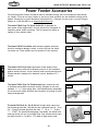
General .......................................... 19
Power Feeder Accessories .................... 20
MAINTENANCE .................................... 21
General .......................................... 21
Cleaning ......................................... 21
Lubrication ...................................... 21
SERVICE ............................................ 22
General .......................................... 22
Wheel Replacement............................ 22
Brush Replacement ............................ 22
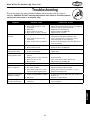
Troubleshooting ................................. 23
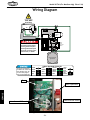
Wiring Diagram ................................. 24
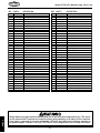
PARTS .............................................. 25
WARRANTY ........................................ 29

-2-
INTRODUCTION
Model W1764 (For Machines Mfg. Since 1/14)
Woodstock Technical Support
Woodstock International, Inc. is committed to customer satisfaction. Our intent with this manual is to
include the basic information for safety, setup, operation, maintenance, and service of this product.
In the event that questions arise about your machine, please contact Woodstock International Technical
Support at (360) 734-3482 or send e-mail to: tech-support@shopfox.biz. Our knowledgeable staff will
help you troubleshoot problems or process warranty claims.
INTRODUCTION
If you need the latest edition of this manual, you can download it from http://www.shopfox.biz.
If you have comments about this manual, please contact us at:
Woodstock International, Inc.
Attn: Technical Documentation Manager
P.O. Box 2309
Bellingham, WA 98227
Email: manuals@woodstockint.com

-3-
INTRODUCTION
Model W1764 (For Machines Mfg. Since 1/14)
MACH INE
SPECIFICATIONS
Phone #: (360) 734–3482 • Online Tech Support: tech–support@shopfox.biz • Web: www.shopfox.biz
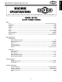
MACHINE
SPECIFICATIONS
Motor
Type ................................................................................................. Universal Variable Speed
Horsepower .............................................................................................................. 1/8 HP
Voltage ...................................................................................................................... 120V
Prewired .....................................................................................................................120V
Phase ....................................................................................................................... Single
Amps ......................................................................................................................... 1.2A
Speed ............................................................................................................ 550—3300 RPM
Cycle ........................................................................................................................ 60 Hz
Number of Speeds .................................................................................................... Variable
Power Transfer ...................................................................................................... Gear Box
Bearings ................................................................................................... Lubricated for Life
Main Specifications
Operation Info
Minimum Workpiece Length ....................................................................................... 5 in.
Number of Feed Speeds ....................................................................................... Variable
Feed Speeds ................................................................................................. 6.5—39 FPM
Swing ............................................................................................................ 360 deg.
Vertical Movement ........................................................................................... 10-1/4 in.
Horizontal Movement ........................................................................................ 10-1/4 in.
Rotation .............................................................................................. Forward, Reverse
Roller Info
Number of Rollers ....................................................................................................... 3
Roller Width ................................................................................................... 1–3/16 in.
Roller Diameter ..................................................................................................... 3 in.
Roller Suspension Travel ...................................................................................... 5/16 in.
Maximum Height of Rollers ....................................................................................... 6 in.
Distance Between Rollers .................................................................................... 3–3/4 in.
Overall Dimensions
Weight.............................................................................................................. 20 lbs.
Length/Width/Height ................................................................................. 31 x 11 x 12 in.
Arm Diameter ................................................................................................. 15/16 in.
Construction Materials
Roller Construction ................................................................................. Synthetic Rubber
Housing Construction .................................................................................. Cast Aluminum
Supports Construction ................................................................................. Cast Aluminum
Column Construction .............................................................................................. Steel
Paint ................................................................................................................. Epoxy
MODEL W1764
1/8 HP POWER FEEDER
Model W1764 Specifications, Page 1 of 2, Last Updated 1/24/14

-4-
INTRODUCTION
Model W1764 (For Machines Mfg. Since 1/14)
Shipping Dimensions
Type .................................................................................................................. Cardboard
Content ................................................................................................................. Machine
Weight .................................................................................................................... 27 lbs.
Length/Width/Height ........................................................................................ 11 x 22 x 9 in.
Electrical
Switch ................................................................................................ On/Off Variable Speed
Switch Voltage ............................................................................................................ 120V
Cord Length ................................................................................................................ 7 ft.
Cord Gauge ..............................................................................................................18 AWG
Recommended Breaker Size .............................................................................................. 15A
Included Plug ................................................................................................................. Ye s
Other
ISO Factory ............................................................................................................ ISO 9001
Country of Origin ...................................................................................................... Taiwan
Warranty ................................................................................................................ 2 Years
Assembly Time .....................................................................................................20 Minutes
Optional Accessories
Quick Holder ...................................................................................................... Model D3868
Extra Roller ....................................................................................................... Model D3870
Features
Spring Tensioned Rollers
Heavy–Duty Gear Reduction Gearbox with Hardened Gears
Universal Positioning with Handle Locks
Model W1764 Specifications, Page 2 of 2, Last Updated 6/7/12

-5-
INTRODUCTION
Model W1764 (For Machines Mfg. Since 1/14)
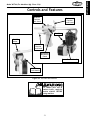
Controls and Features
Power Feeder Handle
Ball Joint
Lock Handle
Dust Port
Horizontal
Movement
Crank
Vertical
Position
Lock Lever
Horizontal
Position
Lock Lever
Rotation
Position
Lock Lever
1
⁄8 HP
Motor
Figure 22. Controls and features.
To reduce your risk of
serious injury, read this
entire manual BEFORE
using machine.

-6-
SAFETY
Model W1764 (For Machines Mfg. Since 1/14)
Indicates a potentially hazardous situation which, if not avoided,
MAY result in minor or moderate injury.
Indicates an imminently hazardous situation which, if not avoided,
WILL result in death or serious injury.
Indicates a potentially hazardous situation which, if not avoided,
COULD result in death or serious injury.
This symbol is used to alert the user to useful information about
proper operation of the equipment or a situation that may cause
damage to the machinery.
NOTICE
SAFETY
OWNER’S MANUAL.
Read and understand this
owner’s manual BEFORE using machine.
TRAINED OPERATORS ONLY.
Untrained operators
have a higher risk of being hurt or killed. Only
allow trained/supervised people to use this
machine. When machine is not being used,
disconnect power, remove switch keys, or
lock-out machine to prevent unauthorized
use—especially around children. Make
workshop kid proof!
DANGEROUS ENVIRONMENTS.
Do not use
machinery in areas that are wet, cluttered,
or have poor lighting. Operating machinery
in these areas greatly increases the risk of
accidents and injury.
MENTAL ALERTNESS REQUIRED.
Full mental
alertness is required for safe operation of
machinery. Never operate under the influence
of drugs or alcohol, when tired, or when
distracted.
ELECTRICAL EQUIPMENT INJURY RISKS. You can
be shocked, burned, or killed by touching live
electrical components or improperly grounded
machinery. To reduce this risk, only allow an
electrician or qualified service personnel to
do electrical installation or repair work, and
always disconnect power before accessing or
exposing electrical equipment.
DISCONNECT POWER FIRST. Always disconnect
machine from power supply BEFORE making
adjustments, changing tooling, or servicing
machine. This eliminates the risk of injury
from unintended startup or contact with live
electrical components.
EYE PROTECTION. Always wear ANSI-approved
safety glasses or a face shield when operating
or observing machinery to reduce the risk of
eye injury or blindness from flying particles.
Everyday eyeglasses are not approved safety
glasses.
Standard Machinery Safety Instructions
For Your Own Safety,
Read Manual Before Operating Machine
The purpose of safety symbols is to attract your attention to possible hazardous conditions. This
manual uses a series of symbols and signal words intended to convey the level of importance of the
safety messages. The progression of symbols is described below. Remember that safety messages by
themselves do not eliminate danger and are not a substitute for proper accident prevention mea-
sures—this responsibility is ultimately up to the operator!
SAFETY
Standard Machinery Safety Instructions

-7-
SAFETY
Model W1764 (For Machines Mfg. Since 1/14)
WEARING PROPER APPAREL. Do not wear
clothing, apparel, or jewelry that can become
entangled in moving parts. Always tie back
or cover long hair. Wear non-slip footwear to
avoid accidental slips, which could cause loss
of workpiece control.
HAZARDOUS
DUST. Dust created while using
machinery may cause cancer, birth defects,
or long-term respiratory damage. Be aware of
dust hazards associated with each workpiece
material, and always wear a NIOSH-approved
respirator to reduce your risk.
HEARING PROTECTION.
Always wear hearing
protection when operating or observing
loud machinery. Extended exposure to this
noise without hearing protection can cause
permanent hearing loss.
REMOVE ADJUSTING TOOLS.
Tools left on
machinery can become dangerous projectiles
upon startup. Never leave chuck keys,
wrenches, or any other tools on machine.
Always verify removal before starting!
INTENDED USAGE.
Only use machine for its
intended purpose—never make modifications
without prior approval from Woodstock
International. Modifying machine or using
it differently than intended will void the
warranty and may result in malfunction or
mechanical failure that leads to serious
personal injury or death!
AWKWARD POSITIONS.
Keep proper footing and
balance at all times when operating machine.
Do not overreach! Avoid awkward hand
positions that make workpiece control difficult
or increase the risk of accidental injury.
CHILDREN & BYSTANDERS.
Keep children and
bystanders at a safe distance from the work
area. Stop using machine if they become a
distraction.
GUARDS & COVERS.
Guards and covers reduce
accidental contact with moving parts or flying
debris—make sure they are properly installed,
undamaged, and working correctly.
FORCING MACHINERY. Do not force machine. It
will do the job safer and better at the rate for
which it was designed.
NEVER STAND ON MACHINE. Serious injury may
occur if machine is tipped or if the cutting
tool is unintentionally contacted.
STABLE MACHINE. Unexpected movement during
operation greatly increases risk of injury or
loss of control. Before starting, verify machine
is stable and mobile base (if used) is locked.
USE RECOMMENDED ACCESSORIES. Consult
this owner’s manual or the manufacturer for
recommended accessories. Using improper
accessories will increase risk of serious injury.
UNATTENDED OPERATION. To reduce the risk
of accidental injury, turn machine OFF and
ensure all moving parts completely stop
before walking away. Never leave machine
running while unattended.
MAINTAIN WITH CARE. Follow all maintenance
instructions and lubrication schedules to
keep machine in good working condition. A
machine that is improperly maintained could
malfunction, leading to serious personal injury
or death.
CHECK DAMAGED PARTS. Regularly inspect
machine for any condition that may affect
safe operation. Immediately repair or replace
damaged or mis-adjusted parts before
operating machine.
MAINTAIN POWER CORDS. When disconnecting
cord-connected machines from power, grab
and pull the plug—NOT the cord. Pulling the
cord may damage the wires inside, resulting
in a short. Do not handle cord/plug with wet
hands. Avoid cord damage by keeping it away
from heated surfaces, high traffic areas, harsh
chemicals, and wet/damp locations.
EXPERIENCING DIFFICULTIES. If at any time
you experience difficulties performing the
intended operation, stop using the machine!
Contact Technical Support at (360) 734-3482.

-8-
SAFETY
Model W1764 (For Machines Mfg. Since 1/14)
Additional Safety for Power Feeders
ATTACHED MACHINERY.
Follow all warnings and
safety information for the attached machine
doing the cutting work.
HAND SAFETY
. Keep hands away from rotating
parts on power feeder and spinning blade
or cutter of associated machine. Turn power
feeder and associated machine OFF and only
use a brush or compressed air to remove
sawdust.
INSTALLING GUARDS.
Install guards, fences, and
hold-downs before starting attached machine
or power feeder. Repair or replace guards
promptly if they become damaged.
KICKBACK.
Occurs when workpiece is ejected
from machine with great force, striking
operator or bystanders. Commonly caused by
improper machine or power feeder setup.
VERIFY EACH SETUP.
Ensure that power feeder
is set up correctly and firmly secured before
feeding workpiece. An improperly adjusted
power feeder could increase the risk of
kickback, because it will continue feeding
when stock is not properly positioned for the
cut.
FEATHERBOARD. When cutting long or large
stock that is difficult to feed properly, use
a featherboard before powerfeeder (on the
infeed side) to maintain even pressure and
control of workpiece against fence, and help
reduce risk of kickback.
FEED WORKPIECE PROPERLY. Verify blade or
cutter of associated machine is at full speed
before feeding stock with power feeder.
Do not feed workpiece too quickly. Verify
power feeder wheels are slightly lower than
workpiece. Stop power feeder before stopping
cutting tool.
WORKPIECE SUPPORT. Support workpiece
continuously during operation as required. Use
auxiliary stands or support tables for long or
wide stock.
ADJUSTMENTS/MAINTENANCE. Make sure power
feeder is turned OFF, disconnected from
power, and all moving parts are completely
stopped before doing adjustments or
maintenance.
MAIN INJURY HAZARDS: Death, amputation, or crushing injuries from getting entangled in
moving parts—which may include being pulled into the cutting tool on attached machinery;
death, blindness, broken bones, or bruises from being struck by an ejected workpiece
(kickback). To minimize your risk of these hazards, always heed the following information:
READ and understand this
entire manual before using
this machine. Serious per-
sonal injury may occur
if safety and operational
information is not under-
stood and followed. DO
NOT risk your safety by
not reading!
USE this and other machinery with cau-
tion and respect. Always consider safety
first, as it applies to your individual work-
ing conditions. No list of safety guidelines
can be complete—every shop environment
is different. Failure to follow guidelines
could result in serious personal injury,
damage to equipment or poor work results.

-9-
ELECTRICAL
Model W1764 (For Machines Mfg. Since 1/14)
ELECTRICAL
Circuit Requirements
This machine must be connected to the correct size and
type of power supply circuit, or fire or electrical damage
may occur. Read through this section to determine if an
adequate power supply circuit is available. If a correct
circuit is not available, a qualified electrician MUST install
one before you can connect the machine to power.
A power supply circuit includes all electrical equipment
between the breaker box or fuse panel in the building
and the machine. The power supply circuit used for
this machine must be sized to safely handle the full-
load current drawn from the machine for an extended
period of time. (If this machine is connected to a circuit
protected by fuses, use a time delay fuse marked D.)
Circuit Requirements for 120V
This machine can be converted to operate on a 110V
power supply (details about voltage conversion can be
found later in this manual). The 110V power supply circuit
must have a verified ground and meet the requirements
that follow:
Circuit Type ...................... 120V, 60 Hz, Single-Phase
Circuit Size ............................................. 15 Amps
Plug/Receptacle .................................... NEMA 5-15
Full-Load Current Rating
The full-load current rating is the amperage a machine
draws at 100% of the rated output power. On machines
with multiple motors, this is the amperage drawn by the
largest motor or sum of all motors and electrical devices
that might operate at one time during normal operations.
Full-Load Current Rating at 120V ................. 1.2 Amps
The machine must be properly set up
before it is safe to operate. DO NOT
connect this machine to the power
source until instructed to do so later in
this manual.
Incorrectly wiring or grounding this
machine can cause electrocution, fire,
or machine damage. To reduce this risk,
only an electrician or qualified service
personnel should do any required
electrical work on this machine.
NOTICE
The circuit requirements listed in this
manual apply to
a dedicated circuit—
where only one machine will be running
at a time. If this machine will be
connected to a shared circuit where
multiple machines will be running at the
same time, consult with an electrician
to ensure that the circuit is properly
sized for safe operation.

-10-
ELECTRICAL
Model W1764 (For Machines Mfg. Since 1/14)
Grounding Requirements
This machine MUST be grounded. In the event of certain
types of
malfunctions or breakdowns, grounding provides
a path of least resistance for electric current
to travel—in
order
to reduce the risk of electric shock.
Improper connection of the equipment-grounding
wire
will
increase
the risk of electric shock. The wire with green
insulation
(with/without yellow stripes) is the equipment-
grounding
wire. If repair or replacement of the power
cord or plug is necessary, do not connect the equipment-
grounding
wire to a live (current carrying) terminal.
Check with a qualified electrician or service personnel
if
you do not understand these grounding requirements,
or if
you are in doubt about whether the tool is
properly grounded.
If you ever notice that a cord or
plug is damaged or worn, disconnect it from power, and
immediately replace it with a new one.
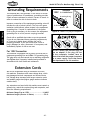
Grounding Prong
Neutral Hot
5-15 PLUG
GROUNDED
5-15 RECEPTACLE
120V
Figure 23. NEMA 5-15 plug & receptacle.
DO NOT modify the provided plug or
use an adapter if the plug will not
fit the receptacle. Instead, have an
electrician install the proper receptacle
on a power supply circuit that meets
the requirements for this machine.
Extension Cords
We do not recommend using an extension cord with
this machine. Extension cords cause voltage drop, which
may damage electrical components and shorten motor
life. Voltage drop increases with longer extension cords
and smaller gauge sizes (higher gauge numbers indicate
smaller sizes).
Any extension cord used with this machine must contain a
ground wire
, match the required
plug and receptacle, and
meet the following requirements:
Minimum Gauge Size at 120V ...................... 14 AWG
Maximum Length (Shorter is Better) ................50 ft.
For 120V Connection
This machine is equipped with a power cord that has an
equipment-grounding
wire and NE M A 5-15 grounding plug.
The plug
must only be inserted into a matching
receptacle
(
see Figure) that is properly installed and grounded in
accordance with local codes and ordinances.

-11-
SETUP
Model W1764 (For Machines Mfg. Since 1/14)
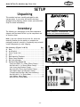
The following is a description of the main components
shipped with the Model W1764. Lay the components out
to inventory them.
Note: If you can't find an item on this list, check the
mounting location on the machine or examine the
packaging materials carefully. Occasionally we pre-install
certain components for safer shipping.
Box Inventory (Figures 24 & 25) Qty
A. Base ..........................................................1
B. Arm Bracket ................................................1
C. Power Feeder Unit ........................................1
D. Arm ..........................................................1
E. Base Mounting Template .................................1
F. Elbow Clamp Assembly ...................................1
G. Ball Joint Assembly ........................................1
H. Hardware Bag (Figure 25) ...............................1
—Cap Screw M10-1.5 x 25mm (Elbow Clamp) .........1
—Hex Bolt M10-1.5 x 50mm (Elbow Clamp) ...........3
—Lock Lever (Arm Bracket Clamp) .....................1
—Hex Nut M8-1.25mm (Arm Bracket Clamp) ..........1
—Flat Washer 8mm (Arm Bracket Clamp) ............1
—T-Handle and Pivot Bar (Ball Joint Assembly) .......1
—Hex Bolt M10-1.5 x 35mm (Base) .....................4
—Lock Washer 10mm (Base) .............................8
—Hex Nut M10-1.5mm (Base) ............................7
Inventory
Keep machine disconnected from
power until instructed otherwise.
This machine has been carefully packaged for safe
transportation. If you notice the machine has been
damaged during shipping, please contact your authorized
Shop Fox dealer immediately.
Unpacking
SETUP
Figure 24. Box inventory.
Figure 25. Hardware inventory.
C
F
A
E
B
D
G
H
H

-12-
SETUP
Model W1764 (For Machines Mfg. Since 1/14)
To prevent
corrosion during shipment and storage of your
machine, the factory has coated t
he bare metal surfaces
of your machine
with a heavy-duty rust prevention
compound
.
I
f you are unprepared or impatient, this compound can
be difficult to
remove. To ensure that the removal of this
coating is as easy as possible, please gather the correct
cleaner, lubricant, and tools listed below:
• Cleaner/degreaser
designed to remove storage wax
and grease
• Safety glasses & disposable gloves
•
Solvent brush or paint brush
• Disposable Rags
To
remove the rust preventative coating, do these
steps
:
1.
DISCONNECT THE MACHINE FROM POWER!
2.
Put on safety glasses and disposable gloves.
3
. Using a liberal amount of your cleaner/degreaser,
Coat all surfaces that have the coating, and let soak
for few minutes.
4
. Wipe off the surfaces. If your cleaner/degreaser is
effective, the coating will wipe off easily.
Tip: To clean off thick coats of the rust preventative
compound on flat surfaces, use a PLASTIC paint
scraper to scrape off the majority of the coating
before wiping it off with your rag. (Do not use a
metal scraper or you may scratch your machine.)
5
. Repeat the cleaning steps as necessary until all of
the compound is removed.
6
. To prevent rust on the freshly cleaned surfaces,
immediately coat with a quality metal protectant.
Gasoline and petroleum
products have low flash
points and can explode
or cause fire if used to
clean machinery. Avoid
using these products
to clean machinery.
Many cleaning solvents
are toxic if inhaled.
Minimize your risk
by only using these
products in a well
ventilated area.
NOTICE
In a pinch, automotive degreasers,
mineral spirits or WD•40 can be used
to remove rust preventative coating.
Before using these products, though,
test them on an inconspicuous area of
your paint to make sure they will not
damage it.
Cleaning Machine

-13-
SETUP
Model W1764 (For Machines Mfg. Since 1/14)
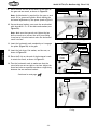
Figure 26. Assembled elbow clamp
assembly.
To assemble the power feeder, do these steps:
1. Oil the T-handle threads and position the elbow
clamp assembly onto the feeder base, as shown in
Figure 26.
2. Thread the T-handle into the feeder base until the
elbow is snug.
3. Insert the arm into the ball-joint ball and secure
both together with the M10-1.5 x 25mm cap screw
shown in Figure 27.
4. Insert the ball joint assembly into the power feed
socket shown in Figure 27.
5. Insert the ball-joint socket into the power feed
socket as shown in Figure 28, so it rests against the
ball-joint ball.
Note: Lubrication is not necessary for the ball joint
assembly.
6. Align the ball-joint socket with the power feeder
socket and insert the pivot bar, as shown in Figure
28.
7. Lightly oil the T-handle threads.
8. Thread the T-handle through the pivot bar so the
end of the T-handle bolt presses against the ball-
joint socket firmly, as shown in Figure 28.
Elbow
Clamp
Figure 28. Assembled ball joint assembly.
Figure 27. Arm, ball joint and socket
assembly.
Power Feed
Socket
Arm
Ball-Joint Ball
Ball-Joint Socket
T-Handle
Pivot Bar
T-Handle
Feeder
Base
Cap Screw
To correctly position this power feeder on your table top,
completely assemble the power feeder first, then refer
to Base Mounting on Page 16. With the power feeder
unit completely assembled, it will be easier to determine
where on the table top to drill your base mounting holes,
so you can take advantage of the full range of power
feeder swing and adjustments.
Assembly

-14-
SETUP
Model W1764 (For Machines Mfg. Since 1/14)
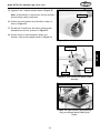
Figure 29. Arm bracket gearing.
Arm
9. Place the arm into the arm bracket so the teeth of
the gear and arm mesh, as shown in Figure 29.
Note: No lubrication is required for the gear or rack
teeth. Oil or grease will gather debris making the
horizontal adjustment of the power feeder difficult.
10. Secure the arm bracket cover onto the arm bracket
with three M10-1.5 x 35 hex bolts and washers (see
Figure 30).
Note: Make sure that you do not tighten the hex
bolts so much as to prevent the arm from sliding
in and out of the arm bracket when the horizontal
crank is turned.
11. Insert the horizontal crank completely so it engages
the spline (Figure 29) in the gear.
12. Insert the lock lever, flat washer, and hex nut, as
shown in Figure 30.
13. Place the E-clip on the end of the horizontal crank
to retain the crank, as shown in Figure 31.
14. Turn the horizontal crank to make sure that the
cover bolts are not too tight or too lose. Adjust the
three hex bolts as required to achieve a slight drag
between the arm and arm bracket.
Arm Bracket
Figure 31. Horizontal movement handle
E-clip.
E-Clip
Continued on next page
Figure 30. Assembling arm bracket.
Horizontal Crank
Arm Bracket
Cover
Lock Lever
Spline
Flat Washer
Hex Nut

-15-
SETUP
Model W1764 (For Machines Mfg. Since 1/14)
Figure 33. Arm bracket and elbow clamp
assembly.
15. Lightly oil the T-handle threads shown in Figure 32.
Note: No lubrication is required for the arm bracket
and the elbow clamp connection.
16. Position the arm bracket onto the elbow clamp, as
shown in Figure 33.
17. Thread the T-handle into the elbow clamp so both
assemblies are secure, as shown in Figure 33.
18. Use the levers to lock the power feeder into
position, such as the example shown in Figure 34.
Figure 32. Arm bracket handle threads.
Oil Threads
Figure 34. Typical power feed mounting
using an optional Model D3868 Quick
Holder.
Model D3868 Quick Holder
Arm Bracket
Elbow
Clamp
T-Handle

-16-
SETUP
Model W1764 (For Machines Mfg. Since 1/14)
Assemble the power feeder before you mount the
base to determine where on the table top to drill
your base mounting holes, so you can maximize
power feeder swing and adjustment options.
There are three mounting options available,
Through-Bolt Mounting, Direct Mounting, and
Quick Holder Mounting options discussed on Page
17. Choose an option that suits your requirements.
Your final goal is to be able to use the handcranks
and lock levers to position the power feeder
wheels so they are parallel with the table
surface, and
1
⁄8" lower than the thickness of your
workpiece.
Base Mounting
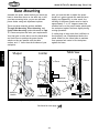
Also, you must be able to adjust the power
feeder so it points towards the machine fence
slightly (see Figure 35). In other words, the
tracking of the power feeder must be toed-in
approximately 1° to 1.5° degrees toward the
machine fence, so the power feeder wheels push
the workpiece against the fence slightly during
cutting operations.
If cutting long or large stock that is difficult to
feed properly, use a featherboard before the
power feeder (on the infeed side) to maintain
even pressure and control of the workpiece
against the fence.
Feed
Shaper
Cutter
Feed
Jointer
Cutterhead
Fence Fence
4th-Roller
Models
Feed
Table Saw
Blade
Fence
Optional
Featherboard
Figure 35. Typical power feed mounting on a shaper, jointer, and tablesaw.
Continued on next page

-17-
SETUP
Model W1764 (For Machines Mfg. Since 1/14)
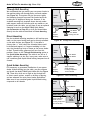
Through-Bolt Mounting
We recommend that you mount your new power feeder to
the machine table with through-bolts, nuts and washers
(see Figure 36). This option will give the most rigidity
and clamping strength to prevent the feeder base from
twisting out of alignment during use. However, if the
included mounting bolt template shows that any under-
table support webs will interfere with any washer or nut
locations under the table, you will have to use an optional
clamping kit such as the Model D3868 Quick Holder
(see Accessories on Page 20), or drill and thread holes
directly into the table as described in Direct Mounting.
Direct Mounting
Use the included mounting template to drill and tap your
table, so the power feeder base can be directly mounted
to the table surface (see Figure 37). If the table is
thinner than
3
⁄8" thick where the threaded holes would
be drilled and tapped, or if support webbing is in the
way, the threads may strip or loosen as the power feeder
is used. Thread locking compound will not cure this
problem. Revert to the Through-Bolt Mounting option or
the Quick Holder Mounting if the table is too thin or if
support webbing is in the way. In any case, make sure to
use a medium-grade liquid thread locking compound on all
threads.
Quick Holder Mounting
For temporary or permanent installation of your power
feeder without drilling into the table, you can purchase
and install the Model D3868 Quick Holder Kit (see Figure
38). These kits, while not as rigid as the through-bolt
or direct mount options, require no drilling or tapping,
and are adequate for most power feeder applications.
Make sure to use a medium-grade liquid thread locking
compound on all threads.
Figure 36. Through-bolt mounting.
Machine Table
Flat Washer
Flat Washer
Lock Washer
Locking Hex Nut
Table
Support
Webbing
Bolt
Feeder
Base
Machine Table
Lock Washer
Feeder
Base
Quick Holder
Quick
Holder
Bolt
Apply A Medium
Grade Thread
Locking Compound
To The Threads
Figure 38. Quick holder mounting.
Figure 37. Direct mounting.
Machine Table
Table
Support
Webbing
Bolt
Feeder
Base
Lock Washer
Flat Washer
Apply A Medium
Grade Thread
Locking Compound
To The Threads

-18-
SETUP
Model W1764 (For Machines Mfg. Since 1/14)
Loose hair and clothing could get
caught in machinery and cause serious
personal injury. Keep loose clothing
rolled up and long hair tied up and
away from machinery.
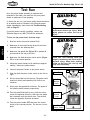
Once the power feeder assembly is complete and
mounted on the table, you must test run your power
feeder to make sure it runs properly.
If, during the test run, you cannot easily locate the source
of an unusual noise or vibration, stop using the power
feeder immediately, then review the Troubleshooting
table on Page 23.
If you still cannot remedy a problem, contact our
Technical Support at (360) 734-3482 for assistance.
To test run the power feed, do these steps:
1. Read the entire instruction manual first!
2. Make sure all tools and foreign objects have been
removed from the tabletop area.
3. Make sure the speed dial (Figure 39) is pushed IN
and turned all the way to the left.
4. Make sure the feed direction rocker switch (Figure
39) is in the central position.
5. Adjust the power feeder so all wheels are approxi-
mately 1" above the table surface.
6. Connect the power feeder to the power source.
7. Push the feed direction rocker switch to the left or
right.
8. Pull the speed dial out all the way. The power feed
should run slowly and smoothly with little or no
vibration.
9. Slowly turn the speed dial clockwise. The speed of
the wheels should increase respectively.
10. Turn the speed dial back to zero, push the rocker
switch the opposite direction, then turn the speed
dial clockwise until the wheels turn. They should
rotate the opposite direction as before.
11. Turn the power feeder OFF and move the rocker
switch to the central position. The test run is com-
plete.
Test Run
Figure 39. Feeder motor controls.
Speed Dial
Feed Direction
Rocker Switch
Feet Per
Minute
Scale
Meters Per
Minute
Scale
OFF
ON
Projectiles thrown from the machine
could cause serious eye injury. Wear
safety glasses to reduce the risk of
injury.
Page is loading ...
Page is loading ...
Page is loading ...
Page is loading ...
Page is loading ...
Page is loading ...
Page is loading ...
Page is loading ...
Page is loading ...
Page is loading ...
Page is loading ...
Page is loading ...
-
 1
1
-
 2
2
-
 3
3
-
 4
4
-
 5
5
-
 6
6
-
 7
7
-
 8
8
-
 9
9
-
 10
10
-
 11
11
-
 12
12
-
 13
13
-
 14
14
-
 15
15
-
 16
16
-
 17
17
-
 18
18
-
 19
19
-
 20
20
-
 21
21
-
 22
22
-
 23
23
-
 24
24
-
 25
25
-
 26
26
-
 27
27
-
 28
28
-
 29
29
-
 30
30
-
 31
31
-
 32
32


Ask a question and I''ll find the answer in the document
Finding information in a document is now easier with AI
Related papers
-
Woodstock D3096 Owner's manual
-
-
-
-
-
Woodstock THE SHOP FOX W1500 User manual
-
Grizzly Industrial G0826 Owner's manual
-
-
Grizzly W1805 Owner's manual
-
Other documents
-
-
Life Fitness TCWHL User manual
-
-
-
Wilton PF3-EZ User manual
-
Delta 36-851 Owner's manual
-
Powermatic PF-33 Feeder, 1HP 3PH 460V, 4 Speed User manual
-
-
-