
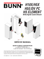
H10X/H5X
H5E/DV PC
H5 ELEMENT
With Digital Control Board
SERVICE MANUAL
BUNN-O-MATIC CORPORATION
POST OFFICE BOX 3227
SPRINGFIELD, ILLINOIS 62708-3227
PHONE: (217) 529-6601 FAX: (217) 529-6644
To ensure you have the latest revision of the manual or to obtain the illustrated parts catalog, please visit
the Bunn-O-Matic website, at www.bunn.com. This is absolutely FREE, and the quickest way to obtain
the latest catalog and manual updates. Contact Bunn-O-Matic Corporation at 1-800-286-6070 to obtain
a paper copy of the required Illustrated Parts Catalog mailed via U.S. Postal Service.
42311.0000B 05/11 © 2011 BUNN-O-MATIC CORPORATION

2
BUNN-O-MATIC COMMERCIAL PRODUCT WARRANTY
Bunn-O-Matic Corp. (“BUNN”) warrants equipment manufactured by it as follows:
1) All equipment other than as specifi ed below: 2 years parts and 1 year labor.
2) Electronic circuit and/or control boards: parts and labor for 3 years.
3) Compressors on refrigeration equipment: 5 years parts and 1 year labor.
4) Grinding burrs on coffee grinding equipment to grind coffee to meet original factory screen sieve analysis:
parts and labor for 3 years or 30,000 pounds of coffee, whichever comes fi rst.
These warranty periods run from the date of installation BUNN warrants that the equipment manufactured by
it will be commercially free of defects in material and workmanship existing at the time of manufacture and
appearing within the applicable warranty period. This warranty does not apply to any equipment, component or
part that was not manufactured by BUNN or that, in BUNN’s judgment, has been affected by misuse, neglect,
alteration, improper installation or operation, improper maintenance or repair, damage or casualty. This warranty is
conditioned on the Buyer 1) giving BUNN prompt notice of any claim to be made under this warranty by telephone
at (217) 529-6601 or by writing to Post Offi ce Box 3227, Springfi eld, Illinois 62708-3227; 2) if requested by
BUNN, shipping the defective equipment prepaid to an authorized BUNN service location; and 3) receiving prior
authorization from BUNN that the defective equipment is under warranty.
THE FOREGOING WARRANTY IS EXCLUSIVE AND IS IN LIEU OF ANY OTHER WARRANTY, WRITTEN OR
ORAL, EXPRESS OR IMPLIED, INCLUDING, BUT NOT LIMITED TO, ANY IMPLIED WARRANTY OF EITHER
MERCHANTABILITY OR FITNESS FOR A PARTICULAR PURPOSE. The agents, dealers or employees of BUNN
are not authorized to make modifi cations to this warranty or to make additional warranties that are binding on
BUNN. Accordingly, statements by such individuals, whether oral or written, do not constitute warranties and
should not be relied upon.
If BUNN determines in its sole discretion that the equipment does not conform to the warranty, BUNN, at its
exclusive option while the equipment is under warranty, shall either 1) provide at no charge replacement parts
and/or labor (during the applicable parts and labor warranty periods specifi ed above) to repair the defective
components, provided that this repair is done by a BUNN Authorized Service Representative; or 2) shall replace
the equipment or refund the purchase price for the equipment.
THE BUYER’S REMEDY AGAINST BUNN FOR THE BREACH OF ANY OBLIGATION ARISING OUT OF THE SALE OF
THIS EQUIPMENT, WHETHER DERIVED FROM WARRANTY OR OTHERWISE, SHALL BE LIMITED, AT BUNN’S
SOLE OPTION AS SPECIFIED HEREIN, TO REPAIR, REPLACEMENT OR REFUND.
In no event shall BUNN be liable for any other damage or loss, including, but not limited to, lost profi ts, lost sales,
loss of use of equipment, claims of Buyer’s customers, cost of capital, cost of down time, cost of substitute
equipment, facilities or services, or any other special, incidental or consequential damages.
392, AutoPOD, AXIOM, BrewLOGIC, BrewMETER, Brew Better Not Bitter, BrewWISE, BrewWIZARD, BUNN Espress, BUNN
Family Gourmet, BUNN Gourmet, BUNN Pour-O-Matic, BUNN, BUNN with the stylized red line, BUNNlink, Bunn-OMatic,
Bunn-O-Matic, BUNNserve, BUNNSERVE with the stylized wrench design, Cool Froth, DBC, Dr. Brew stylized Dr. design,
Dual, Easy Pour, EasyClear, EasyGard, FlavorGard, Gourmet Ice, Gourmet Juice, High Intensity, iMIX, Infusion Series,
Intellisteam, My Café, PowerLogic, Quality Beverage Equipment Worldwide, Respect Earth, Respect Earth with the styl-
ized leaf and coffee cherry design, Safety-Fresh, savemycoffee.com, Scale-Pro, Silver Series, Single, Smart Funnel, Smart
Hopper, SmartWAVE, Soft Heat, SplashGard, The Mark of Quality in Beverage Equipment Worldwide, ThermoFresh, A
Partner You Can Count On, Air Brew, Air Infusion, Beverage Bar Creator, Beverage Profi t Calculator, Brew better, not bitter.,
BUNNSource, Coffee At Its Best, Cyclonic Heating System, Digital Brewer Control, Nothing Brews Like a BUNN, Pouring
Profi ts, Signature Series, Tea At Its Best, Phase Brew, The Horizontal Red Line, Titan, trifecta, Ultra, Velocity Brew are
either trademarks or registered trademarks of Bunn-O-Matic Corporation.
42311 051910

3
WARNING - Inspection, testing, and repair of electrical equipment should be performed only by qualifi ed service
personnel. Disconnect the dispenser fromthe power source when servicing, except when electrical tests are
required and the test procedure specifi cally states to connect the dispenser to the power source.
42311 071310
CONTENTS
TroubleShooting ............................................................................................4
Component Access .......................................................................................7
Electronic Controls ...................................................................................8-11
Limit Thermostat .........................................................................................12
Safety Overfl ow Switch ...............................................................................13
Solenoid Valve (Late Models)......................................................................14
Solenoid Valve (Early Models) ....................................................................15
Tank Heater .................................................................................................16
Steam Sensor .............................................................................................17
Dispense Valve (PC) ....................................................................................18
Electrical Schematic ...............................................................................19-23

4
TROUBLESHOOTING
A troubleshooting guide is provided to suggest probable causes and remedies for the most likely problems
encountered. If the problem remains after exhausting the troubleshooting steps, contact the Bunn-O-Matic
Technical Service Department.
• Inspection, testing, and repair of electrical equipment should be performed only by qualifi ed service person-
nel.
• All electronic components have 120 – 240 volt ac and low voltage dc potential on their terminals. Shorting
of terminals or the application of external voltages may result in board failure.
• Intermittent operation of electronic circuit boards is unlikely. Board failure will normally be permanent. If
an intermittent condition is encountered, the cause will likely be a switch contact or a loose connection at a
terminal or crimp.
• Solenoid removal requires interrupting the water supply to the valve. Damage may result if solenoids are
energized for more than ten minutes without a supply of water.
• The use of two wrenches is recommended whenever plumbing fi ttings are tightened or loosened. This will
help to avoid twists and kinks in the tubing.
• Make certain that all plumbing connections are sealed and electrical connections tight and isolated.
• This dispenser is heated at all times. Keep away from combustibles.
WARNING
• Exercise extreme caution when servicing electrical equipment.
• Disconnect dispenser from the power source when servicing, except when electrical tests are specifi ed.
• Follow recommended service procedures
• Replace all protective shields or safety notices
FAULT CODES
When a fault occurs (failure to the unit) the POWER lamp will fl ash to identify the problem.
Flashes Description of Failure
1 Temperature Sensor (short)
2 Temperature Sensor (open)
3 Refi ll Fault (continuous refi ll for 15 minutes)
4 Heater Fault (heater relay on for 120 minutes)
5 Boil Thermistor (short) H5X/H10X only
6 Boil Thermistor (open) H5X/H10X only
Problem
Equipment will not operate.
Probable Cause
1. No power or incorrect voltage
Remedy
(A) Check the terminal block for the cor-
rect voltage. It should be:
a.) 100 to 120 volts ac across the black
and white terminals for 100 to 120 volt
models or,
b.) 200 to 240 volts ac across the red and
black terminals for 200 to 240 volt models
or,
c.) 230 volts ac across the red and black
terminals for 230 volt models.
(B) Check circuit breakers or fuses.
42311 071310

5
TROUBLESHOOTING (cont.)
Problem Probable Cause Remedy
Equipment will not operate
(cont.)
Automatic refi ll will not oper-
ate after drawing hot water.
Water fl ows into the tank con-
tinuously (Dispenser discon-
nected from power source).
Water fl ows into the tank con-
tinuously (Dispenser connect-
ed to power source).
Water is cold.
2. Safety overfl ow switch
1. No water
2. Water strainer/fl ow control
3. Liquid level system
4. Solenoid valve
1. Solenoid valve
1. Liquid level system
1. Safety overfl ow switch
2. Limit thermostat
3. Tank heater
4. Temperature control
Refer to Service – safety overfl ow switch
for testing procedures.
Check plumbing and shut-off valves.
(A) Direction of fl ow arrow must be point-
ing towards dispenser.
(B) Remove the strainer/fl ow control and
check for obstructions. Clear or replace.
Refer to Service – electronic controls for
testing procedures.
Refer to Service – solenoid valve for test-
ing procedures.
Refer to Service – solenoid valve for test-
ing procedures.
Refer to Service – electronic controls for
testing procedures.
Refer to Service – safety overfl ow switch
for testing procedures.
Refer to Service – limit thermostat for
testing procedures.
Refer to Service – tank heater for testing
procedures.
Refer to Service – electronic controls for
testing procedures.
CAUTION – Do not eliminate or bypass limit thermostat. Use only B.O.M. replacement part #23717.0003.
42311 071310

6
TROUBLESHOOTING (cont.)
Problem Probable Cause Remedy
Water boils continuously.
Dispenser is making unusual
noises.
Ready indicator will not light.
1. Temperature control
2. Lime build-up
1. Plumbing lines
3. Water supply
1. Temperature control
2. Ready Indicator LED
Refer to Service – electronic controls for
testing procedures.
Inspect the tank assembliy for excess lime
deposits. Delime as required.
Plumbing lines should not be resting on
the counter top.
(A) The dispenser must be connected to a
cold water line.
(B) Water pressure to the dispenser must
not be higher than 90 psi (620 kPa). Install
a regulator if necessary to lower the work-
ing pressure to approximately 50 psi (345
kPa).
Refer to Service – electronic controls for
testing procedures.
Replace the indicator LED.
CAUTION – Tanks and tank components should be delimed reglarly depending on local water conditions. Exces-
sive mineral build-up on stainless steel surfaces can initiate corrosive reactions resulting in serious leaks.
42311 071310

7
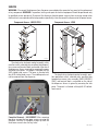
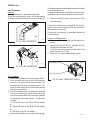
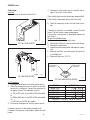
Faceplate Removal - H5 ELEMENT: After removing
top cover, remove the two upper screws securing the
faceplate. Carefully lift faceplate straight up until the
three lower screws clear the key holes.
The check valve, electronic control assembly, safety
overfl ow switch, solenoid valve, overfl ow tube tempera-
ture sensor and terminal block are located at the rear of
the dispenser. Access is gained by removing the upper
and lower rear panels. The upper is attached with six
8-32 slotted-head screws. The lower is attached with
four 8-32 slotted-head screws. The middle panel must
not be removed from the dispenser.
P1770.30
42311 022311
:$51,1*
9HU\+RW:DWHU
8VH:LWK&DUH
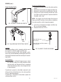
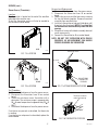
The check valve, electronic control assembly, over-
fl ow protection switch, solenoid valve, overfl ow tube
temperature sensor, triac assembly (EARLY MODELS
ONLY) and terminal block are located on the side of
the dispenser. Access is gained by removing the side
panel. The panel is attached with eight 8-32 slotted-
head screws.
P878.30
SERVICE
WARNING – Disconnect the dispenser from the power source before the removal of any panel or the replacement
of any component. WARNING - Inspection, testing, and repair of electrical equipment should be performed only
by qualifi ed service personnel. Disconnect the dispenser fromthe power source when servicing, except when
electrical tests are required and the test procedure specifi cally states to connect the dispenser to the power source.
Component Access - H5E/DV-PC/X Component Access - H10X

8
SERVICE
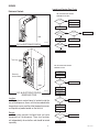
Electronic Controls
FIG. 8a ELECTRONIC CONTROL
P4093.35
Voltage present at
Solenoid Valve
?
Voltage present at
Solenoid Valve
?
Overflow Cup Full
?
Remove Power
Disconnect Level Probe
Retry
Drain cup
No
Yes
Yes
Yes
Yes
No
No
No
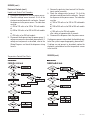
H5E, H5X LIQUID LEVEL CONTROL
PROBLEM: Does Not Refill
Does Water Flow
?
Replace Probe
Unplug Ready Lamp
Replace Ready Lamp
Replace Control Board
Replace Solenoid Valve
Overflow
?
Overflow
?
Retry
Drain cup
Yes
Yes
No
H5E, H5X LIQUID LEVEL CONTROL
PROBLEM: Overflows
Unplug Ready Lamp
Retry
Retry
Drain cup
Drain cup
Short Probe Wire
To Chassis
Disconnect Probe
Wire From Probe
Disconnect Wire From
Solenoid Valve
Replace Ready Lamp
No
Replace Probe
Overflow
?
Yes
Replace Control Board
No
Replace Solenoid Valve
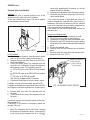
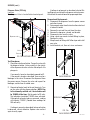
Location:
The electronic control board is located inside the
rear of the dispenser. Access will also be needed to the
temperature sensor, overfl ow tube temperature sensor,
and liquid level probe located on the tank lid.
General:
This system controls the liquid level and water
temperature of the dispenser. These two functions
act independently of each other and should be tested
separately.
Liquid Level Control Flow Charts
42311 071310
%811
SVLJPD[RSHUDWLQJSUHVVXUH
6WUDLQHU)ORZ&RQWURO
5HSO)ORZ:DVKHU
5HSO6FUHHQ
JSP)/2:
Triac Assy
Electronic
Control Board
P1991-1.30
FIG. 8b ELECTRONIC CONTROL
BOARD AND TRIAC
H 10
H 5

9
SERVICE (cont.)
Electronic Controls (cont.)
Liquid Level Control Test Procedure
1. Disconnect the dispenser from the power source.
2. Check the voltage across terminals 3 & 4 of the
electronic control board with a voltmeter. Connect
the dispenser to the power source. The indication
must be:
a.) 100 to 120 volts ac for 100 to 120 volt models
or
b.) 200 to 240 volts ac for 200 to 240 volt models
or
c.) 230 volts ac for 230 volt models.
3. Disconnect the dispenser from the power source. If
voltage was present as described, proceed to #4. If
voltage was not present as described, refer to the
Wiring Diagrams and check the dispenser wiring
harness.
4. Remove the pink wire from terminal 5 of the elec-
tronic control assembly.
5. Check the voltage across terminals 1 & 4 of the
electronic control board with a voltmeter. Connect
the dispenser to the power source. The indication
must be:
a.) 100 to 120 volts ac for 100 to 120 voltmodels
or
b.) 200 to 240 volts ac for 200 to 240 volt models
or
c.) 230 volts ac for 230 volt models
after a delay of approximately 5 seconds.
6. Disconnect the dispenser from the power source.
If voltage was present as described, the liquid level con-
trol of the system is operating properly, proceed to #7.
If voltage was not present as described, replace the
electronic control board and the temperature sensor
in the tank lid.
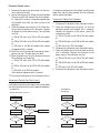
SERVICE (cont.)
Temperature Control Flow Charts
42311 071310

10
Electronic Controls (cont.)
7. Reconnect the pink wire to terminal 5 of the elec-
tronic control assembly.
8. Loosen the compression fi tting, remove the probe
from the tank lid, and inspect it for mineral depos-
its. Replace it if necessary. Keep the exposed ends
of the probe away from any metal surface of the
dispenser.
9. Check the voltage across terminals 1 & 4 of the elec-
tronic control assembly with a voltmeter. Connect
the dispenser to the power source. The indication
must be:
a.) 100 to 120 volts ac for 100 to 120 volt models
or
b.) 200 to 240 volts ac for 200 to 240 volt models
or
c.) 230 volts ac for 230 volt models after a delay
of approximately 5 seconds.
10. Touch the screw head end of the probe to the dis-
penser housing. The indication must be 0.
11. Move the probe away from the dispenser housing.
The indication must again be:
a.) 100 to 120 volts ac for 100 to 120 volt models
or
b.) 200 to 240 volts ac for 200 to 240 volt models
or
c.) 230 volts ac for 230 volt models
after a delay of approximately 5 seconds.
12. Disconnect the dispenser from the power source.
Temperature Control Flow Charts (cont.)
If voltage was present as described, reinstall the probe,
the sensing function of the system is operating properly.
If voltage was not present as described, check the pink
probe wire and the green ground wire for continuity
and/or replace the probe.
Temperature Control Test Procedure
1. Disconnect the dispenser from the power source.
2. Check the voltage across terminals 3 & 4 of the
electronic control circuit board with a voltmeter.
Connect the dispenser to the power source.The
indication must be:
a.) 100 to 120 volts ac for 100 to 120 volt models
or
b.) 200 to 240 volts ac for 200 to 240 volt models
or
c.) 230 volts ac for 230 volt models.
3. Disconnect the dispenser from the power source.
4. Check the voltage across the tank heater terminals
with a voltmeter. Connect the dispenser to the
power source. The indication must be:
a.) 100 to 120 volts ac for 100 to 120 volt models
or
b.) 200 to 240 volts ac for 200 to 240 volt models
or
c.) 230 volts ac for 230 volt models.
5. Disconnect the dispenser from the power source.
Still Boiling
?
Red Light On While
Boiling
?
Retry
Drain cup
Retry
Disconnect Blue Wire From
Control Board Pin 7
No
Yes
Yes
Yes
No
No
H5X THERMOSTAT
PROBLEM: Boils Excessively - Fills Cup
Still Boiling
?
Replace Steam Sensor
Replace Triac Assembly
Check For Split
Tank Heater
Replace Control Board
Finished
Replace Control Assembly
Still Boiling
?
Red Light On While
Boiling
?
Retry
Drain cup
Retry
Disconnect Blue Wire From
Control Board Pin 7
No
Yes
Yes
No
H5E THERMOSTAT
PROBLEM: Boils
Replace Triac Assembly
Check For Split
Tank Heater
Replace Control Board
Replace Control Assembly
42311 071310

11
SERVICE (cont.)
Electronic Controls (cont.)
If voltage was present as described, the temperature
control of the system is operating properly.
If voltage was not present as described, contact
Bunn-O-Matic to order an electronic control board and
temperature sensor for evaluation and proceed to #9.
6. Replace the electronic control board.
7. Check the voltage across the tank heater terminals
with a voltmeter. Connect the dispenser to the
power source. The indication must be:
a.) 100 to 120 volts ac for 100 to 120 volt models
or
b.) 200 to 240 volts ac for 200 to 240 volt models
or
c.) 230 volts ac for 230 volt models
8. Disconnect the dispenser from the power source.
If voltage was present as described, the temperature
control of the system is operating properly. Return the
new electronic control board or temperature sensor to
Bunn-O-Matic for credit.
Electronic Controls Removal and Replacement
1. Remove all wires from the electronic control board
terminals.
2. Remove the six 6-32 screws holding the electronic
control board to the component bracket.
3. Disconnect the temperature sensor, overfl ow tube
temperature sensor, and indicator wires from the
electronic control board.
4. Attach the temperature sensor, overflow tube
temperature sensor, and indicator wires to the
electronic control assembly.
5. Fasten the new electronic control board to its
bracket.
6. Refer to Fig 2 when reconnecting the wires.
7. Review the initial set-up procedures on page 6.
FIG. 11a WIRING CONNECTIONS
Adjustments
The H5X/H10X dispensers hold the water tempera-
ture at the threshold of boiling. It is not adjustable by
the user.
The H5E dispenser is factory calibrated for the
temperature specifi ed on the data plate. If adjustment
is required, use the following procedure:
1. Fill the dispenser according to the steps in the Initial
Set-up.
2. Take the temperature of the stream of water im-
mediately below the faucet as it fl ows from the
dispenser with an accurate thermometer. Do not
take the temperature of water collected in a con-
tainer.
3. If any adjustment is required, refer to LEVEL 1
PROGRAMMING in the Operating Manual.
J3 PNK & GRY to
Heater Indicator
Refi ll Indicator
Power Indicator
Ready Indicator
T5 PNK to Liquid
Level Probe
T4 WHI or RED to
Terminal Block
T3 BLK to Overfl ow
Safety Switch
T2 GRN or GRN/YEL
to Chassis Ground
T1 WHI/BLU to
Solenoid
J4 BLK & WHI to
Temperature Sensor
J5 GRY & GRY toTherm-
istor (H5X only)
BLU to Tank
Heater
WHI/VIO to
Terminal Block
42311 071310

12
SERVICE (cont.)
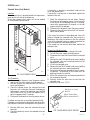
Limit Thermostat
Location:
The limit thermostat is located on the tank lid.
To test the limit thermostat, access will also be needed
to the terminal block located at the rear of the dispenser.
If voltage was present as described, reconnect the black
wire and proceed to #5.
If voltage was not present as described, refer to the Wir-
ing Diagrams and check the dispenser wiring harness.
5. Check for continuity across the terminals of the
limit thermostat.
If continuity is not present as described, the circuit is
broken. Press the reset button of the limit thermostat
and recheck for continuity.
If continuity is not present as described, replace the
limit thermostat.
Removal and Replacement:
1. Remove both wires from the limit thermostat ter-
minals.
2. Remove the two #10-32 nuts attaching the limit
thermostat to the top of the tank.
3. Install the new limit thermostat and secure into
place with two #10-32 nuts.
4. Refer to FIG. 4 when reconnecting the wires.
Test Procedure:
1. Disconnect the dispenser from the power source.
2. There are two black wires on the limit thermostat
terminals. One comes from the terminal block. The
other goes directly to the tank heater terminal. Re-
move the black wire at the limit thermostat coming
from the terminal block.
3. Check the voltage across the black wire removed
from the limit thermostat and the white wire or red
wire of the terminal block with a voltmeter. Connect
the dispenser to the power source. The indication
must be:
a.) 100 to 120 volts ac for 100 to 120 volt models
or
b.) 200 to 240 volts ac for 200 to 240 volt models
or
c.) 230 volts ac for 230 volt models.
4. Disconnect the dispenser from the power source.
FIG. 12a LIMIT THERMOSTAT
FIG. 12c LIMIT THERMOSTAT WIRING
BLK to Terminal Block
BLK to Tank Heater
P4093
P1776
Reset
P1993
FIG. 12b LIMIT THERMOSTAT
42311 071310
H 10
H 5

13
SERVICE (cont.)
Safety Overfl ow Switch
Location:
The safety overfl ow switch is located inside the rear of
the dispenser inside the copper overfl ow cup.
For testing or removal of the safety overfl ow switch,
access may also be needed by removing the two screws
attaching the electronic control assembly to its mount-
ing bracket.
Test Procedure:
1. Once voltage is verifi ed at the power source, check
for continuity across the safety overfl ow switch
red wires only until the plastic fl oat is raised and
check that continuity returns when the plastic fl oat
is again lowered.
If continuity is present as described, reconnect each
of the red wires to the black wires, the safety overfl ow
switch is operating properly.
If continuity is not present as described, replace the
safety overfl ow switch.
FIG. 13a SAFETY OVERFLOW SWITCH
FIG. 13c SAFETY OVERFLOW WIRING
RED to BLK Wire from
Terminal Block
RED to BLK Wire from Elec-
tronic Control #3
P4093
P1777
Removal and Replacement:
1. Disconnect the black wires from the safety overfl ow
switch.
2. Remove the nut beneath the copper overfl ow cup.
3. Remove the entire switch assembly from the cup.
4. Place the new switch assembly into the cup, wires
fi rst. Make sure that a gasket is in place around the
threaded switch stem.
NOTE - The magnets must be at the top of the fl oat and
there must be NO stainless steel washers installed for
the safety overfl ow switch to operate properly.
5. Install the nut beneath the copper overfl ow cup.
Be sure not to overtighten.
6. Reconnect the wires, FIG. 6.
P1993
FIG. 13b OVERFLOW PROTECTION SWITCH
42311 071310
H 10
H 5

14
SERVICE (cont.)
Solenoid Valve (Late Models)
Location:
The solenoid valve is located inside the rear of the
dispenser on the right side near the bottom.
To test the solenoid valve, access will also be needed
to the electronic control board.
sound after approximately 5 seconds, as the coil
magnet attracts the plunger.
8. Disconnect the dispenser from the power source.
9. Reconnect the pink wire to terminal 5 of the elec-
tronic control board.
If the sound was heard as described and water will
not pass through the solenoid valve, there may be a
blockage in the water line before or after the solenoid
valve or the solenoid valve may require inspection for
wear and removal of waterborne particles.
If the sound was not heard as described, replace the
solenoid valve.
Removal and Replacement:
1. Remove all wires from the solenoid valve coil.
2. Turn-off the water supply to the dispenser.
3. Disconnect the water line from the solenoid valve.
4. Remove the two 8-32 slotted-head screws holding
the solenoid valve and mounting bracket to the back
panel.
5. Lift-out the solenoid valve.
6. Securely install the new solenoid valve to the back
panel.
7. Securely fasten the water line to the solenoid valve.
8. Reconnect the wires, FIG. 8.
Fill
w
ater
t
an
k
bef
or
e
t
ur
ning
-on
t
hermo
s
ta
t
or
c
o
n
n
ecting
ap
pli
ance
t
o pow
e
r
sourc
e.
D
o no
t
us
e
ne
ar
c
ombustib
l
es.
Foll
o
w
nat
i
on
al
/
loc
al
e
l
ec
tric
al
c
o
des
.
Elect
r
ically
gr
ou
nd t
h
e c
has
s
i
s
.
Use on
l
y on a
pr
o
per
ly
pr
ot
ec
t
e
d
c
ir
c
uit capa
ble
of
t
he
r
at
ed
l
o
ad.
F
AILURE
TO
C
OMPLY R
ISKS
EQ
UI
PM
ENT
D
A
MA
G
E,
F
I
RE
,
O
R
SH
OC
K H
A
Z
AR
D
R
E
AD
TH
E
E
N
TI
R
E
OPE
R
A
TING M
A
N
UAL
I
N
CL
U
D
I
NG THE L
IMIT
OF
WARR
ANTY
A
N
D
L
IABILI
TY
BE
FOR
E
BU
Y
I
N
G
OR U
S
ING
TH
I
S
P
RO
D
U
C
T
THIS A
P
PLIA
N
CE
I
S
H
EATE
D
WHE
NEVE
R
C
ON
N
E
C
TE
D
T
O
A P
O
WE
R
SOU
RC
E
0
0
8
3
1
.
0
0
0
0
A
5
/8
8
©
19
8
8
B
U
N
N
-
O
-
M
A
T
IC
C
O
R
P
O
R
A
T
IO
N
WARNIN
G
!
Test Procedure:
1. Disconnect the dispenser from the power source
and turn-off the water supply to the dispenser.
2. Remove the pink wire from terminal 5 of the elec-
tronic control board.
3. Check the voltage across the solenoid valve coil
terminals with a voltmeter. Connect the dispenser
to the power source. The indication must be:
a.) 100 to 120 volts ac for 100 to 120 volt models
or
b.) 200 to 240 volts ac for 200 to 240 volt models
or
c.) 230 volts ac for 230 volt models
after a delay of approximately 5 seconds.
4. Disconnect the dispenser from the power source.
If voltage was present as described, proceed to #5.
If voltage was not present as described, refer to the Wir-
ing Diagrams and check the dispenser wiring harness.
5. Remove both wires from the solenoid valve coil
terminals.
6. Check for continuity across the solenoid valve coil
terminals.
If continuity is present as described, reconnect the wires
and proceed to #7.
If continuity is not present as described, replace the
solenoid valve coil.
7. Check the solenoid valve for coil action. Connect
the dispenser to the power source. Listen carefully
in the vicinity of the solenoid valve for a “clicking”
FIG. 14a SOLENOID VALVE
FIG. 14b SOLENOID VALVE WIRING
WHI/BLU to Electronic
Control Board T1
P1778
WHI or RED to
Terminal Block
42311 071310
H 5

15
Solenoid Valve (Early Models)
Location:
The solenoid valve is located behind the large access
panel on the left side of the dispenser.
To test the solenoid valve, access will also be needed
to the electronic control board.
BUNN
90 psig max operating pressure
Strainer/Flow Control # 22300.0750
(Repl. Flow Washer #20526.0750)
(Repl. Screen #23721.0000)
.750 gpm FLOW
P1994
FIG. 15a SOLENOID VALVE
SERVICE (cont.)
Test Procedure:
1. Disconnect the dispenser from the power source
and turn off the water supply to the dispenser.
2. Remove the pink wire from terminal 5 of the elec-
tronic control board.
3. Check the voltage across the solenoid valve coil
terminals with a voltmeter. Connect the dispenser
to the power source. The indication must be 200
to 240 volts ac for 200 to 240 volt models after a
delay of approximately 5 seconds.
4. Disconnect the dispenser from the power source.
If voltage was present as described, proceed to #5.
If voltage was not present as described, refer to the Wir-
ing Diagrams and check the dispenser wiring harness.
5. Remove both wires from the solenoid valve coil
terminals.
6. Check for continuity across the solenoid valve coil
terminals.
If continuity is present as described, reconnect the
wires and proceed to #7.
If continuity is not present as described, replace the
solenoid valve coil.
7. Check the solenoid valve for coil action. Connect
the dispenser to the power source. Listen carefully
in the vicinity of the solenoid valve for a “clicking”
sound after approximately 5 seconds, as the coil
magnet attracts the plunger.
8. Disconnect the dispenser from the power source.
9. Reconnect the pink wire to terminal 5 of the elec-
tronic control board.
If the sound was heard as described and water will
not pass through the solenoid valve, there may be a
blockage in the water line before or after the solenoid
valve or the solenoid valve may require inspection for
wear and removal of waterborne particles.
If the sound was not heard as described, replace the
solenoid valve.
Removal and Replacement:
1. Remove all wires from the solenoid valve coil.
2. Turn off the water supply to the dispenser.
3. Disconnect the water lines to and from the solenoid
valve.
4. Remove the two 8-32 slotted-head screws holding
the solenoid valve and mounting bracket to the
component bracket.
5. Lift out the solenoid valve.
6. Remove the two 10-32 slotted-head screws holding
the solenoid valve to its mounting bracket.
7. Securely install the new solenoid valve to its mount-
ing bracket. The direction of fl ow arrow must be
pointing towards the tank lid.
8. Attach the solenoid valve and mounting bracket to
the component bracket.
9. Securely fasten the water lines to and from the
solenoid valve.
10. Reconnect the wires, FIG. 8.
WHI/BLU to Contol
Board T1
RED to Terminal Block
RED to Control Board T4
P1779
FIG. 15b SOLENOID VALVE WIRING
42311 071310
H 10

16
SERVICE (cont.)
Tank Heater
Location:
The tank heater is located in the tank lid.
Test Procedure:
1. Disconnect the dispenser from the power source.
2. Check the voltage across the terminals of the tank
heater with a voltmeter. Connect the dispenser to
the power source. The indication must be:
a.) 100 to 120 volts ac for 100 to 120 volt models
or
b.) 200 to 240 volts ac for 200 to 240 volt models
or
c.) 230 volts ac for 230 volt models.
3. Disconnect the dispenser from the power source.
If voltage is present as described, proceed to #4.
If voltage is not present as described, replace the tank
heater.
FIG. 16a TANK HEATER
FIG. 16c TANK HEATER WIRING
BLK to Limit
Thermostat
BLU to Control
Board Relay
P1780
P4093
4. Remove the tank heater from the tank lid and in-
spect it for cracks in the sheath.
If the sheath shows no sign of damage, proceed to #5.
If the sheath is damaged, replace the tank heater.
5. Check for continuity across the tank heater termi-
nals.
If continuity is present as described, reinstall the tank
heater. The tank heater is operating properly.
If continuity is not present as described, replace the
tank heater.
Removal and Replacement:
1. Remove the wires to the tank heater.
2. Remove the 8-32 nuts from the tank heater fl ange.
3. Remove the tank heater.
4. Inspect the tank heater gasket and replace if neces-
sary.
5. Securely install the new tank heater. Be certain of
a watertight seal.
6. Reconnect the wires, FIG. 10.
P1993
FIG. 16b TANK HEATER
42311 071310
1800W-120V 07.44 - 08.67
4000W-240V 13.43 - 15.51
4000W-208V 10.09 - 11.99
6000W-240V 08.85 - 10.23
6000W-208V 06.67 - 07.70
HEATER RESISTANCE
TERMINAL TO SHEATH - INFINITE (OPEN)
H 10
H 5

Steam Sensor (Thermistor)
Location:
The thermistor is located on the end of the overfl ow
tube above the overfl ow cup.
To test the thermistor, access will also be needed to
the electronic control board.
SERVICE (cont.)
P1993
FIG. 17b LOCATION
H 10X
P1993
FIG. 17a LOCATION
H 5X
Test Procedure:
1. Disconnect the dispenser from the power source.
2. Disconnect the thermistor from J5 on control
board.
3. Check the resistance across thermistor with a
ohmmeter. The resistance range is approximately
9K @ room temperature to approximately 2K @
200°F.
4. Disconnect the dispenser from the power source.
If resistance was present as described, the thermistor
is working.
If resistance was not present as described, replace the
control board.
Removal and Replacement:
1. Disconnect the dispenser from the power source.
2. Disconnect the thermistor from J5 on control
board.
3. Loosen the set screw and the two screws securing
the two half blocks together. Remove thermistor
assembly from overfl ow tube.
4. Install new thermistor on tube and slide down until
it contacts the fl ared end. NOTE: It’s critical that
the thermistor be centered directly under the tube
opening.
5. Snug the set screw so the block assembly does not
move aroung easily.
6. Connect the thermistor to J5 on control board.
NOTE: DO NOT TEST OPERATION WITH PANELS
REMOVED, AS AIR MOVEMENT CAN HINDER
PROPER READINGS ON THERMISTOR.
Thermistor centered
under tube opening
FIG. 17d THERMISTOR POSITION
42311 080510
Set screw
Mounting screws
DO NOT BEND
THERMISTOR
UP/DOWN
FIG. 17c STEAM SENSOR EXPLODED
17

SERVICE (cont.)
Dispense Valve (PC Only)
Location:
The Dispense Valve is located behind control panel.
Test Procedures:
1. Check the valve for coil action. Turn on the valve with
the dispense button. Listen carefully in the vicinity
of the dispense valve for a click as the coil pulls the
plunger in.
If no sound is heard as described, proceed to #2.
If the sound is heard as described, there may be a
blockage in the valve. Disconnect the dispenser from
the power source. Remove the valve and inspect for
blockage, and de-lime all related areas.
2. Connect voltmeter leads to the coil terminals. Turn
on the valve with the dispense button. NOTE: Due
to the internally rectifi ed coil, the indication will
be 120VAC all the time. Set the meter to DC volts.
The indication should be 170VDC when activated.
If the polarity of meter leads are reversed, reading
will indicate -170VDC. (Double these readings for
240 volt coils)
If voltage is present as described, but no coil action
is observed, valve is defective. Replace valve and test
again to verify repair.
FIG. 18a DISPENSE VALVE
If voltage is not present as described, refer to Wir-
ing Diagrams and check the dispenser wiring harness.
Also check the control board for proper operation.
Removal and Replacement:
1. Disconnect the dispenser from the power source
and allow to cool.
2. Drain enough water from the tank so the water level
is below the outlet.
3. Remove the nut and fl are nut from the valve.
4. Remove the top cover, shroud, and bracket.
5. Disconnect wires from the valve.
6. Using a back up wrench to hold fi tting in place,
Remove the valve.
7. Wrap threads of fi tting with Tefl on tape and install
new valve.
8. Install bracket, nut, fl are nut, wires and covers.
42311 071310
REPAIR KIT
FIG. 18b
VALVE REMOVAL
Flare nut
Nut
Dispense valve
Bracket
Shroud
FIG. 18c
VALVE REPAIR KIT
18

42311 071310
19
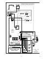
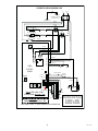
RELAY
N.O.
COM
3
1
5
4
2
FACTORY
J1-1
J1-5
H5-PC
NO JUMPER
Early H5E, H5X, H10X
Install jumper thru ver. 1.04
J3-1
J3-5
J5-1
J4-1
J6-1
NOTE: no jumper used on any
Model starting with ver. 1.08
J2
J7
MAIN
CONTROL
BOARD
12
34
+
-
+
-
USED ON
H5X ONLY
120V AC 2 WIRE + GND
120/208V AC 3 WIRE + GND
120/240V AC 3 WIRE + GND
SINGLE PHASE
PINK-22
BLK-24
WHI-24
TANK
t°
39333.0000D 09/09
©2006
BUNN-O-MATIC
CORPORATION
0-13.8VAC
0-3.3VDC
0-3.3VDC
GRY
GRY
t°
STEAM SENSOR
+
-
SCHEMATIC WIRING DIAGRAM H5E-DV PC
GRN-18
1
6
5
10
USE ONLY
Power
Heater
Ready
MEMBRANE SWITCH ASSY
STATIC
SHIELD
Left Dispense
Middle Dispense
Right Dispense
Manual Dispense/Stop
“Hidden” Switch
L1
WHT-14
WHT-18
WHT-18
1800 W
TANK HEATER
RED-14
BRN-14
WHI/VIO-14
VIO-18
BLK-18
WHI/BLU-18
120VAC
120VAC
WHI-18
4000 W
TANK HEATER
L2N
MASTER ON/OFF
SWITCH
BLK-14
RED-14
BLU-14
SELECTOR
SWITCH
BLK-14
LIMIT
THERMOSTAT
OVERFLOW
PROTECTION SWITCH
BLK-14
BLK-18
N.C.
REFILL
DISPENSE
SOL
SOL
GRN
Chassis Ground
Earth Ground

42311 071310
20
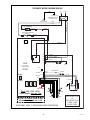
230V AC 2 WIRE + GND
SINGLE PHASE
RELAY
N.O.
COM
3
1
5
4
2
FACTORY
J1-1
J1-5
H5-PC
NO JUMPER
Early H5E, H5X, H10X
Install jumper thru ver. 1.04
J3-1
J3-5
J5-1
J4-1
J6-1
NOTE: no jumper used on any
Model starting with ver. 1.08
J2
J7
MAIN
CONTROL
BOARD
12
34
+
-
+
-
USED ON
H5X ONLY
PINK-22
BLK-24
WHI-24
TANK
t°
39333.0001C 10/09
©2006
BUNN-O-MATIC
CORPORATION
0-13.8VAC
0-3.3VDC
0-3.3VDC
GRY
GRY
t°
STEAM SENSOR
+
-
SCHEMATIC WIRING DIAGRAM H5E-PC
GRN-18
1
6
5
10
USE ONLY
Power
Heater
Ready
MEMBRANE SWITCH ASSY
STATIC
SHIELD
Left Dispense
Middle Dispense
Right Dispense
Manual Dispense/Stop
“Hidden” Switch
L1
RED-18
RED-18
RED-14
BLU-14 BLU-14
VIO-18
BLK-18
WHI/BLU-18
230VAC
230VAC
RED-18
4000 W
TANK HEATER
L2
BLK-14
RED-14
BLK-14
LIMIT
THERMOSTAT
OVERFLOW
PROTECTION SWITCH
BLK-14
BLK-18
N.C.
LIMIT
THERMOSTAT
REFILL
DISPENSE
SOL
SOL
GRN
Chassis Ground
Earth Ground
EMI
FILTER
Page is loading ...
Page is loading ...
Page is loading ...
Page is loading ...
-
 1
1
-
 2
2
-
 3
3
-
 4
4
-
 5
5
-
 6
6
-
 7
7
-
 8
8
-
 9
9
-
 10
10
-
 11
11
-
 12
12
-
 13
13
-
 14
14
-
 15
15
-
 16
16
-
 17
17
-
 18
18
-
 19
19
-
 20
20
-
 21
21
-
 22
22
-
 23
23
-
 24
24


Ask a question and I''ll find the answer in the document
Finding information in a document is now easier with AI
Related papers
-
Bunn H5X User manual
-
Bunn H5X Element Copper Owner's manual
-
-
-
Bunn DV PC User manual
-
-
-
-
-
Other documents
-
Bunn-O-Matic 39100.0001 User manual
-
Bunn-O-Matic 02550.0003 User manual
-
-
Bunn-O-Matic 39100.0005 User manual
-
-
-
Bunn-O-Matic H5X-40-208 Datasheet
-
-
-