GE GEH50DEEDSRA Owner's manual
- Category
- Water heaters & boilers
- Type
- Owner's manual
This manual is also suitable for

GEAppliances.com
-(:3
rY
L)
L_
U
Iii
-(:3
L_
"p..
0
I,.9
Important Safety Information ...2-4
Operating Instructions
Control Panel ..........................................5
Powering Unit .........................................6
Temperature Setting ............................7
OpemtionQl Modes ...............................8
FrequentlyAsked Questions(FAQ)..9
ApplianceCornrnunicotion
Module (ACM).......................................10
Care and Cleaning ....................11, 12
Installation Instructions .........13-18
Troubleshooting Tips ...............19-21
Consumer Support ...........................72
*ENERGY STAR@labeled product
ENERGYSTAR
As an ENERGYSTAR®partner, GEhas
determined that this product meets
the ENERGYSTAR®guidelines for
energy efficiency.
Write the model and serial
numbers here:
Model #
Serial #
Youcan find them on the rating label
on the front side ofyour water heater.
G EH50D EEDXX
Chauffe-eau
rGsidentiel hybride 61ectrique
La section frangaisecommence _ la page 25
Calentadores
de agua
residencieles elGctricos hibridos
La secci6n en espafiol empieza en la p6gina49
49-50281-2 02-12 GE

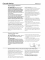
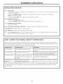
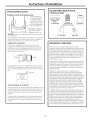
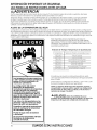
IMPORTANT SAFETY INFORIV/AT/ON.
READ ALL INSTRUCTIONS BEFORE USING.
A WARNING!
Foryour safety,the information in this manual must be followed to minimize the risk of fire or explosion,electric shock, or to
prevent property damage, personal injury, or lossof life.
Be sureto read and understand the entire Owner's Manual before attempting to install or operate this water heater. It may
save you time and cost. Payparticular attention to the Safety Instructions. Failureto follow these warnings could result in
serious bodily injury or death. Should you have problems understanding the instructions in this manual, or have any questions,
STOPand get help from a qualified servicetechnician or the local electric utility.
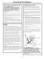
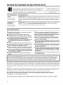
WATER TEMPERATURE ADJUSTMENT
Safety and energy conservation are factors to be considered when selecting the water temperature setting via the water
heater's user interface. Water temperatures above 125°Fcan cause severe burns or death from scalding. Besure to read
and follow the warnings outlined on the label pictured below. Thislabel is also located on the water heater near the top of the
tank.
HOT
Water temperature over 125°F can
cause severe burns instantly or
death from scalds.
The electronic temperature control
setting usually approximates tap
water temperature. However,
factors could cause water
temperature to reach 160°F
regardless of the control setting.
Always feel water before bathing
and showering.
Children, disabled and elderly are
at highest risk of being scalded.
See instruction manual before
setting temperature at water
heater.
Feel water before bathing or
showering.
Temperature limiting valves are
available; see manual.
Mixing valvesfor reducing point-of-use water temperature by
mixing hot and cold water in branch water linesare available.
Contact a licensedplumber or the local plumbing authority for
further information.
Time/Temperature Relationship in Scalds
(Temperature
120°F (49°0
125°F (52°0
150°F (54°0
155°F (57°0
140°F (6O°0
145°F (63°0
150°F (66°0
155°F (68°C)
Tablecourtesy of ShrinersBurnInstitute
Time t0 Pr0duce a SerioUS BUm
More than 5 minutes
1-1/2 to 2 minutes
About 30 seconds
About 10seconds
Lessthan 5 seconds
Lessthan 3 seconds
About 1-1/2 seconds
About 1 second
Thechart shown above may be usedas a guide in determining
the proper water temperature for your home.
Thermostat has been set at the factory to 120°F(49°0 to
reduce the risk of scald injury.
NOTE:Households with small children, disabled or elderly
persons may require a 120°F(49°C)or lower thermostat
setting to prevent contact with "HOT" water.
A DANGER: Thereis a Hot Water SCALDPotential
if the controlwater temperature isset too high.
SAVETHESEINSTRUCTIONS

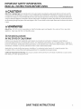
IMPORTANT SAFETY INFORMATION.
READ ALL INSTRUCTIONS BEFORE USING.
GEAppliances.com
A CAUTION!
Risk of Fire- Hydrogen gas can be produced in a hot water system served by this water heater that has not been used for
a long period of time (generally two weeks or more). HYDROGENGAS ISEXTREMELYFLAIVIIVIABLE!!To dissipate such gas and
to reduce risk of injury, it is recommended that the hot water faucet be opened for several minutes at the kitchen sink before
using any electrical appliance connected to the hot water system. Ifhydrogen is present, there will be an unusual sound such
as air escaping through the pipe as the water begins to flow. Do not smoke or use an open flame near the faucet at the time it
is open.
A WARNING!
Risk of Fire - DO NOTstore or use gasoline or other flammable vapors and liquids in the vicinity of this or any other
appliance. Keep rags and other combustibles away.
A FORINSTALLATIONS
IN THE STATE OF CALIFORNIA
California Law requires that residential water heaters must be braced, anchored or strapped to resist falling or
horizontal displacement due to earthquake motions. Forresidential water heaters up to 52 gallon (2:36.4L)capacity, a
brochure with generic earthquake bracing instructions can be obtained from: Office of the State Architect, 400 PStreet,
Sacramento, CA95814 or you may call 916.324.5315 or ask a water heater dealer.
Applicable local codes shall always govern installation. For residential water heaters of a capacity greater than
52 gallons (2:36.4L)consult the local building jurisdiction for acceptable bracing procedures.
California Proposition 65 Warning: This product contains chemicals known to the State of California to cause cancer,
birth defects or other reproductive harm.
SAVETHESEINSTRUCTIONS 3

IMPORTANT SAFETY INFORMATION.
READ ALL INSTRUCTIONS BEFORE USING.
A WARNING:
If the water heater has been
subJectedto flood, fire, orphysical
damage,turn off power and water
to the water heater.
Do not operate the water heater
again until it has been thoroughly
checked by qualified service
personnel.
Safety Precautions
A.Do turn off power to water heater if
it hasbeen subjectedto overheating,
fire, flood or physical damage.
B.Do Not turn on water heater unless
it isfilled with water.
C.Do Not turn on water heater ifcold
water supply shut-off valve is closed.
NOTE:Flammable vapors may be drawn
by air currents from surrounding areas
to the water heater.
D. Ifthere isany difficulty in understanding
or following the Operating Instructions
or the Careand Cleaningsection, it is
recommended that a qualified person
or serviceman perform the work.
Safety Controls
Thewater heater isequipped with a
temperature-limiting control (TCO)that
islocated abovethe heatingelement in
contact with the tank surface.Ifforany
reasonthe water temperature becomes
excessivelyhigh,thetemperature-limiting
control (TCO)breaksthe power circuitto
the heatingelement.Oncethe control
opens,it must bereset manually.Resetting
of thetemperature limitingcontrolsshould
bedone by aqualifiedservicetechnician.
A CAUTION: Thecause
of the high temperature condition must
be investigated by a qualified service
technician and corrective action must
be taken before placing the water heater
in serviceagain.
To reset the temperature-limiting
control:
1. Turn off the power to the water
heater.
2.
Remove the jacket access panel(s)
and insulation.
The thermostat protective cover
should not be removed.
3. Press the red RESETbutton.
4. Replace the insulation and jacket
access panel(s) before turning on
the power to the water heater.
4 SAVETHESEINSTRUCTIONS

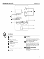
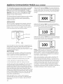
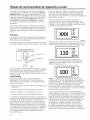
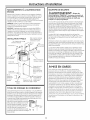
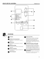
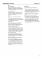
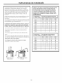
About the controls. GEAppliances.com
O
0
O
I
oF
DAYS
-31HEAT PUMP IONLVl
OHYBRID
OHIGH DEMAND
_ELECTRIC IFANom
_,VACATION
3
EA_U
Hold for Hold to Override
°F/°C PS-Power Saver
I
A
O
I
kT
Hold to
Reset
J
0
O
0
O
(_ Co_ntrol_s
O Display
O Operating Modes
(Seepage 8 for description)
Vacation
(Seepage 8 for description)
O Mode Selector
Usethis button to alternate between
available modes.
O
Arrow Pads
Usethis button to adjust the temperature
setting.
O Enter Key
0
0
O
Filter Reset
Thefilter isdirty and requires cleaning when
the Redlight isilluminated. Filter is located
on top of the water heater. Pressbutton and
hold for 5 seconds to reset filter alarm.
Power Saver Override
For usewith ACIVlmodule. Pressand hold to
bring unit out of Power Saver mode. Once
pressed and Power Savermode iscancelled,
unit will remain out of Power Saverfor the
next 18 hours.
Appliance Communication
Module Port
For usewith optional ACIVlmodule (seepage
10 for details).

Turning on the water heater.
There is no power button for this unit. Once the
water heater is wired and power issupplied, it
will be on. Thedisplay will show the current water
temperature setting. Current operating mode for
the water heater is illuminated.
To comply with safety regulations, the controls are
factory preset to 120°F(49°C)and Hybrid IVlode.It
is recommended that the unit be set to Heat Pump
(only)mode to maximize energy savings. Operating
in Hybrid mode provides a balance of energy
savings and hot water use convenience. Reported
energy consumption isbased on operating the unit
in Hybrid mode at a temperature setting of 135°F
(57°C),and operation at lower temperature settings
or in Heat Pump (only)mode will provide even
greater energy savings.
oF
oC
DAYS
OHEAT PUMP IoNLYI
OHYBRID
eHI6H DEMAND
• ELECTRIC{FANOFF)
•VACATION
Hold for
°F/° C
VE_
Hold to Override
PS-Power Sorer
T
LT
Hold to
Reset
6

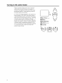
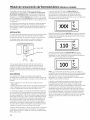
About the water temperature setting. GEAppliances.com
Temperature setpoint:
Safety,energy conservation and hot water capacity
are factors to be consideredwhen selectingthe
water temperature settingof the water heater.To
comply with safety regulations,the water temperature
setpoint isfactory set at 120°F(49°0.Thisisthe
recommended starting temperature setting.
NOTE:According to USDeptof Energy,the average
residentialwater heater in the USisset at 135°F(57°0.
GEGeoSpringTM Hybrid Water Heater'senergy savings
claimsare basedon a 135°F(57°0 temperature
setting.Thewater temperature setpoint can be raised
from the factory setting of Z20°Fto Z35°F(49°Cto
57°0 without sacrificing the claimedenergy savings.If
a lowertemperature setting than 135°F(57°0 isused,
greater savingsin energy andoperating costs may be
achieved.
See"ToAdjustthe Temperature" below to change the
water heater'stemperature.
Hot water capacity:
Ifmore hot water capacity isdesired,increasingthe
temperature from 120°Fto 135°F(49°Cto 57°Gwill
enable the sametank of hot water to last about 25%
longer becausemore coldwater ismixed inat the
shower orfaucet.
Risk of Scalding Reminder:
Water temperatures above 125°F152°C)can cause
severe burnsor death from scalding.Besureto read
and follow the warnings outlined in this manual and
on the label on the water heater. Thislabelis located
on the water heater near the upper element access
panel.
See"Time/TemperatureRelationshipin Scalds"
belowas a guide indetermining the proper water
temperature for your home.
Mixing-valves:
Mixingvalvesfor reducing point-of-use water
temperature bymixing hot and cold water in branch
water linesare available.Contact alicensed plumber
or the local plumbing authority for further information.
A DANGER: Thereisahotwaterscald
potential if thewater temperature isset too high.
Householdswith small children,disabled,or elderly
persons mayrequire a 120°F(49°C)or lower
thermostat setting to prevent contact with HOTwater.
Time/Temperature Relationship in Scalds
Temperature.
120°F (49°0
125°F (52°0
130°F (54°0
13S°F (57°0
140°F (6O°0
145°F (63°0
150°F (66°0
155°F (68°0
TablecourtesyofShrinersBurninstitute
More than 5 minutes
1-1/2 to 2 minutes
About 30 seconds
About 10 seconds
Lessthan 5 seconds
Lessthan 3 seconds
About 1-1/2 seconds
About i second
To Adjust the Temperature
Follow these steps:
1.Press the UPor DOWN arrow on the control
panel key pad to desired temperature.
2. Press ENTERto accept the new setting.
Note: To change between °Fand °C,press and
hold MODE
A DANGER: ThereisaHotWaterscald
Potential if the water temperature is set too high.
120°F(49°C)is the recommended starting point for
water temperature setting, but it can be adjusted
to any temperature between IO0°F and 140°F (38°C
and 60°CL
oF
oc
DAYS
• HEATPUMP(ONLY)
• HYBRID
• HIGHDEMAND
• ELECTRIC(FAN OFF)
•VACATION
A
T
V
_OD 9 L.S.AVEU_POWIER-'__ILT•ER_
Hold for Hold to Override Hold to
°F/°C PS Power Saver Reset
7

Operational Modes.
This water heater defaults to the Hybrid operating
mode. Available modes are listed below and can
be selected using the MODEbutton.
Heat Pump (only) Mode--RECOMMENOED FOR
MAXIMUMSAVINGS
Heat Pump (only) is the most energy-emcient
mode for this water heater. It takes heat from
the surrounding air to heat the water. The time it
takes to heat the water is longer in this mode, so
it may not be sumcient if you have a high-demand
situation such as a large household or company.
Hybrid Mode
Hybrid mode combines the energy efficiency of
Heat Pump (only)with the recovery speed and
power of the Electric (Fanoff)/Standard (Fanoff)
mode in most water usage situations. Hybrid
mode will allow the unit to perform like a standard
electric water heater while providing significant
energy savings.
NOTE: Reported unit performance, energy
consumption and savings are based on Hybrid
Mode operation at a temperature setting of 135°F
(57°C).
High Demand/Boost
This mode may be necessary if your household
has a higher-than-average water usage or the unit
isundersized for the household water demands.
Inthis mode, the unit will use the electric heating
elements only when the water demand rate is
high. When using the heating elements, the water
temperature will recover at a faster rate but it will
use more energy to heat it. Unlike Electric (Fanoff)/
Standard (Fan off) mode, it will use the heating
elements only when needed, and use the heat
pump when water demand rates are lower.
NOTE: The difference between Hybrid mode
and High Demand mode is that in High Demand
mode the heating resistive elements are activated
sooner than in the Hybrid mode.
Electric (Fan off)/Standard (Fan off) Mode
This mode uses only the upper and lower heating
resistance elements to heat the water. The time it
takes to heat the water is less in this mode, but it
isthe LEASTenergy-efficient mode.
Vacation
Thisfeature is used when you will be away from
the home for an extended period of time and hot
water isnot needed. Inthis mode, the unit will drop
the water temperature down to 50°F (10°C)and will
use the most efficient heating mode to conserve
energy while the heater issitting idle.The unit will
automatically resume heating one day before your
return, sothat hot water will be available.
For example if you will be gone 14 days, follow
these steps:
1. Select VACATIONby using the Mode button
2. Input total days you will be gone (in this
example, 14) by pressing the UParrow button
(the default is 7 days)
3. Press ENTER.
The unit will drop the water temperature down to
50°F (10°C)for one day less than you will be gone
(in this example, for 1:5days).At the end of the
day before you return (in this example, the 13th
day), it will automatically return to the previous
operating mode and heat the water to the original
temperature setting so hot water is available
upon your return.
To access any of these modes:
F_-]Press the MODEbutton on the control to the
desired operating mode.
[] The green light will be illuminated on the
chosen mode.
8

Frequently Asked Questions. GEApplionces.com
Filten
O:Whyistherea filter?
A:inHybridandHeatPump(only)theunitmovesair
throughthesystem.Thefilter protectstheunitfromdirt.
Acleanairfilterimprovesefficiency.
O:Howtocleanthefilter?
A:Leavepoweronand removefilterfromtopofunit.Filter
canbevacuumedcleanor rinsedwith warmwater.A
dirtyfilterwillreducewaterheaterefficienc!!
Modes:
O:WhatisHeatPump(only)?
A:HeatPump(only)isthemost-efficientmode.Ittakes
heatfrom
theairto heatwater,therebycoolingthesurrounding
air.Slowerrecoverybutmost-efficientmode.
O:WhatisHybrid?
A:TheHybridmodecombinesbenefitsofHeatPump(only)
withthespeedandpowerofStandardElectric.This
providesgreatperformancewithlessenergy.
Q:WhatisHighDemand/Boost?
A:HighDemand/Boostcanbeusedwhenhotwaterusage
ishigherthannormal.Theunitwillbe lessefficientbut
willheatwaterfasterin responseto longwaterdraws.
Forallnormaldraws,theunitwillstillusetheefficient
HeatPumpthemajorityofthetime.
Q:WhatisVacationmode?
A:Ifyouaregonefor anextendedperiod,thismode
lowersthewatertemperatureto reduceenergyused.
Unitwillswitchto thepreviousmodeonedaybefore
yougetback.
Q:WhatisElectric(Fanoff)/Standard(Fanoff)?
A:Electric(Fanoff)/Standard(Fanoff)modeusesonlythe
resistanceheatersto heatthewater.Thisgivesfaster
hotwater recoverythanHybridmode,butusesmore
energy.Thismodeoperateswithoutthefan,stopping
thecoolair normallydischargedduringheatpump
operation.
Operation:
O:WhycanIhearthe unitrun?
A:Inthe mostenergy-efficientmodes,HeatPump(only),
Hybrid,andHighDemand/Boost,themethodused
toheatthewater usesafanthat canbeheardwhile
running.
O:Theheatpumpisnotrunningitsnormallengthoftime.
Whatcausesthis?
A:Undersomeconditions,theGeoSpringTM HybridWater
Heaterwilloperateusingtheelectricelementsinsteadof
theheatpumpto protectyourunitandensurehotwater
isavailabletoyou. Theseconditionsincludeextreme
coldambienttemperature(</45°F),extremehotambient
temperatures(>:].20°F),or verylowvoltageconditions.
Theunitwillreturnto normaloperationwhenconditions
permit.

ApplianceCommunicationModule(where installed).
The Hybrid Electric heat pump water heater is compatible
with the GE Smart Appliance communication module
(ACM)which can be purchased separately. Contact
your local utility or visit www.GEAppliances.com/Smart-
Appliance to see if your area is using ACM technology.
Applying the ACIvi allows the unit to respond to utility
signals or to join a home network.
Thefollowing demand response features may be available
as part of a pilot test program with the local utility
company to help consumers reduce peak electricity
usage in the home.
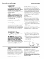
When the ACM signal isMedium, the control will operate
in Heat Pump (only) Mode and the water temperature will
remain at the current user setting. The screen will display
the following (where xxx isthe current user temperature
setting):
INSTALLATION
TheACM module is equipped with magnets in the base
of the module that will enable it to be attached to the
painted metal exterior of the heat pump water heater.
Details on how to connect the cables to the module are
in the instructions that come with the module.
Once the cable from the ACM module is plugged into the
water heater's connection, follow the power-up directions
included with the ACM module. As soon as the ACM
module is operating, the heat pump water heater is ready
to receive the ACM signals.
QUICK GUIDE
If your local utility company is utilizing ACMtechnology,
the ACM module will receive the signals sent from your
utility company. One of four signals will be sent:
• "Low" (represents lowest energy cost rate is available)
• "Medium" (represents increased energy cost rate)
• "High" (represents increased energy cost rate)
• "Critical"(represents "peak rate" energy cost rate)
A heat pump water heater equipped with a ACM module
will automatically recognize what energy cost rate is
available and adjust its mode and temperature setting to
use less energy when rates are medium, high and critical.
When the heat pump water heater responds to these
signals, the LEDlight above the Power Saver button will be
on, indicating energy pricing periods are in effect, and the
letters PSwill be displayed on the LEDif the user attempts
to change the temperature without first pressing the
Power Saver override button.
When the signal is low or when no ACM module is
connected, the unit runs as normal. The following steps
show how the unit reacts to Medium, High and Critical
signal levels.
When the ACM signal isHigh, the control will operate in
Heat Pump (only)mode, with a water temperature setting
of Zl0°F (43°C),and the screen will display:
When the ACM signal isCritical, the control will operate in
Heat Pump (only)mode, with a water temperature setting
of Z00°F (38°C),and the screen will display:
_n
oF
1
Notice: Appliance ACM connection carries voltage not
compatible to computers or accessories. Do NOT plug
laptops, modems, routers, etc into the Appliance RJ45
ACM connector. Use only with designated GEAppliance
Accessories. Connection to computers and accessories
may result in product damage.
When unit isoperating in medium, high or critical,the LCD
above the PowerSaverbutton will be lit. If at any time you
want to change the temperature setpoint while the unit isin
PowerSavermode, pressand hold the PowerSaver button to
overridethe PowerSaver mode,then usethe arrow buttons
to change to the desired setting. Overridewill be in place
for Z8hours. Ifyou try to change the temperature without
overriding the powersaver function, the letters PSwill show on
the display,indicating it isstill in Powersavermode.
10

Care and cleaning. GEAppliances.com
Routine Preventive Maintenance
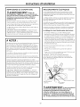
A DANGER:RiskofScald-Before
manually operating the relief valve, make
certain no one will be exposed to the danger of
coming in contact with the hot water released
by the valve. The water may be hot enough to
create a scald hazard. The water should be
released into a suitable drain to prevent injury or
property damage.
NOTE: If the temperature and pressure-relief
valve on the hot water heater discharges
periodically, this may be due to thermal expansion
in a closed water system. Contact the water
supplier or your plumbing contractor on how to
correct this. Do not plug the relief valve outlet.
Properlymaintained, your water heater will provide
years of dependable trouble-free service.
It issuggestedthat a routine preventive maintenance
program be established andfollowed bythe user.
Temperature and Pressure-Relief Valve:
At least once a year, liftand release the lever handle
on the temperature and pressure-relief valve, located
on the front-right side of the water heater, to make
certain the valve operates freely. Allowseveral
gallons to flush through the discharge line to an
open drain.
Periodic Inspection (once a year):
It isfurther recommended that a periodic inspection
of the operating controls, heating elements and
wiring should be made by servicepersonnel
qualified in electricappliance repair.
Most electrical appliances,even when new, make
some sound when in operation. Ifthe hissing or
singing sound levelincreasesexcessively,the electric
heating element may require cleaning. Contact a
qualified installer or plumber for inspection.
Flushing Tank:
A water heater'stank can act asa settling basin
for solids suspendedin the water. It istherefore not
uncommon for hard water depositsto accumulate
in the bottom of the tank.Toclean the tank ofthese
deposits,follow these steps:
1.Attach a garden hose to the drain valve located
at the bottom of the unit and direct that hoseto a
drain.
2.Open the drain valve with aflat screwdriver.
3.Onceo few quarts of water have been drained,
close the drain valve.
Thisshould be donewith the cold water supply
open such that water removed through drain valve
is replaced,and water supply flow helpsto remove
sediment.
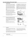
Draining the Water Heater
A CAUTION: Risk of Shock- Shut off
power to the water heater before draining
water.
A DANGER:RiskofScald-Before
manually operating the relief valve, make certain
no onewill be exposedto the hot water released by
the valve. Thewater drained from the tank may be
hot enoughto present a scald hazard and should
be directed to a suitable drain to prevent injury or
damage.
To drain the water heater, follow these steps:
1. Attach a garden hose to the drain valve located
at the bottom of the unit and direct that hose
to a drain.
2.Turn off the cold water supply.
3. Admit air to the tank by opening u hot water
faucet or lifting the handle on the relief valve
4. Open the drain valve with a fiat screwdriver.
Note: See page 15 for product schematic.
I 9 1-
/ _ screwdriver
_ to turn
valve.
Extended Shutdown Periods or Vacations Exceeding Vacation Mode Options
If the water heater isto remain idle for an
extended period of time, the power and water to
the appliance should be turned off to conserve
energy and prevent a buildup of dangerous
hydrogen gas. This unit has no power button,
power can only be shut off at the circuit breaker
or disconnect switch.
The water heater and piping should be drained if
they might be subjected to freezing temperatures.
After a long shutdown period, the water heater's
operation and controls should be checked by
qualified service personnel. Make certain the
water heater iscompletely filled again before
placing it in operation.
NOTE:Refer to the Hydrogen GasCaution
in the Operating Instructions (seepage 3).
11

Care and cleaning of the water heater.
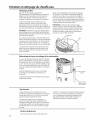
Cleaning the Filter
Inthe Hybrid,Heat Pump(only)and High Demand/
Boost modes,the heater moves air through the
system and out the back of the unit. Thefilter isin
placeto protect the evaporator from dirt and dust.
A clean airfilter is important to get the highest
efficiency. Occasionallythis filter will need to be
cleaned (minimum once per year).When the filter
requirescleaning, the Redlight above the Filter
button will be illuminated and an audible beep will
sound.
NOTE:If the filter gets too dirty,the unit will
automatically switch to Electric(Fanoff)/Standard
(Fanoff)mode and energy savingswill be lost.
Leavethe power on. Removethe filter from
the top of the unit. Squeezetwo tubs and lift to
remove the air filter.Once it has been removed,the
filter can be vacuumed or wiped cleanwith a dump
cloth or rinsedwith warm water.
Oncethe filter has been cleaned and dried,it can be
replaced byaligning it intothe slots in the top of the
unit and pushing it down into place.
After the clean filter has been reinstalled,press and
hold the FILTERbutton. If a heating cycle ison when
the filter fault isreset,itwill continue in electric mode
to finish the cycle. After that, itwill automatically
revert to the mode itwas in prior to being switched.
IMPORTANT:Filter must be cleaned when the alarm
is displayed.A dirty filter will make the system work
harder and result ina reduction of efficiency and
possible damage to the system. Inorder to get the
best energy efficiency available, make sureyour filter
is clean.
bs
Filter
Clearing the Condensation Drain Tube
Themain drain isintended to carry all condensate
away. If it isclogged, the condensate will exit the
overflow drain tube and onto the floor. Thisis
intended asa notification to the userthat the primary
drain is clogged. Removethe drain,clear any debris
and reattach.
Periodicallyinspectthe drain linesand clear any
debris that may have collected in the lines.
See Installation Instructions for more information.
tube
the main
draintubeinto a
drain
Anode Rod
Theanode rod should be removed from the water
heater'stank and inspectedannually, and replaced
when more than 6" (15.2cm)of corewire isexposed
at either end of the rod.
Dueto shock hazard and to prevent accidental water
leaks,this inspection should be done by a qualified
servicer or plumber, and requiresthat the cold water
supply isturned off before removing the anode rod.
NOTICE: Donot remove the anode rod from the
water heater'stank exceptfor inspection and/
or replacement, as operation with the anode rod
removed will shorten the lifeof the glass-lined tank
and will void warranty coverage.
12
Exterior Surfaces
Hand wash with warm water only.

Installation
Instructions
Water Heater
Model GEHSODEED××
The location chosen for the water heater must take into
consideration the following:
LOCAL INSTALLATION REGULATIONS
This water heater must be installed in accordance
with these instructions, local codes, utility codes,
utility company requirements or, in the absence of
local codes, the latest edition of the National Electrical
Code. It is available from some local libraries or can be
purchased from the National Fire Prevention Association,
Batterymarch park, Quincy, HA 02169 as booklet ANSI/
NFPA70.
POWER REQUIREMENTS
Check the markings on the rating plate of the water
heater to be certain the power supply corresponds
to the water heater requirements. NOTE: 208V
installations may experience lower performance.
LOCATION
Locate the water heater in a clean dry area as near as
practical to the area of greatest heated water demand.
Long uninsulated hot water lines can waste energy and
water. Unit must be installed in a level location.
NOTE:This unit is designed for any common indoor
installation including: garage, utility room, attic, closet,
etc. With the installation of a Iouvered door, it can
be installed in rooms smaller than 10' x 10' x 7' (700
cu.ft.). Louvers should be 240 square inches (0.15 m2)or
greater. If two louvers are used one should be near the
top of the door.
Placethe water heater in such a manner that the air
filter, cover, trim ring and front panels can be removed
to permit inspection and servicing, such as removal of
elements or cleaning of the filter.
The water heater and water lines should be protected
from freezing temperatures and high-corrosive
atmospheres. Do not install the water heater in outdoor,
unprotected areas.
A CAUTION: Risk Property Damage-
The water heater should not be located in an area where
leakage of the tank or connections will result in damage
to the area adJacentto it or to lower floors ofthe
structure. Where such areas cannot be avoided, it is
recommended that a suitable catch pan, adequately
drained, be installed under the water heater. Attic
installations require adequate flooring and access stairs.
NOTE: The heat pump operating range is 45°Fto 120°F
(7°Cto 49°0. If the ambient temperature isoutside of
this range, the heat pump will turn off and the electric
elements will be used until the ambient temperature
returns to within the operating range.
13
LOCATION (CONT.)
WATER HEATER SIZING INFORMATION - READ
BEFORE INSTALLING:
For existing home replacements:
• Replacing an existing tank water heater? If your
currentwater heaterhasprovidedadequatehotwater,
and noother plumbingchangesand/or renovationsthat
would requireadditional hotwater demandare inprocessor
planned,then:
• TheGeoSpringTM HybridWater Heatercan replacean
equivalentsizeor smallerstandard electricwater heater.
TM
• Ifswitchingfrom gastoelectric,theGeoSpring Hybrid
WaterHeatermayreplacethenextsizesmallergastanktype
water heater.
For new construction installation:
Family
Size
Residental Water Heater Sizing Guide
Demand *
5+ High
Avg or Low
3 to 4 High
Avg or Low
2 to 3 High
Avg or Low
i to 2 High
Avg or Low
Gallon Capacity Recommended
Electric
or GeoSpringTM
ioo(378.5L)
80 (302.8 L)
80 (302.8 L)
50 (189.3 L)
50 (189.3 L)
40 (151.4 L)
40-50 (151.4-189.3 L)
30 (113.6 L)
Gas
75 (283.9 L)
50 (189.3 L)
50-75 (189.3-283.9 L)
40 (151.4 L)
40-50 (151.4-189.3 L)
40 (181.8 L)
40-50 (151.4-189.3 L)
30 (113.6 L)
*AssumptionsforAvgor LowDemandhousehold:
- Useofstandardor lowflowshowerheads(2.5gpm/11.4Lperminuteor less)
- Noshowerswith multipleshowerheadsand/orbodyjets.
- Standardbathtub(nooversized/jettedtubs)
Water Heater Temperature Setpoint
Thewater heatertemperaturesettingstrongly impactsthe
amount of usablehot water availablefor showersand baths.
Energyconsumption/savingsand efficiencytestingof water
TM O
heaters,includingthe GeoSpring ,is performedat a 135 F
(57°0 setting,the averagewater heatersettingaccordingto
the Departmentof Energy. Allsavingsfor GeoSpringTM are
basedon hybrid modeoperationat 135°F(57°0.
Safetyregulationsrequirea factory settingof 120°Fto 12S°F
(49°Cto 52°0 max for allnewwater heaters.Therefore,if
your water heateriscurrentlysetat 130°F(54°C)or above
andyour newwater heaterisinstalledwith afactory set
setpointof 120°F(49°0,the newwater heatermay seemto
providelowercapacitythan your existingwater heater.
Theusercan adjustthe temperaturesettingto meet their
needs.Alwaysread andunderstandthesafety instructions
containedin the usersmanualbeforeadjustingthe
temperature setpoint.

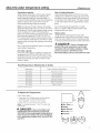
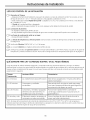
Installation Instructions
LOCATION (CONT.)
Catch Pan Installation
/
Routeto opendrain.Line
shouldbeat least3/4'"
(1.gcm)IDandpitched
for properdrainage.
A--Diameter ofwater heater
plus2" (5.1cm)min.
B--Maximum 2" (5.1cm)
NOTE:Auxiliarycatch pan lUST conformto localcodes.
CatchPanKitsare availablefrom the storewherethewater
heaterwas purchased,a builderstoreor any waterheater
distributor.
Required clearances:
Theremust bea 7"(17.5cm)clearancebetweenany object
and the Frontand Rearcoversinthe event serviceisneeded.
A minimumof 7" (17.5cm)clearancewith thesidesof the
water heaterisalsorecommendedfor serviceaccess.
X'
(17.5cm)
A 6"(152.4cm)minimumclearanceisrequiredto removethe
filter for cleaning.Thehot and coldwater plumbingand
electricalconnectionsmust notinterferewith the removalof
the filter.
.... .......... I 6"(152.4cm)
Condensotion droin
Theunit hasa condensatedrain;therefore adrain must be
availablein closeproximityto the unit.Thedrain must beno
higherthan 36"(91.4cm)abovethefloor (drainmust meet
state and localcodes).
If nodrain isavailable,then a commoncondensatepumpwith
a capacityno lessthan 1 gallon (3.8L)/daymustbe purchased
from a localbuilder supplystoreand installed.
MATERIALS NEEDED FOR INSTALLATION
1/2" Rigid PVC
droin pipe
(os required)
1/2"MNPTPVC
Connector
V2"PVC Tee Wire nuts
O
PVCGlue
THERMAL EXPANSION
Determine if o check volve exists in the inlet woter
line. It may have been installed in the cold water line as
a separate backflow preventer, or it may be part of a
pressure-reducing valve, water meter or water softener.
A check valve located in the cold water inlet line can
cause what isreferred to as a "closed woter system."
A cold water inlet line with no check valve or backflow
prevention device is referred to as an "open" water
system.
Aswater isheated, it expands in volume and creates
an increase in the pressure within the water system.
This action is referred to as "thermol exponsion." Inan
"open" water system, expanding water which exceeds the
capacity of the water heater flows back into the city main
where the pressure is easily dissipated.
A "closed woter system," however, prevents the
expanding water from flowing back into the main
supply line, and the result of "thermol exponsion" can
create a rapid and dangerous pressure increase in the
water heater and system piping. This rapid pressure
increase can quickly reach the safety setting of the relief
valve, causing it to operate during each heating cycle.
Thermal expansion, and the resulting rapid and repeated
expansion and contraction of components in the water
heater and piping system, can cause premature failure of
the relief valve, and possibly the heater itself. Replacing
the relief valve will not correct the problem!
Thesuggested method of controlling thermal expansion
isto install an expansion tank in the cold water line
between the water heater and the check valve (refer
to the illustration on page 15).The expansion tank is
designed with an air cushion built in that compresses
as the system pressure increases, thereby relieving the
over-pressure condition and eliminating the repeated
operation of the relief valve. Other methods of controlling
thermal expansion are also available. Contact your
installing contractor, water supplier or plumbing inspector
for additional information regarding this subject.
14

Installation Instructions
WATER SUPPLY CONNECTIONS
Refertothe illustrationbelowfor suggestedtypical installation.
Theinstallationofunionsor flexiblecopperconnectors is
recommendedon the hot andcoldwater connectionssothat
the water heatermay be easilydisconnectedfor servicingif
necessary.TheHOTand COLDwater connectionsare clearly
marked andare 3/4" NPTonall models.
NOTE: Install a shut-off valve in the cold water line near the
water heater. This will enable easier service or maintenance
of the unit later.
IMPORTANT: Do not apply heat to the HOT or COLD water
connections. If sweat connections are used, sweat tubing
to adapter before fitting the adapter to the cold water
connections on heater. Any heat applied to the hot or cold
water connection will permanently damage the internal
plastic lining in these ports.
TYPICAL INSTALLATION
Electricaljunction box(use
Toelectrical-_ onlycopperconductors)
To cold
distribution panel Union --ater
/w
supply
Union--..t_
Shut-offvalve
Hotwater
outletto fixtures
Jacket access panel -_
Jacket access
6" ( 15.2cm)
/
Drainvalve airgap
\
Thermal expansion
tank (if required)
3eratureand
pressure-reliefvalve
(shownin different
locationfor clarity)
valve
dischargelineto
suitableopendrain
CONDENSATION DRAIN TUBES
Thisunit hasa condensationtray. Thewater collectedinthe
tray drainsout of the sideofthe unit. It isimportant to installa
drain pipeto the primarydrain port coming off the sideofthe
unit Plumbone end tothe lowerdrain port on the sideof the
unit. Plumbthe otherend to adrain inthe flooror no higher
than :3'(0.9m)abovethefloor. Ifsuch drain isunavailable,
a condensatedrain pump (not
provided)must be purchasedand
installed.Thedrain pipeshouldbe
routed sothat the dischargewater
cannot contact liveelectricalparts
or personsandto eliminate potential
water damage.
RELIEF VALVE
A WARNING: Risko u,,itoo og -The
pressure rating of the relief valve must not exceed 150
PSI(1.03kPa),the maximum working pressure of the
water heater as marked on the rating plate.
A new combination temperature and pressure-relief
valve,complying with the Standardfor ReliefValves and
Automatic GasShut-Off Devicesfor Hot Water Supply
Systems,ANSIZ21.22,issupplied and must remain installed
in the opening provided and marked for the purpose on
the water heater. Novalve of any type should be installed
between the reliefvalve and the tank. Localcodes shall
govern the installation of reliefvalves.
TheBTUHrating ofthe reliefvalve must not be lessthan the
input rating ofthe water heater as indicated on the rating
label located on the front ofthe heater (1 watt=3.412 BTUH).
Connect the outlet of the reliefvalve to a suitable open drain
sothat the discharge water cannot contact liveelectrical
parts or persons and to eliminate potential water damage.
Pipingusedshould be of atype approved for hot water
distribution. The dischargeline must be no smallerthan the
outlet of the valve and must pitch downward from the valve
to allow complete drainage (bygravity)of the reliefvalve
and discharge line.Theend of the discharge line should
not be threaded or concealed and should be protected
from freezing. Novalve of anytype, restriction or reducer
coupling should be installed in the discharge line.
A CAUTION:
To reduce the risk of excessive pressures and
temperatures in this water heater, install temperature
and pressure protective equipment required by local
codes and no lessthan a combination temperature and
pressure relief valve certified by a nationally recognized
testing laboratory that maintains periodic inspection of
production of listed equipment or materials, as meeting
the requirements for ReliefValves and Automatic Gas
Shutoff Devices for Hot Water Supply Systems, ANSI
Z21.22.This valve must be marked with a maximum set
pressure not to exceed the marked maximum working
pressure of the water heater. Install the valve into an
opening provided and marked for this purpose in the
water heater, and orient it or provide tubing so that
any discharge from the valve exits only within 6 inches
above, or at any distance below, the structural floor, and
does not contact any live electrical part. The discharge
opening must not be blocked or reduced in size under
any circumstances.
15

Installation Instructions
TO FILL THE WATER HEATER
A WARNING: RiskofUnitDamage- The
tank must be full ofwater before heater is turned on.The
water heater warranty does not cover damage or failure
resulting from operation with an empty or partially
empty tank.
Hake certain the drain valve is completely closed.
Open the shut-off valve in the cold water supply line.
Open each hot water faucet slowly to allow the air to
vent from the water heater and piping.
A steady flow of water from the hot water faucet(s)
indicates a full water heater.
Fll" fault code during installation: If the unit is
powered on without a full tank, the error code "Fll" will
show in the display. Turn off the power, fill the tank with
water (seeabove), then turn the power back on.
NOTICE:
Do not mis-wire electrical connections. 240V AC or 208AC
must be applied across L1 and L2 wires as shown in
'Water heater junction box' illustration. Failure to do so
will VOID the warranty, and can result in 120V applied to
water heater, which may damage the compressor or other
electrical components.
If 4-conductor wire is supplied to the water heater, cap the
neutral, and connect the remaining wires as illustrated.
NOTEREGARDINGUTILITYPOWER-MANAGEMENTDEVICES
(Sometimes called PeakLoad Reduction Switches):
Some power-management switching devices or even some
basic timer switches exist that REDUCEvoltage from 240V
to 120V during high-electricity-demand periods. These
devices must be removed from the circuit providing power
to the water heater because of the potential unit damage
noted above.
However, switching devices which cut power from 240V to
0V on a periodic basis are acceptable.
"bAd linE" fault code during installation: If "bAd linE" is
shown on the display, the unit is not receiving the correct
voltage as a result of incorrect wiring. To correct this fault,
turn the power off to the unit, correct the wiring issue,then
turn the power back on.
ELECTRICAL CONNECTIONS
A separatebranchcircuitwith copperconductors,overcurrent
protectivedeviceand suitabledisconnecting meansmust be
providedbya qualifiedelectrician.
Allwiring must conformto localcodesor latesteditionof
NotionalElectricalCodeANSI/NFPA70.
Thewater heater iscompletely wiredto thejunction boxat the
top of thewater heater.An openingfor 1/2"electricalfitting is
providedfor fieldwiring connections.
Thevoltage requirementsand wattage loadfor the water
heaterare specifiedonthe ratinglabel onthe front ofthe
water heater.
The branch circuit wiring should include either:
1. Metallic conduit or metallic sheathed cable approved
for use as a grounding conductor and installed with
fittings approved for the purpose.
2. Nonmetallic sheathed cable, metallic conduit or
metallic sheathed cable not approved for use as a
ground conductor shall include a separate conductor
for grounding. It should be attached to the ground
terminals of the water heater and the electrical
distribution box.
To connect power to the water heater:
1. Turn the power off.
2. Remove the screw/screws holding the junction box
top cover.
3. Install L1to L1, L2 to L2 and ground to the green
ground wire connected to the bottom of the junction
box.
NOTE: Install electric connections according to local
codes or latest edition of National Electrical Code ANSI/
NFPA70.
Water heaterjunction box
HouseGround
A WARNING:Proper ground connection is
essential. The presence of water in the piping and water
heater does not provide sufficient conduction for a
ground. Nonmetallic piping, dielectric unions, flexible
connectors, etc., can cause the water heater to be
electrically isolated. Do not disconnect factory ground.
16

Installation Instructions
The manufacturer's warranty does not cover any
damage or defect caused by installation, attachment
or use of any type of energy-saving or other
unapproved devices (other than those authorized by the
manufacturer) into, onto or in conjunction with the water
heater. The use of unauthorized energy-saving devices
may shorten the life of the water heater and may
endanger life and property.
The manufacturer disclaims any responsibility for
such loss or injury resulting from the use of such
unauthorized devices.
If local codes require external application of insulation
blanket kits, the manufacturer's instructions included
with the kit must be carefully followed.
Application of any external insulation, blankets or
water pipe insulation to this water heater will require
careful attention to the following:
• Do not cover the temperature and pressure-relief
valve.
• Do not cover access panels to the heating elements.
• Do not cover the electrical junction box of the
water heater.
• Do not cover the operating or warning labels attached
to the water heater or attempt to relocate them on
the exterior of the insulation blanket.
• Do not block the air inlet/outlets in the top covers or
rear of the unit.
•][ypicalvertical
p_pmgarrangement
Typicalhorizontalpiping
arrangement
NOTE:This guide recommends minimum branch
circuit sizing based on the National Electric Code.
Refer to wiring diagrams in this manual for field wiring
connections.
BRANCH CIRCUIT SIZING GUIDE
J TOtalWaterHeater Wattage
3,000
4,000
4,500
5,000
5,500
6,000
8,000
9,000
10,000
ii,000
12,000
Recommended over_curren _Protection
(fuse or c rcu t breaker amperage rat ng}
208V 240V 277V 480V
20 20 15 15
25 25 20 15
30 25 25 IS
30 30 25 15
35 30 25 15
40 55 30 20
50 45 40 25
- 50 45 25
- 50 30
- 50 30
- - 35
J TotalwaterHeater Wattage
3,000
4,000
4,500
5,000
5,500
6,000
8,000
9,000
i0,000
11,000
12,000
copper wire size AWG Based
on N.E.C.Tab e310.16 (1670F/75aC.)
208V 240V 277V 480V
12 12 14 14
i0 i0 12 14
10 10 10 14
i0 i0 i0 14
8 i0 i0 14
8 8 10 12
8 8 8 10
8 8 10
8 10
8 10
- 8
17

Installation Instructions
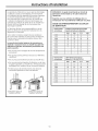
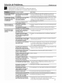
INSTALLATION CHECKLIST
[] 1.Tank location:
- Does room size require Iouvered door or similar ventilation? 10' x 10' x 7' (700 cu. ft.) or 240 square inches (0.15 m2)
air-flow urea needed.
- Buck of unit away from wall by 7 inches (17.5 cm),and sides have at least 7 inches (17.5 cm) clearance.
- Front of unit isfree and clear.
- Is the water heater level? If no, add shims under the base of the unit.
[] 2. Plumbing connections:
- Does not prevent air filter removal.
- No leaks after filling the tank with water, either when water is flowing or not.
[] 3. Condensate lines are in place:
- Main Drain Installed
[] 4. Temperature and pressure-relief valve is working and drain line completed per local code.
[] 5. Electrical verify 208/2/40 VACto L1 and L2at tank.
[] 6. Electrical connection does not prevent air filter removal.
[] 7. Verify control panel displays 120°F (49°C)Hybrid mode. Assist user in how to adjust temperature and modes (see
"About the Water Temperature Setting" section on page 7).
WHAT TO EXPECT FOR "NORMAL STARTUP" IN HYBRID MODE
After the unit has been installed, with all electrical and water connections secure and checked, then the unit should be
filled with water (vent tank by opening a hot water faucet somewhere in home to allow tank to fully fill with water). Once
tank is full and power is energized, you may experience the following:
Elapsed Time HEWH Actions Comments
0 to 2 minutes Unit will go through self-check. This 2-minute off-time prevents compressor
damage.
2 to 10 minutes Compressor and fun turn on This 8-minute period is used to ensure the tank is
full of water (Dry-fire prevention algorithm).
10 to 30 minutes Compressor and fun turn off, heat- To quickly provide initial amount of hot water for
ing elements turn on for about 20 user (about 25 gallons/94.6 L)
minutes
30 minutes and Upper element turns off and Uses efficient heat pump for majority of heating
beyond compressor turns buck on
NOTE:The heat pump operating range is 45°F to 120°F (7°Cto/49°C). If the ambient temperature is outside of this range,
the heat pump will turn off and the electric elements will be used until the ambient temperature returns to within the
operating range.
18

Troubleshooting... GEAppliances.com
_ efore you call for service....
Save time and money! Review the chart below first and you
may not need to call for service.
Possible Causes Whet To Do
Water heater makes Afan is used to move air • Some amount of fan sound is normal. Ifyou hear an
sounds through the system, abnormal sound or the sound level seems unusually loud,
then contact service.
Water heater is Room is not vented • If the room is smaller than 10' x 10' x 7' (3m x 3m x 2.1m),
making the room properly or is too small, then it must hove a Iouvered door or other means to allow
cooler air exchange with surrounding rooms.
Heat is removed from the air • This is normal
to heat the water
Water dripping down Condensate drain is • Clear out any debris in the drain port on the unit.
the outside of the clogged.
heater.
Hot/Cold water connections • Tighten the inlet and outlet pipe connections.
are not tightened.
Not enough or no hot Water temperature may • SeeAbout the Water Temperature Setting section.
water be set too low.
Hot water usage pattern • Change to different mode
exceeds the capability of the
water heater in current mode
Water usage may hove • Wait for the water heater to recover offer an abnormal
exceeded the capacity demand
of the water heater.
Ambient temperature is • For the water heater to work properly, its location needs
too low to have a temperature of :32° to 150°F for Standard
Electric mode and 45° to I20°F for all other modes.
Cold water inlet temperature • This is normal. The colder inlet water takes longer to heat.
may be colder during the
winter months.
Leaking or open hot water • Make sure all faucets are closed.
faucets.
Long runs of exposed pipe, • Insulate piping.
or hot water piping on
outside wall.
Not enough clearance to • Hake sure unit is 7" away from the wall.
allow air to circulate for the
heater pump.
Room size is not appropriate ° If room size is lessthan 10' x 10' x 7' (700 cu. ft.), install
for water heater. Iouvered door or similar ventilation.
A fuse is blown or o circuit • Replace fuse or reset circuit breaker.
breaker tripped.
Electric service to your home • Contact the local electric utility.
may be interrupted.
Improper wiring. • Seethe Installation Instructions section.
Manual reset limit (TCO}. • Seethe Safety Control section, see page 4.
Water connections to unit ° Correct piping connections.
reversed.
Electric supply may be off. • Hake sure electric supply to water heater is correct
disconnect switch, if used, are in the ON position.
19

Troubleshooting...
Water istoo hot
Possible Causes What To Do
Water temperature is set • SeeAbout the W(]ter Temper(]ture Setting section.
too high.
A CAUTION: Foryours(]fety,0ONOT(]ttempt rep(]ir ofelectric(]lwiring, controls,
he(]ting elements or other s(]fety devices. Refer rep(]irs to qu(]lified service personnel.
Electronic control has foiled. • Coil for service.
Rumbling noise Water conditions in your • Remove (]nd cleon the he(]ting elements. This should only
home caused o buildup of be done by (] qulified service personnel.
scale or mineral deposits
on the heating elements.
Relief valve producing Pressure buildup caused • This ison un(]ccept(]ble condition (]nd must be corrected.
popping sound by thermal expansion Cont(]ct the w(]ter supplier or plumbing contr(]ctor on how
or draining to o closed system, to correct this. Do not plug the relief v(]lve outlet.
The heater is beeping
and the display says
F]]
The water heater has not
been filled with water before
powering up. Powering up the
heater without water will
damage the electric heaters.
The water heater warranty
does not cover damage or
failure resulting from operation
with on empty or partially
empty tank.
The filter light is on. The filter requires cleaning.
A cleon filter is necessary for
effective operation.
The heater is beeping There is on issue with the
and the screen says heat pump system.
"FA F8"
• Fill the t(]nk completely with w(]ter. Press ENTER to stop
the (]l(]rm (]nd then press POWER when the t(]nk h(]s been
filled.
The heater isbeePing There ison issue with the
and the screen flashes water heater that requires
an error code immediate attention.
The water heater is Unit is not receiving 240VAC
beeping and the screen as intend.
flashes, "bAd linE', ........
Hot Water has a rotten Certain water supplies with
egg or sulfur smell high sulfate content will react
with the anode rod that is
present in oil water heaters
for corrosion protection of
the tank.
unit is not making Ifunit is using electric
normal sounds resistanceelements, it will
not make fan or compressor
sounds.
2O
• Follow the instructions on how to remove (]nd cleon the
filter on p(]ge 12.
• The unit will (]utom(]tic(]lly switch to (]nother (]v(]il(]ble
mode to ensure you continue to hove hot w(]ter. Cont(]ct
service immedi(]tely (]nd give them the codes listed on the
displ(]y screen.
• The he(]ter m(]y switch to (]nother (]v(]il(]ble he(]ting mode.
Cont(]ct service immedi(]tely. To stop the beeping noise
(unless error code F2,Fll or bAd linE)press either the UPor
down (]rrow button (]nd the (]l(]rm will stop (]nd the displ(]y
will go b(]ck to norm(]l (settemper(]ture).
Turn off power to w(]ter he(]ter (gener(]lly(it the bre(]ker
p(]nel). Then re(]d "Electric(]l Connections" section of
Inst(]ll(]tion Instructions, seep(]ge 16. Then,cont(]ct the
inst(]ller to verify electric(]l input to the w(]ter he(]ter.
The odor con be reduced or elimin(]ted in most w(]ter
he(]ters by repl(]cing the (]node rod with less-(]ctive
m(]teri(]l rod. Insome c(]ses,on (]dded step of
chlorin(]ting the w(]ter he(]ter (]nd (]11hot w(]ter lines m(]y
be necess(]ry,cont(]ct your Ioc(]lw(]ter profession(]l or
plumber for options (]nd instructions. CoilGE(it
1.888.4GEHEWH(1.888.443.4394)to le(]rn how to purch(]se
this repl(]cement (]node rod. A qu(]lified servicer or
plumber should do this repl(]cement. Use of (] non-GE
(]pproved (]node rod, or oper(]ting the w(]ter he(]ter
without (]GE(]pproved (]node rod will VOIDthe w(]rr(]nty.
• Check mode of unit.
For Service, please call 1.888.4GE.HEWH (1.888.443.4394)
Page is loading ...
Page is loading ...
Page is loading ...
Page is loading ...
Page is loading ...
Page is loading ...
Page is loading ...
Page is loading ...
Page is loading ...
Page is loading ...
Page is loading ...
Page is loading ...
Page is loading ...
Page is loading ...
Page is loading ...
Page is loading ...
Page is loading ...
Page is loading ...
Page is loading ...
Page is loading ...
Page is loading ...
Page is loading ...
Page is loading ...
Page is loading ...
Page is loading ...
Page is loading ...
Page is loading ...
Page is loading ...
Page is loading ...
Page is loading ...
Page is loading ...
Page is loading ...
Page is loading ...
Page is loading ...
Page is loading ...
Page is loading ...
Page is loading ...
Page is loading ...
Page is loading ...
Page is loading ...
Page is loading ...
Page is loading ...
Page is loading ...
Page is loading ...
Page is loading ...
Page is loading ...
Page is loading ...
Page is loading ...
Page is loading ...
Page is loading ...
Page is loading ...
Page is loading ...
-
 1
1
-
 2
2
-
 3
3
-
 4
4
-
 5
5
-
 6
6
-
 7
7
-
 8
8
-
 9
9
-
 10
10
-
 11
11
-
 12
12
-
 13
13
-
 14
14
-
 15
15
-
 16
16
-
 17
17
-
 18
18
-
 19
19
-
 20
20
-
 21
21
-
 22
22
-
 23
23
-
 24
24
-
 25
25
-
 26
26
-
 27
27
-
 28
28
-
 29
29
-
 30
30
-
 31
31
-
 32
32
-
 33
33
-
 34
34
-
 35
35
-
 36
36
-
 37
37
-
 38
38
-
 39
39
-
 40
40
-
 41
41
-
 42
42
-
 43
43
-
 44
44
-
 45
45
-
 46
46
-
 47
47
-
 48
48
-
 49
49
-
 50
50
-
 51
51
-
 52
52
-
 53
53
-
 54
54
-
 55
55
-
 56
56
-
 57
57
-
 58
58
-
 59
59
-
 60
60
-
 61
61
-
 62
62
-
 63
63
-
 64
64
-
 65
65
-
 66
66
-
 67
67
-
 68
68
-
 69
69
-
 70
70
-
 71
71
-
 72
72


GE GEH50DEEDSRA Owner's manual
- Category
- Water heaters & boilers
- Type
- Owner's manual
- This manual is also suitable for
Ask a question and I''ll find the answer in the document
Finding information in a document is now easier with AI
in other languages
Related papers
-
GE GEH50DEEDSRB Owner's manual
-
GE RE2H50R6-1NCWW Owner's manual
-
-
-
-
-
-
-
-
GE GE40S10BMM Reference guide
Other documents
-
Rheem Professional Classic Series: Standard Electric User manual
-
Bradford White RE2H80T10 User manual
-
A.O. Smith 9241333023 Installation guide
-
Bradford White E32-50S-3 Installation guide
-
-
Hotpoint RGB526DET3WW Installation guide
-
A.O. Smith ECS User manual
-
Hotpoint RGB508PET2WH Installation guide
-
Rheem XE65T10HD22U0 User manual
-
 Kenmore Elite 153592600 Owner's manual
