Page is loading ...

ferent wall materials
Failure to detach this restraint before moving furniture may result in injury or damage.
DO NOT ALLOW CHILDREN TO CLIMB ON FURNITURE
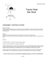
ASSEMBLY INSTRUCTIONS
Before You Begin:
Please identify all component parts and hardware pieces required before you begin. Carefully remove all of the
components from the packaging and set aside for assembly. Assemble on a soft surface to prevent scratching
during assembly.
Caution:
Tighten all components securely before use. Failure to do so may result in personal injury.
DO NOT use any sharp objects to open plastic wrapped components as damage to product or components
may result.
Warning:
CHOKING HAZARD - Small Parts. Adult Assembly Required.
Injury may result from tipping furniture. You must install the Tipping Restraint Hardware with the unit to prevent
the unit from tipping and causing any accidental injury, instability, death or damage. The tipping restraint is
intended only as a safety measure, it is not a substitute for proper adult supervision.
This tipping restraint is not an earthquake restraint. If you wish to add the extra security of earthquake
restraints, they must be purchased and installed separately.
Serious or fatal crushing injuries can occur from furniture tipping over. To prevent furniture from tipping over it
Customer Service email: CustomerExperience@theubiquegroup.com | Phone: 866-552-2810
LF-134-A-GG / LF-134-A-WH-GG / LF-134-A-GY-GG
Task Office Chair
Thank you for your purchase!


EVERY UBIQUE GROUP PRODUCT
�
Read this manual before using this product. Failure to follow the instructions
and safety precautions in this manual can result in serious injury or death.
Keep this manual in a safe location for future reference.

STEP 1
PARTS
5
1
1
2
1
1
1
1
1
A
B
C
D
E
F
G
H
I
1
1
1
3
4
J
K
L
M
N
8
6
1
1
O
P
Q
R
M7*110MM
M5*10MM
M6*25MM
M6*18MM
M6*14*1MM
M6*30MM
M4
M5
M6*18*1MM
I
H
KQ
J
R
Make sure the orientation of the back is exactly the
same as illustration. You can tell from the hole
patterns
and only threaded on
the inside.
the shortest screw.
J K R
Q
M7*110MM
x1 x1 x1 x1
M5*10MM M4
M5
Base
Backrest
1
Backrest
Align Back and Seat Connector (Part H)
with the holes on the Backrest (Part I).
Insert (1) M7*110MM Bolt (Part J) into the
left side hole then insert (1) M5*10MM
Screw (Part K) into the right side hole and
thread into Bolt J. Tighten using the Small
Allen Wrench (Part Q) and Large Allen
Wrench (Part R).

STEP 4
STEP 3
STEP 2
F
H
I
L
O
F
G
P
O
Note: Make sure the armrest is in the correct direction
R
x1
M5
L
x2
M6*25MM
O
x2
M6*14*1MM
R
x1
M5
P
x6
M6*30MM
O
x6
M6*14*1MM
R
x1
M5
L
x1
M6*25MM
N
x1
M6*18*1MM
L
N
E
H
FRONT
FRONT
Arms
Washer
Seat Front
underside of Seat (Part F) using (6)
using Large Allen Wrench (Part R).
Attach the other end of the Back and
Seat Connector (Part H) to the
underside of the seat using (2)
M6*25MM Screws (Part L) and (2)
(Part O).
Tighten using Large Allen Wrench
(Part R).
M6*25MM Screw
*1MM
Washer
Back and Seat Connector
Backrest
M6*25MM Screw
M6*18*1MM
Washer
Control Mechanism
Back and Seat
Connector
extender portion of the Back and Seat
Connector (Part H) into the slot in the back of the
Control Mechanism (Part E). Attach using (1) M6*25MM
Screw (Part L) and (1) M6*18*1MM Washer (Part N).
Tighten using Large Allen Wrench (Part R).
Seat Front
Right Arm
NOTE: For safety
ensure washers
are used.
NOTE: For safety
ensure washers
are used.
NOTE: For safety
ensure washers
are used.

STEP 6
STEP5
A
B
C
D
EF
HG
I
F
E
M
FRONT
FRONT
R
x1
M5
M
x4
M6*18MM
Secure Control Mechanism (Part E) to the underside of
the Seat (Part F) using (4) M6*18MM Screws (Part M).
Tighten using Large Allen Wrench (Part R).
M6*18MM Screw
Control Mechanism
Seat (underside view)
6A: Insert (5) Casters (Part A) into the
Base (Part B).
6B: Insert Gas Lift Cylinder (Part C)
into Base (Part B) then slide the
Cylinder Cover (Part D) over it.
6C: Align the hole in the Control
Mechanism (Part E) on the underside
of the assembled Seat with the top of
the Gas Lift Cylinder (Part C) and
push down firmly until fully seated.
Backrest
Arms
Seat
Control
Mechanism
Cylinder Cover
Gas Lift Cylinder
Base
Casters
Back and Seat Connector
/