Reliable 4200SW User manual
- Category
- Sewing machines
- Type
- User manual
This manual is also suitable for
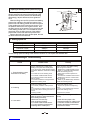
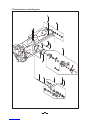
Reliable 4200SW is a versatile industrial sewing machine designed for heavy-duty applications. With its robust construction and advanced features, this machine offers efficient and precise sewing capabilities for a wide range of materials.
The 4200SW is equipped with a powerful 370W motor that delivers a maximum sewing speed of 2500 rpm, ensuring fast and efficient operation. The maximum stitch length of 9mm allows for flexible stitching options, while the adjustable thread tension and stitch length settings provide precise control over the sewing process.
The machine's horizontal rotating hook and synchronized driving system contribute to smooth feeding and consistent stitch quality. The auto-lubrication system ensures optimal performance and longevity, while the adjustable presser foot pressure and height provide versatility for different fabric thicknesses.


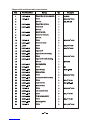
-
 1
1
-
 2
2
-
 3
3
-
 4
4
-
 5
5
-
 6
6
-
 7
7
-
 8
8
-
 9
9
-
 10
10
-
 11
11
-
 12
12
-
 13
13
-
 14
14
-
 15
15
-
 16
16
-
 17
17
-
 18
18
-
 19
19
-
 20
20
-
 21
21
-
 22
22
-
 23
23
-
 24
24
-
 25
25
-
 26
26
-
 27
27
-
 28
28
-
 29
29
-
 30
30


Reliable 4200SW User manual
- Category
- Sewing machines
- Type
- User manual
- This manual is also suitable for
Reliable 4200SW is a versatile industrial sewing machine designed for heavy-duty applications. With its robust construction and advanced features, this machine offers efficient and precise sewing capabilities for a wide range of materials.
The 4200SW is equipped with a powerful 370W motor that delivers a maximum sewing speed of 2500 rpm, ensuring fast and efficient operation. The maximum stitch length of 9mm allows for flexible stitching options, while the adjustable thread tension and stitch length settings provide precise control over the sewing process.
The machine's horizontal rotating hook and synchronized driving system contribute to smooth feeding and consistent stitch quality. The auto-lubrication system ensures optimal performance and longevity, while the adjustable presser foot pressure and height provide versatility for different fabric thicknesses.
Ask a question and I''ll find the answer in the document
Finding information in a document is now easier with AI


