Page is loading ...

77-3139-R7 (12/2022) 1 / 14 www.carlisleft.com
31-451
31-424
31-454
EN
SERVICE MANUAL
15:1 GEAR & DIRECT DRIVEN AIR MOTOR
DRIVES AND AGITATOR ASSEMBLIES
FOR OPEN AND CLOSED DRUMS AND LARGE TANK ASSEMBLIES
31-526

EN
77-3139-R7 (12/2022)2 / 14www.carlisleft.com
LOCK OUT / TAG-OUT
Failure to de-energize, disconnect, lock out and tag-out all power
sources before performing equipment maintenance could cause
serious injury or death.
OPERATOR TRAINING
All personnel must be trained before operating finishing
equipment.
EQUIPMENT MISUSE HAZARD
Equipment misuse can cause the equipment to rupture,
malfunction, or start unexpectedly and result in serious injury.
PROJECTILE HAZARD
You may be injured by venting liquids or gases that are released
under pressure, or flying debris.
PINCH POINT HAZARD
Moving parts can crush and cut. Pinch points are basically any
areas where there are moving parts.
INSPECT THE EQUIPMENT DAILY
Inspect the equipment for worn or broken parts on a daily basis.
Do not operate the equipment if you are uncertain about its
condition.
In this part sheet, the words WARNING, CAUTION and NOTE are used to
emphasize important safety information as follows:
Hazards or unsafe practices which
could result in minor personal injury,
product or property damage.
!
CAUTION
Hazards or unsafe practices which
could result in severe personal
injury, death or substantial property
damage.
!
WARNING
Important installation, operation or
maintenance information.
NOTE
Read the following warnings before using this equipment.
READ THE MANUAL
Before operating finishing equipment, read and understand all
safety, operation and maintenance information provided in the
operation manual.
WEAR SAFETY GLASSES
Failure to wear safety glasses with side shields could result in
serious eye injury or blindness.
NEVER MODIFY THE EQUIPMENT
Do not modify the equipment unless the manufacturer provides
written approval.
IT IS THE RESPONSIBILITY OF THE EMPLOYER TO PROVIDE THIS INFORMATION TO THE OPERATOR OF THE EQUIPMENT.
FOR FURTHER SAFETY INFORMATION REGARDING THIS EQUIPMENT, SEE THE GENERAL EQUIPMENT SAFETY BOOKLET (77-5300).
KNOW WHERE AND HOW TO SHUT OFF THE EQUIPMENT
IN CASE OF AN EMERGENCY
PRESSURE RELIEF PROCEDURE
Always follow the pressure relief procedure in the equipment
instruction manual.
NOISE HAZARD
You may be injured by loud noise. Hearing protection may be
required when using this equipment.
STATIC CHARGE
Fluid may develop a static charge that must be dissipated through
proper grounding of the equipment, objects to be sprayed and all
other electrically conductive objects in the dispensing area. Improper
grounding or sparks can cause a hazardous condition and result in
fire, explosion or electric shock and other serious injury.
WEAR RESPIRATOR
Toxic fumes can cause serious injury or death if inhaled.
Wear a respirator as recommended by the fluid and solvent
manufacturer’s Safety Data Sheet.
TOXIC FLUID & FUMES
Hazardous fluid or toxic fumes can cause serious injury or death if
splashed in the eyes or on the skin, inhaled, injected or
swallowed. LEARN and KNOW the specific hazards or the fluids
you are using.
KEEP EQUIPMENT GUARDS IN PLACE
Do not operate the equipment if the safety devices have been
removed.
!
WARNING
AUTOMATIC EQUIPMENT
Automatic equipment may start suddenly without warning.
FIRE AND EXPLOSION HAZARD
Improper equipment grounding, poor ventilation, open flame or
sparks can cause a hazardous condition and result in fire or
explosion and serious injury.
MEDICAL ALERT
Any injury caused by high pressure liquid can be serious. If you
are injured or even suspect an injury:
• Go to an emergency room immediately.
• Tell the doctor you suspect an injection injury.
• Show the doctor this medical information or the medical alert
card provided with your airless spray equipment.
• Tell the doctor what kind of fluid you were spraying or
dispensing.
GET IMMEDIATE MEDICAL ATTENTION
To prevent contact with the fluid, please note the following:
• Never point the gun/valve at anyone or any part of the body.
• Never put hand or fingers over the spray tip.
• Never attempt to stop or deflect fluid leaks with your hand,
body, glove or rag.
• Always have the tip guard on the spray gun before spraying.
• Always ensure that the gun trigger safety operates before
spraying.

EN
77-3139-R7 (12/2022) 3 / 14 www.carlisleft.com
15:1 GEAR DRIVEN AGITATORS FOR 55 GALLON DRUMS WITH EXISTING AGITATOR:
31-451 55 Gallon Agitator Drive with threaded adapter for drums with existing agitator
Before attempting any installation of agitators onto
pressure feed tanks, the tanks must be relieved of
pressure as high pressure can cause a serious injury.
Pressure is maintained in a pressure tank after the
system has been shut down. Before attempting
removal of cover, fill cap, or center plug, pressure
must be relieved using the following steps:
!
WARNING
PRESSURE RELIEF PROCEDURE
(IF USED ON PRESSURIZED TANKS)
1. Turn off the main air supply to the tank.
2. Close air inlet valve located on tank air manifold. Remove
air inlet hose.
3. Bleed off air in the tank by turning the air relief valve
thumb screw counter-clockwise. Wait until all the air has
escaped through the valve before removing the pressure
tank cover, fill cap, or center plug.
4. Leave the air relief valve open until you have reinstalled the
cover, fill cap, or center plug.
AIR SUPPLY
Air supplies (compressors etc.) shall be sited in a non-
hazardous area with a filter on the air intake system to
prevent the ingress of dust or similar foreign materials into the
parts where compression takes place.
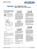
OPTIONAL AIR MOTOR LUBRICATION
(Lubrication will extend the life of the motor)
An automatic air line filter/lubricator should be installed in the
air supply line no more than 18” from the air motor. A 5
micron filter is recommended. Install the lubricator level with
or above the motor so the oil mist will blow directly into or
down into the motor (see Fig. 1).
Fill the oil reservoir with SAE 10W motor oil.
Adjust lubricator
to feed 1 drop of
oil for every 50
cfm of air or 1
drop per minute
of continuous
running.
The unit may also
be lubricated
manually by adding 10-20 drops of oil SAE 10 weight oil into
the air inlet fitting at the start of each shift.
Periodically—Remove air adjusting valve and air strainer and
flush motor with a clean suitable solvent. Remove trapped
particles from screen and clean air strainer felt.
Fig 1 MAIN AIR LINE
MUFFLER
AIR MOTOR
FILTER
REGULATOR
LUBRICATOR
ISOLATOR
VALVE
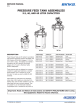
DESCRIPTIONS
5:1 GEAR AND DIRECT DRIVE AGITATORS FOR 55 GALLON OPEN TOP DRUMS:
31-526 55 Gallon Direct Drive Agitator with Stainless Steel drum cover
31-527 55 Gallon Direct Drive Agitator with Plated Steel drum cover
31-424 55 Gallon Agitator with Stainless Steel Drum Cover
31-397 55 Gallon Agitator with Plated Steel Drum Cover
31-525 Direct Drive Agitator assembly (Less Cover)
31-400 Gear Driven Agitator Assembly (less cover)
31-524 Direct Drive (to suit 31-525, with hose and fittings)
31-456 Agitator Drive for 31-423, 31-397, and 31-400
41-3305 Agitator only (less drive and less cover)
31-523 Direct Drive to suit 30 & 60 Gallon pressure Tanks (less hose and fittings)
31-455 Agitator Drive for 30 and 60 Gallon Tanks (Includes 13” air hose and fittings)
15:1 GEAR DRIVEN AGITATORS FOR 55 GALLON DRUMS WITH EXISTING AGITATOR:
31-454 55 Gallon Agitator Drive with bracket hardware for drums with existing agitator
31-453 Replacement Drive for 31-394
31-451
31-424
31-454
31-451
31-424
31-454

EN
77-3139-R7 (12/2022)4 / 14www.carlisleft.com
55 GALLON AGITATORS WITH DIRECT & 15:1 GEAR REDUCED DRIVES FOR OPEN TOP DRUMS
83-2114 STUFFING BOX ASSEMBLY
(Item 4)
55 GALLON AGITATORS
31-527 Direct drive agitator, plated steel cover
31-397 15:1 gear driven agitator, plated steel cover
31-526 Direct drive agitator, Stainless steel cover
31-424 15:1 gear driven agitator, Stainless steel cover
31-525 Direct drive agitator (no cover)
31-400 15:1 gear driven agitator (no cover)
41-3305 (no drive or cover) (items 3-11)

EN
77-3139-R7 (12/2022) 5 / 14 www.carlisleft.com
15:1 AGITATOR DRIVE
31-455 with Air Hose/ttings (shown)
31-456 less Air Hose/tting
55 GALLON AGITATOR, DIRECT AND 15:1
AGITATOR DRIVE PARTS LIST
Ref.
No.
Replacement
Part No. Description
Ind.
Parts
Req'd.
1
31-452 15:1 AGITATOR DRIVE
(INCLUDED WITH 31-397, 31-400, 31-424)
131-455 15:1 AGITATOR DRIVE
(INCLUDES ITEMS 37, 38, 39)
31-524 DIRECT DRIVE
(INCLUDES ITEMS 37, 38, 39)
2A 31-124 PLATED STEEL COVER 1
2B 31-426 STAINLESS STEEL COVER
3 41-3305 AGITATOR LESS DRIVE 1
4 83-2114 STUFFING BOX ASSEMBLY 1
5 41-172 LOCKNUT 1
6 83-2197 PADDLE ASSEMBLY, SS 2
7 20-2079 HEX NUT 5/16-18, SS 4
8 83-2194 PADDLE, SS 4
9 20-2077 HEX HD. CAP SCREW 5/16-18 X 1-1/2"
LG, SS 4
10 83-2132 BLOCK, SS 2
11 20-1741 SQ. HD. SET SCREW 3/8-16 X 1" LG, SS 2
12 83-2107 BEARING ASSEMBLY 1
13 83-2112 GLAND 1
14 83-2111-K4 PACKING SET
(INCL 4/EA 83-2111 PACKINGS) 1
15 83-2110 WASHER 1
16 83-1211 PIN 1
17 83-2099 SHAFT 1
18 83-2109 BOX ASSEMBLY 1
19 83-3032 BEARING (INCLUDED IN ITEM 18) 1
20 ----- BOX (INCLUDED IN ITEM 18) 1
21 20-1237 SOC. HD. SET SCREW 1/4-20 X 1/4" LG 1
22 31-434 GEAR-MOTOR 1
31-510 DIRECT DRIVE 1HP AIR MOTOR
23 QSK-071 MUFFLER (DUAL FELT) 1
24 --- STRAINER CAP 1
▲ 25 --- SCREEN 2
▲ 26 --- FELT 2
27 --- STRAINER BODY 1
28 H-2008 DM NIPPLE, 1/4 NPT X 1/4 NPS
(2/EA INCL WITH 31-396-1) 1 OR 2
29 HAV-500 AIR ADJUSTING VALVE 1
30 31-398 DRIVE SHAFT ASSEMBLY 1
31 31-57 COUPLING 1
32 Purchase
Locally SET SCREW 5/16-18 X 5/16" LONG 1
33 31-395 COUPLING ADAPTER 1
31-510 BDL MOUNT ASSEMBLY
34 Purchase
Locally HEX HD. CAP SCREW 3/8-16 X 1" LONG 2
35 Purchase
Locally LOCK WASHER 3/8" 2
36 Purchase
Locally HEX HD. CAP SCREW 3/8-16 X 2" LONG 1
37 HA-57011 HOSE ASSEMBLY 13" LONG, 1/4 NPS(F) SW
ENDS (INCLUDED WITH 31-396-1 ONLY) 1
38 20-1753-1 BUSHING, 1/4 NPT(F) X 3/8 NPT(M)
(INCLUDED WITH 31-396-1 ONLY) 1
▲ Order KK-5006 Strainer Screen and Felt Kit
5:1 GEAR REDUCTION FOR
OPEN TOP DRUMS
DIRECT AGITATOR DRIVE
31-523 less air hose/ttings
31-524 with air hose/ttings

EN
77-3139-R7 (12/2022)6 / 14www.carlisleft.com
55 GALLON AGITATOR AND
15:1 AGITATOR DRIVE OPERATION
Failure to properly lubricate the air motor will result in
premature motor failure and will void the warranty.
!
CAUTION
1. Lubricate air motor. Follow the lubrication instructions on page 3.
2. Open the valve to the main air line, and slowly open the air
adjusting valve (29) until the agitator turns.
3. Adjust speed of the agitator with the air adjustment valve (29). Do
not run unit at excessive speeds. Typical speeds are 50 to 70 RPM.
55 GALLON AGITATOR AND 15:1 AGITATOR
DRIVE INSTALLATION INSTRUCTIONS
Before attempting any installation of agitators onto
pressurized tanks, the tanks must be relieved of pressure
as high pressure can cause a serious injury. Pressure is
maintained in a pressure tank after the system has been shut
down. Before attempting removal of cover, fill cap, or center
plug, pressure must be relieved using the pressure relief
procedure on page 3.
!
WARNING
1. Insert the 83-2114 Stuffing Box Assembly (4) into the drum cover
as shown.
2. Align the pin in the stuffing box housing (18) with the notch in the
drum cover (2). See Figure 1 below.
3. Secure the Stuffing Box Assembly (4) to the cover (2) with the
Locknut (5). Make sure this connection is tight.
4. Attach each Paddle Assembly (6). Tighten securely. For two paddle
assemblies, locate on the highest and lowest flats. Orient paddle
assemblies as shown.
5. Place cover with stuffing box and paddles on drum.
6. Place the Agitator Drive (1) over the top of the shaft (17). Align the
pin (16) with the coupling (31).
7. Attach the Drive Unit (1) to the Stuffing Box (4) with the screws
(34) and lock-washers (35)provided. Tighten securely.
8. The Gear-motor (22) orientation may be adjusted by loosening the
cap screw (36) and rotating the unit to the desired position.
Re-tighten the screw (36) after the unit is positioned as desired.
9. The position of the air motor (80) can be adjusted by removing the
screws (84) and lockwashers (85) rotating the air motor in 90°
increments. Re-tighten the screws after desired orientation is
reached.
10. Connect air hose to the air adjustment valve (29).
Stufng Box Housing
Cover
Pin
Figure 1
AGITATOR DRIVE UNITS FOR
AGITATOR EQUIPPED DRUMS
31-451 AGITATOR DRIVE

EN
77-3139-R7 (12/2022) 7 / 14 www.carlisleft.com
ITEM
NO. PART NO. DESCRIPTION QTY.
40 QSK-071 MUFFLER & AIR STRAINER ASSEMBLY
(DUAL FELT) 1
41 STRAINER CAP 1
42 ▲SCREEN 2
43 ▲l FELT 2
44 STRAINER BODY 1
45 HAV-500 ADJUSTING VALVE 1
46 H-2008 ADAPTER, 1/4 NPSM X NPT
PLATED BRASS 1
47 31-434 AGITATOR DRIVE 1
48
Purchase Locally
HEX NUT, 3/8-16 1
49
Purchase Locally
LOCK WASHER 3/8" 1
ITEM
NO. PART NO. DESCRIPTION QTY.
50
Purchase Locally
HEX HD. CAP SCREW
3/8-16 X 2-1/2" LONG 1
51 QS-238 AIR MOTOR SUPPORT 1
52 QS-456 SCREW ASSSEMBLY 1
53 QS-455 DRIVE COUPLING ASSEMBLY 1
54
Purchase Locally
COTTER PIN, 1/16" X 1/2" 1
55 QS-237 DRIVER PIN 1
56 QS-457 ADAPTER 1
57 QS-240 DRIVER SHAFT, 1/2" SQUARE 1
57 QS-242 DRIVER SHAFT, 7/16" SQUARE 1
Parts are included within the following packing kits:
l KK-5001-1A AIR MOTOR REPAIR KIT
▲ KK-5006 STRAINER SCREEN AND FILTER KIT
31-453 DRIVE UNIT ASSEMBLY
FOR 31-454
31-451 DRIVE UNIT ASSEMBLY
ITEM
NO. PART NO. DESCRIPTION QTY.
40 QSK-071 MUFFLER & AIR STRAINER ASSEMBLY
(DUAL FELT) 1
41 STRAINER CAP 1
42 ▲SCREEN 2
43 ▲l FELT 2
44 STRAINER BODY 1
45 HAV-500 ADJUSTING VALVE 1
46 H-2008 ADAPTER, 1/4 NPSM X NPT
PLATED BRASS 1
60 31-434 DRIVE UNIT 1
61 31-398 DRIVE SHAFT ASSEMBLY 1
ITEM
NO. PART NO. DESCRIPTION QTY.
62
Purchase Locally
HEX HEAD CAP SCREW
3/8-16 X 2" LONG 1
63 31-395 COUPLING ADAPTER 1
64
Purchase Locally
HEX HEAD CAP SCREW
3/8-16 X 1" LONG 2
65
Purchase Locally
LOCK WASHER 3/8" 2
66
Purchase Locally
STREET ELBOW, 1/4" NPT M X F 1
67
Purchase Locally
PIPE, 1/4" NPT X 6" LONG 1
68
Purchase Locally
COUPLING, 1/4" NPT 1
Parts are included within the following packing kits:
l KK-5001-1A AIR MOTOR REPAIR KIT
▲ KK-5006 STRAINER SCREEN AND FILTER KIT
AGITATOR DRIVE UNITS FOR AGITATOR EQUIPPED DRUMS (CONTINUED)

EN
77-3139-R7 (12/2022)8 / 14www.carlisleft.com
AGITATOR DRIVE UNITS FOR AGITATOR EQUIPPED DRUMS
31-454 AGITATOR DRIVE ASSEMBLY
31-454 AGITATOR DRIVE ASSEMBLY
ITEM
NO. PART NO. DESCRIPTION QTY.
69 31-434 DRIVE UNIT 1
70 31-28 COUPLING ASSEMBLY 1
71
Purchase Locally
SET SCREW, 5/16 X 5/16" LONG, CUP POINT 2
72 83-1211 ROLL PIN 1
73 31-25 SHAFT 1
74 31-32 AIR MOTOR SUPPORT 2
75 31-31 CLAMP ASSEMBLY 1
76
Purchase Locally
SET SCREW, 5/16 X 3/8" LONG , CUP POINT 4
77 31-35 DRIVE BASE 1
78 31-33 BRACKET 1
79 31-21 COUPLING (7/16" SQUARE) 1
79 31-22 COUPLING (5/8" SQUARE) 1
79 31-23 COUPLING (1/2" SQUARE) 1
79 31-24 COUPLING (3/8" SLOTTED) 1
Parts are included within the following packing kits:
l KK-5001-1A AIR MOTOR REPAIR KIT
▲ KK-5006 STRAINER SCREEN AND FILTER KIT

EN
77-3139-R7 (12/2022) 9 / 14 www.carlisleft.com
31-453 & 31-454
1. Loosen cap screw (64) and separate the gear-motor (47)
from the coupling adapter (63).
2. Align the set screw detent on the drive shaft assembly (61)
with the set screw (71) in the coupling assembly (70) and
tighten the set screw securely
3. Re-attach the gear-motor (47) to the coupling adapter (79)
and tighten the cap screw (64).
4. Align holes on the coupling adapter (79) to the mounting
holes on the drive base (77). Secure tightly with screws
(62) and lock washers (65).
5. Connect the desired coupling (79) to the shaft (73) with
set screw (71).
6. Place entire assembly across drum and align the coupling
with the end of the pre-fitted agitator shaft.
7. After unit is positioned, clamp unit to drum.
8. The gear-motor orientation may be adjusted by loosening
the cap screw (64) and rotating the gear motor (47) to the
desired position and re-tightening the cap screw (64).
31-451
1. Adapter (56) has two thread sizes: 1-1/2” NPS (m) on one
end and 2” NPS(m) on the other end. Choose the proper
thread size and place the adapter over the agitator shaft of
the drum and screw down securely.
2. Select the proper driver shaft (57) and attach it to drive
coupling assembly (53) with driver pin (55) and cotter pins
(54). Place the assembly on the shaft of the drum agitator.
3. Slip air motor support (51) down over drive coupling
assembly (53) and adapter (56).
4. Tighten air motor support (51) securely with screw
assembly (52).
5. Install gear-motor (47) on the air motor support (51),
being sure to engage the shaft of the drive coupling
assembly (53).
6. Tighten cap screw (50) and hex nut (48).
7. Connect supply line to air adjusting valve (45).
8. The gear-motor orientation may be adjusted by loosening
the cap screw (64) and rotating the gear motor (47) to the
desired position and re-tightening the cap screw (64).
31-451
Failure to properly lubricate the air motor will result in
premature motor failure and will void the warranty.
!
CAUTION
1. Lubricate air motor. Follow the lubrication instructions on
page 3.
2. Open the valve to the main air line, and slowly open the
air adjusting valve (45) until the agitator turns.
3. Adjust speed of the agitator with the air adjustment
valve (45). Do not run unit at excessive speeds.
Typical speeds are 50 to 70 RPM.
31-523 & 31-524
Failure to properly lubricate the air motor will result in
premature motor failure and will void the warranty.
!
CAUTION
1. Lubricate air motor; see associated air motor manual (77-
3356) for instruction and frequency.
2. Open the valve to the main air line, and slowly open the air
adjusting valve (29) until the agitator turns.
3. Adjust speed of the agitator with the air adjustment valve
(29). Do not run unit at excessive speeds. Typical speeds
are 50 to 70 RPM. Note to prolong the life of the motor we
do not recommend running in excess of 300 RPM.
31-523 & 31-524
1. Align the air motor drive (coupling slot) with the stuffing
box pin (16) and place on to stuffing box assembly
83-2114.
2. Rotate air motor drive assembly to align fixing holes on the
stuffing box assembly 83-2114 and secure with fixings
provided.
3. Connect supply line to air adjusting valve.
INSTALLATION INSTRUCTIONS OPERATION
31-453 & 31-454
Failure to properly lubricate the air motor will result in
premature motor failure and will void the warranty.
!
CAUTION
1. Lubricate air motor. Follow the lubrication instructions on
page 3.
2. Open the valve to the main air line, and slowly open the
air adjusting valve (45) until the agitator turns.
3. Adjust speed of the agitator with the air adjustment
valve (45). Do not run unit at excessive speeds.
Typical speeds are 50 to 70 RPM.

EN
77-3139-R7 (12/2022)10 / 14www.carlisleft.com
31-434 15:1 GEAR REDUCTION DRIVE ASSEMBLY
31-437-K AIR MOTOR & COUPLING ASSEMBLY
BASE DRIVE UNIT
31-437-K PARTS LIST
ITEM
NO. PART NO. DESCRIPTION QTY.
40 QSK-071 MUFFLER & AIR STRAINER ASSEMBLY
(DUAL FELT) 1
41 STRAINER CAP 1
42 ▲SCREEN 2
43 ▲l FELT 2
44 STRAINER BODY 1
81 20-6990 COUPLING ASSEMBLY 1
87 QS-190 END CAP 1
88 lEND CAP GASKET 1
89 PT-58 BEARING 2
90
Purchase Locally
MACHINE SCREW, 1/4-28 X 1/2" 12
91 FRONT PLATE 1
92 PT-59-1-K10 lEND PLATE SPACER KIT 2
93 QS-189-1-K10 DOWEL PIN 4
94 BODY 1
95 lVANE 4
96 ROTOR ASSEMBLY 1
97 END PLATE 1
98 37-90 SEAL 1
31-434 PARTS LIST
ITEM
NO. PART NO. DESCRIPTION QTY.
80 31-437-K AIR MOTOR WITH COUPLING
(INCL W/ 31-434) 1
81 20-6990 COUPLING ASSEMBLY 1
82 20-1068 COUPLING SPIDER 1
83
Purchase Locally
SET SCREW, 1/4-20 X 5/16" 4
84 31-422 COVER PLATE (INCL W/ 31-435-K) 1
85
Purchase Locally
CAP HEAD SCREW, M6 X 10mm 2
86 31-435-K 15:1 REDUCER WITH COUPLING
(INCL W/ 31-434) 1
Parts are included within the following packing kits:
l KK-5001-1A AIR MOTOR REPAIR KIT
▲ KK-5006 STRAINER SCREEN AND FILTER KIT
31-434 GEAR REDUCTION DRIVE
80
81
82
83
86
85
84
81
77-3139
Page 9
41
40
42 43 42 44
87
88
89 90
92
93
91
94
95
96
97
89
90
93
92
98
31-437-K AIR MOTOR & COUPLING KIT

EN
77-3139-R7 (12/2022) 11 / 14 www.carlisleft.com
CONDITION CAUSE CORRECTION
Air motor sluggish or inefcient.
Air motor mufer (40) is clogged. Clean or replace the felt (43).
Replace mufer (40) if necessary.
Air motor needs lubrication or cleaning.
Lubricate (see "Air Motor Lubrication"
section). Disassemble and clean per parts
replacement instructions.
Motor vanes need replacing or
contaminants present in
motor chamber.
Disassemble, clean motor per parts
replacement instructions. Replace worn
vanes.
Air motor bearing (89) worn
.
Replace bearings per parts replacement
instructions
.
AIR MOTOR REBUILD
(SEE EXPLODED VIEW OF 31-437-K ON PAGE 9.)
Do not pry front plate (91) or end plate (97) from air motor
body (94) with a screwdriver. This will dent the surface of the
body and plates and causing leaks. A puller tool should be
used to remove the plate from the motor body while
maintaining the positions of the shaft.
Always install new spacers (92) when re-assembling air motor.
Assemble the end plates to the body using an arbor press with
a pusher acting on both races of the bearing while rigidly
supporting the opposite (drive) end of the shaft.
AIR MOTOR DRIVE SERVICE CHECKS
GEAR BOX OIL
The gearbox (86), page 9, contains a special high quality gear
oil, made specifically for worm drive gearboxes. The oil that
was installed at the factory should be sufficient for the life of
the gearbox. If oil should ever be required, drain the gearbox
completely. Then add 80mL [2.7 oz] of 31-439 gear oil.
Do not substitute another gear oil or it may result in damage
to your equipment.
!
WARNING

EN
77-3139-R7 (12/2022)12 / 14www.carlisleft.com
15:1 AGITATOR DRIVE FLEX COUPLING INSTALLATION
80
81
SET SCREW
1/8" HEX
86
81
82
SET SCREW
1/8" HEX
COUPLING JAW
COUPLING SPIDER
(82)
238mm
911
32
"
REF
83
83
81
SET SCREW
1/8" HEX
Assemble one coupling jaw from the coupling assembly (81) onto the air motor
shaft (80). Make sure to keep the coupling face ush with the end of the motor
shaft as shown. Apply Loctite 243 (or equivalent) to set screw threads. Align the
set screw to motor shaft at and tighten.
Assemble one coupling jaw to the gearbox shaft. Apply Loctite 243 (or equivalent)
to set screw threads. Align set screw to at and tighten the shaft should rotate
freely after the coupling jaw is installed.
After assembling the coupling jaws and spider as shown above, align the coupling
jaws of the air motor (80) to the spider and jaws of the gearbox coupling (86),
and insert the air motor into the coupling guard. Align the set screw holes on the
coupling guard to the drill points on the air motor hub. Orient the air motor as
required. Apply Loctite 243 (blue) to the four set screws (83) and tighten securely.

EN
77-3139-R7 (12/2022) 13 / 14 www.carlisleft.com
NOTES

EN
77-3139-R7 (12/2022)14 / 14www.carlisleft.com
WARRANTY POLICY
This product is covered by Carlisle Fluid Technologies’ materials and workmanship limited warranty.
The use of any parts or accessories, from a source other than Carlisle Fluid Technologies,
will void all warranties. Failure to reasonably follow any maintenance guidance provided
may invalidate any warranty.
For specic warranty information please contact Carlisle Fluid Technologies.
Carlisle Fluid Technologies is a global leader in innovative nishing technologies.
Carlisle Fluid Technologies reserves the right to modify equipment specications without prior notice.
BGK™, Binks®, DeVilbiss®, Hosco®, MS®, and Ransburg®
are all registered trademarks of Carlisle Fluid Technologies, LLC.
©2022 Carlisle Fluid Technologies, LLC.
All rights reserved.
For technical assistance or to locate an authorized distributor,
contact one of our international sales and customer support locations.
Region Industrial/Automotive Automotive Renishing
Americas Tel: 1-800-992-4657 Tel: 1-800-445-3988
Fax: 1-888-246-5732 Fax: 1-800-445-6643
Europe, Africa,
Middle East, India
Tel: +44 (0)1202 571 111
Fax: +44 (0)1202 573 488
China Tel: +8621-3373 0108
Fax: +8621-3373 0308
Japan Tel: +81 45 785 6421
Fax: +81 45 785 6517
Australia Tel: +61 (0) 2 8525 7555
Fax: +61 (0) 2 8525 7575
For the latest information about our products, visit www.carlisleft.com
16430 North Scottsdale Rd., Suite 450 Scottsdale, AZ 85254 USA
/