Ideal Boilers 4134924 Installation And Servicing Manual
- Category
- Water heaters & boilers
- Type
- Installation And Servicing Manual
This manual is also suitable for


2Mexico Super CF 3/60P - 3/140P - Installation
Mexico:
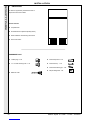
The Floor Standing Gas Boiler
The Ideal Mexico is a range of cast iron floor standing gas central heating boilers. Both
balanced or conventional flue versions are available. A complete range of both natural
gas and propane models. The range offers Super models and, for when space is tight,
there are Slimline models available.
Mexico: Britain’s biggest selling floor standing boiler
The ideal replacement boiler...
Easy to install, easy to operate and easy to service. The Ideal Mexico really is the ultimate
replacement floor standing range - you can depend on it.
Proven reliability...
Proven cast iron heat exchanger engineered and refined to be the most dependable floor
standing boiler ensuring totally calm operation and quiet running, whatever the system
demands.
Complete range...
27 models, including 4 Slimline models at only 250mm wide and 8 propane Super models.
Option kit availability includes an easy to use programmer kit available on all models, an
overheat thermostat kit for all models and a pump kit that can be housed within the
casing, available for all models except the Super CF 3/140 & CF 3/140P.
Full system suitability...
All models are suitable for connection to pumped open vent central heating systems,
pumped central heating combined with pumped or gravity indirect domestic hot water
supply systems. They can also be used on sealed water systems when used in conjunction
with the optional Overheat Thermostat Kit.
Free Guarantee: 1st Year Ideal Care
The home owner is entitled to 12 months free Ideal Care, which includes both parts and
labour, to restore the boiler to full function. Please encourage the home owner to complete
and return the registration form in their Householder’s pack within 30 days of installation.
Optional Extra Year Cover with Ideal Care
You may wish to offer your own annual service plan or you may wish to advise the home
owner to complete their application form for the appropriate level of extended Ideal Care -
Silver, Gold or Platinum. Full details are available in the Ideal Care brochure.
CAUTION.
To avoid the possibility of injury during the installation, servicing or cleaning
of this appliance, care should be taken when handling edges of sheet steel components.

3
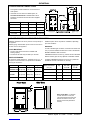
Mexico Super CF 3/60P - 3/140P - Installation
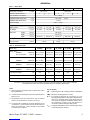
Boiler Size CF 3/60P CF 3/75P CF 3/100P CF 3/125P CF 3/140P
Gas Supply Connection in. BSP Rc 1/2 (1/2) Rc 3/4 (3/4)
Number of Boiler Sections 3 3 4 5 6
Flow and Return Connections Rc 1 (1" BSP)
MAXIMUM Static Water Head m (ft.) 30.5 (100) (3 bar)
MINIMUM Static Water Head m (ft.) 1.0 (3.3)
Electrical Supply 230 V ~ 50 Hz
External Fuse Rating (Power Consumption) 3 A (5 W)
Water Content litre (gal.) 7.4 (1.6) 7.4 (1.6) 9.8 (2.1) 12.2 (2.7) 14.6 (3.2)
Dry Weight kg. (lb.) 89 (196) 89 (196) 111 (245) 134 (295) 157 (346)
Boiler Size Height mm (in.) 850 (33.5)
Width mm (in.) 440. (17.4)
Depth mm (in.) 533 (21.0) 533 (21.0) 533 (21.0) 600 (23.6) 750 (29.5)
Gas Type II 2H 3P
Flue Connection mm (in.) 100 (4) 125 (5) 150 (6)
Table 1 - Boiler Data
GENERAL
Boiler Size CF 3/60P CF 3/75P CF 3/100P CF 3/125P CF 3/140P
Boiler Input
NOMINAL kW (Btu/h) 22.1 ( 75 400) 27.3 (93 100) 35.8 (122 100) 43.4 (148 100) 53.5 (182 500)
Gas Consumption l/s (ft.3/h) 0.246 (31.8) 0.287 (37.1) 0.377 (48.8) 0.457 (59.2) 0.563 (72.9)
Boiler Output to Water
NOMINAL kW (Btu/h) 18.1 (61 600) 22.2 (75 800) 29.3 (100 000) 35.6 (121 600) 44.3 (151 100)
Burner Setting Pressure (hot)
NOMINAL mbar (in w.g.) 35.4 (14.2) 35.0 (14) 35.0 (14) 35.1 (14) 34.9 (14)
Inlet Pressure
NOMINAL mbar (in w.g.) 37.0 (14.8) 37.0 (14.8) 37.0 (14.8) 37.0 (14.8) 37.0 (14.8)
Flue Gas Flow Rate g/s 10.6 13.1 17.2 20.8 25.7
Flue Gas Temperature oC 125 134 129 140 132
Seasonal Efficiency(SEDBUK)* % 72.7 72.3 72.0 72.8 73.0
Table 2 - Performance Data
Notes.
1. Gas consumption is calculated using a calorific value of 95.0
MJ/m3 (2500 Btu/ft.3.)
2. To obtain the fuel consumption in liquid form divide the above
figures by 270.
3. The appliance is pre-set at the factory to give the nominal
output at an inlet pressure of 37 mbar (14.8 in.w.g.)
4. A conversion kit is available to convert this appliance for use
on natural gas. This kit contains all parts and istructions for
setting up on natural gas. Once converted it is not possible
to convert back to propane.
Key to symbols
GB = United Kingdom IE = Ireland (Countries of destination)
PMS = Maximum operating pressure of water
B11BS = An appliance designed for connection to a flue
discharging the products of combustion outside the room,
with air for combustion being drawn directly from the
room where the appliance is installed, without a fan in
the combustion products circuit and fitted with a
combustion products discharge safety device.
II2H3P = An appliance designed for use on 2nd Family gas, Group
H and 3rd Family gas, Group P.
*The value is used in the UK government's Standard Assessment Procedure (SAP) for energy rating of dwellings.
The test data from which it has been calculated have been certified by BGplc 0087)

4Mexico Super CF 3/60P - 3/140P - Installation
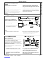
The Mexico Super CF propane range is of floor standing,
natural draught, open flue gas boilers. They are range-rated to
provide central heating outputs of 18.1kW (61 600 Btu/h) to
44.3 kW (151 100 Btu/h).
The boiler has a cast iron heat exchanger and is supplied fully
assembled, complete with a white enamelled mild steel casing.
The boilers are suitable, as standard, for connection to open-
vented systems ONLY. An overheat thermostat kit is available
to allow the boiler to be used on sealed water systems.
The systems may be:
zpumped or gravity circulating indirect DHW only.
zpumped central heating only.
zpumped central heating combined with either a pumped or
gravity circulating indirect DHW circuit.
OPTIONAL EXTRA KITS
Programmer Kit Fits neatly within the casing. Separate
fitting instructions are included with this kit.
Pump Kit Fits neatly within the casing. Separate
fitting instructions are included with this kit.
Overheat Available to allow the boiler to be used
Thermostat Kit on sealed water systems.
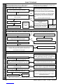
GENERAL
CONTENTS
Air Supply. ...................................................................... 7
Boiler Assembly - Exploded view ................................ 9
Boiler Clearances ......................................................... 6
Burner Assembly - Exploded view ................... 39 & 40
Control Panel Assembly - Exploded view ................. 41
Downdraught Thermostat ............................................. 7
Electrical Connections ............................................... 15
Electrical Diagram ...................................................... 15
Electrical Supply ........................................................... 8
Fault Finding ................................................................ 34
Flue Fitting ................................................................... 14
Flue Installation ............................................................. 7
Gas Safety ..................................................................... 5
Gas Supply ..................................................................... 5
Initial Lighting ............................................................... 19
Installation ..................................................................... 9
Mandatory Requirements ............................................. 5
Pump ............................................................................ 14
Servicing ...................................................................... 21
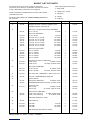
Short List of Parts ....................................................... 35
System Electrical Diagrams ...................................... 16
Water Circulation .......................................................... 8
Water Connections ....................................................... 6
Water Systems ............................................................ 12
Mexico Super CF 3/60P G.C. No. 41 348 99
Mexico Super CF 3/75P G.C. No. 41 349 23
Mexico Super CF 3/ 100P G.C. No. 41 349 24
Mexico Super CF 3/ 125P G.C. No. 41 349 25
Mexico Super CF 3/ 140P G.C. No. 41 349 26
Mexico Super CF - Propane
INTRODUCTION
Propane only Appliance type: B11 BS
B.G. Certified - P.I. No. 87 AT 15
Destination Countries: GB, IE
NOTE TO THE INSTALLER:
LEAVE THESE
INSTRUCTIONS ADJACENT TO THE GAS METER.
ALSO COMPLETE THE BENCHMARK LOG BOOK
AND GIVE THIS TO THE CUSTOMER.

5
Mexico Super CF 3/60P - 3/140P - Installation
GENERAL
LOCATION OF BOILER
The boiler must be installed on a flat and level floor, capable of
adequately supporting the weight of the boiler and any
ancillary equipment.
The boiler may be fitted on a combustible floor.
Insulation is not necessary, unless required by the local
authority.
The boiler must not be fitted outside.
The boiler must not be installed in a bedroom or in a room
containing a bath or shower.
Timber Framed Buildings
If the boiler is to be fitted in a timber framed building it should
be fitted in accordance with the Institute of Gas Engineering
document IGE/UP/7:1998.
Compartment Installations
A compartment used to enclose the boiler MUST be designed
and constructed specially for this purpose.
An existing cupboard or compartment may be used, providing it
is modified for the purpose.
Details of essential features of cupboards /compartment
design, including airing cupboard installation, are to conform to
the following:
zz
zz
zBS. 6798.
zz
zz
zThe position selected for installation MUST allow
adequate space for servicing in front of the boiler
and for air circulation around the boiler.
Side clearance is only necessary for installation. The
amount of side clearance will depend upon the type of
connection used.
zThis position MUST also permit the provision of a
satisfactory flue and an adequate air supply.
zFor the minimum clearances required for safety, and
subsequent service, see Frame 2.
GAS SUPPLY
The local propane supplier should be consulted, at the
installation planning stage, in order to establish the availability
of an adequate supply of gas.
Check that the appliance is suitable for the proposed gas
supply.
Installation pipes, cylinders and pressure regulators should be
fitted in accordance with BS. 5482.1.
Bulk tank installations must comply with the Home Office code
of practise for the storage of liquified petroleum gas at fixed
installations.
The complete installation MUST be tested for gas soundness
and purged as described in the above code.
GAS SAFETY
Gas Safety (Installation and Use) Regulations 1994,
amendments 1996 or rules in force.
It is law that all gas appliances are installed by a CORGI
registered installer (identified by ) in accordance with the
above regulations. Failure to install appliances correctly could
lead to prosecution. It is in your own interest, and that of safety,
to ensure the law is complied with.
The installation of the boiler MUST also be in accordance with
the latest I.E.E. (BS 7671) Wiring Regulations, local building
regulations, bylaws of the local water authority, the Building
Regulations and Building Standards (Scotland) and any
relevant requirements of the local authority.
Detailed recommendations are contained in the following
British Standard Codes of Practice:
BS. 6891 Low pressure installation pipes.
BS. 6798 Installation of gas fired hot water boilers of rated
input not exceeding 60 kW.
BS. 5449:1 Forced circulation hot water systems (small bore
and microbore domestic central heating systems).
BS. 5546 Installation of gas hot water supplies for domestic
purposes (2nd Family Gases).
BS. 5440: 1 Flues for gas appliances of rated input not
exceeding 60 kW.
BS. 5440: 2 Ventilation for gas appliances of rated input not
exceeding 60 kW.
BS 7593 Treatment of water in Domestic Hot Water Central
Heating Systems.
Health and Safety Document No. 635.
The Electricity at Work Regulations, 1989.
Manufacturer’s notes must NOT be taken in any way as
overriding statutory obligations.
IMPORTANT.
These appliances are certificated by the British Standards
Institution for safety and performance. It is important, therefore,
that no external control devices, e.g. flue dampers,
economisers etc., are directly connected to these appliances
unless covered by these Installation and Servicing Instructions
or otherwise recommended by Caradon Plumbing Ltd. in
writing. If in doubt please enquire.
Any direct connection of a control device not approved by
Caradon Plumbing Ltd. could invalidate the BSI Certification
and the normal appliance warranty. It could also infringe the
Gas Safety Regulations and the above regulations or other
statutory requirements.

6Mexico Super CF 3/60P - 3/140P - Installation
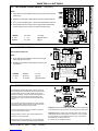
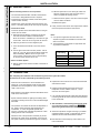
Boiler Dim. A Dim. B Dim. C
CF 3/60P & 3/75P 218 (8 5/8") 122 (4 3/4") 533 (21")
CF3/100P 291 (11 1/2") 122 (4 3/4") 533 (21")
CF 3/125P 363 (14 1/4") 122 (4 3/4") 600 (23 5/8")
CF 3/140P 436 (17 1/8") 202 (8") 750 (29 1/2")
GENERAL
1
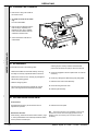
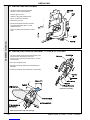
BOILER WATER CONNECTIONS
2
FLOOR MOUNTING AND BOILER CLEARANCES
Flammable materials must not be placed in close proximity to
the appliance.
Materials giving off flammable vapours must not be stored in
the same room as the appliance.
.
FLOOR MOUNTING
1. The floor must be flat, level and of suitable load
bearing capacity.
2. The back of the boiler may be fitted up to the wall.
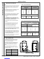
BOILER CLEARANCES
The minimum overall dimensions - measured in mm (in.) - of
the space in which the boiler is to operate and to facilitate
servicing are as follows:-
Boiler Clearances Top One side Aggregate
mm. (in) 'A' or 'B' 'A' + 'B'
CF 3/60P & 3/75P 20 (3/4) 10 (3/8) 110 (4 1/2)
CF 3/100P 20 (3/4) 35 (1 3/8) 135 (5 1/4)
CF 3/125P 20 (3/4) 50 (2) 210 (8 1/4)
CF 3/140P 20 (3/4) 150 (6) 300 (12)
Note. 3/100P ONLY. If minimum
LH side clearance is used, the
TTB downdraught thermostat and
bracket should be moved to the
RH side of the boiler (alternative
location).
Boiler Size Width Depth Height
CF3/60P & 75P 550 (21 5/8) 535 (21) 870 (34 1/4)
CF3/100P 575 (22 5/8) 535 (21) 870 (34 1/4)
CF3/125P 650 (25 5/8) 600(23 5/8) 870 (34 1/4)
CF3/140P 740 (29 1/8) 750 (29 1/2) 870 (34 1/4)
IMPORTANT.
In order to facilitate gas connection, a clearance of at least 100
mm (4") must be available at either the LH side or the RH side
DURING installation. Refer to Frame 7.
A MINIMUM clearance of 25mm (1") MUST also be maintained
between the flue pipe and any adjacent combustible material.
In addition a MINIMUM clearance of 533 mm (21") MUST be
available at the front of the boiler, for servicing.
Additional space will be required for installation, depending
upon site conditions.
1. This appliance is NOT suitable for use in a direct hot
water system.
2. If the boiler is to be used on a sealed system, an
Overheat Thermostat Kit is available and must be
installed in accordance with the instructions supplied
with the kit.

7
Mexico Super CF 3/60P - 3/140P - Installation
GENERAL
downdraught, probably as a result of adverse wind conditions .
The TTB is an automatic reset thermostat which will reset once
the wind conditions have returned to normal, subject to a built-
in reset delay in excess of 10 minutes
The TTB is an important safety device and must not be put out
of action or interfered with in any way.
This device in not a substitute for an independently mounted
carbon monoxide detector.
In cases of repeated or continuous shutdown a competent
person should be called to investigate and rectify the condition
causing this and carry out an operational test after each
intervention on the device. Only the manufacturer's original
parts should be used for replacement.
AIR SUPPLY
Detailed recommendations for air supply are given in
BS.5440:2. The following notes are for general guidance:
1. The room or internal space in which the boiler is installed
MUST have, or be provided with, a permanent air vent. This
vent MUST be either direct to outside air or to an adjacent
room or internal space which must itself have, or be
provided with, a permanent air vent at least the same size
direct to outside air.
The minimum effective area of the permanent air vent(s) are
FLUE INSTALLATION
The flue must be installed in accordance with the
recommendations of BS. 5440:1.
The following notes are intended for general guidance:
1. The cross-sectional area of the flue, serving the boiler,
MUST NOT be less than the area of the flue outlet of the
boiler.
If flue pipe is to be used it MUST NOT be less than the
diameter of the flue outlet connection on the boiler.
2. Flue pipes and fittings should be constructed from one of
the following materials:
a. Aluminium or stainless steel.
b. Cast iron, coated on the inside with acid resistant
vitreous enamel.
c. Other approved material.
3. If twin walled flue pipe is used it should be of a type
acceptable to British Gas.
4. If a chimney is to be used it should preferably be one that is
composed of, or lined with, a non-porous acid resistant
material.
Notes.
Chimneys lined with salt -glazed earthenware pipes are
acceptable if the pipes comply with BS.65 and BS.5440:1.
A flue pipe constructed from one of the materials listed in
2 a-c should form the initial connection to the lined
chimneys.
Where a chimney is to be used that is not composed of, or
lined with, a non-porous, acid resistant material it should be
lined with a stainless steel flexible flue liner which complies
with BS.715.
5. Before connecting the boiler to, or inserting a liner into, a
flue that has been previously used then the flue MUST be
thoroughly swept clean of any soot or loose material. If a
register plate, restrictor plate or damper etc., is fitted in the
flue then it MUST be removed before connecting the boiler
to, or inserting a liner into, the flue.
6. The flue should terminate in accordance with the relevant
recommendations given in BS.5440:1.
7. The flue MUST be fitted with a terminal (or ridge tile up to 5"
flue diameter). The terminal shall be of a type which has
been tested and found satisfactory by British Gas. This
terminal must NOT be installed within 600mm (24") of an
opening window, air vent or any other ventilation opening.
8. The chimney / flue lining MUST be sealed at both the top
and the bottom.
IMPORTANT. It is absolutely ESSENTIAL to ensure, in practice,
that the flue discharge is in a downdraught- free zone and that
products of combustion discharging from the terminal cannot
re-enter the building or any other adjacent building through
ventilators, windows, doors, other sources of natural air
infiltration or forced ventilation / air conditioning systems.
TTB DOWNDRAUGHT THERMOSTAT
This appliance is fitted with a TTB downdraught thermostat for
added safety and protection. If this thermostat should operate
and switch off the appliance it is because the flue is subject to
specified below and are related to maximum rated heat
input of the boiler -see Table 3.
The air vent(s) must NOT have provision for closing or
adjustment and should be sited to avoid risk of accidental
damage or blockage.
If other methods of ventilation are envisaged, British Gas
should be consulted before proceeding.
2. If the boiler is to be installed in a cupboard or compartment,
permanent air vents are required (for combustion, flue
dilution and cooling purposes) in the cupboard /
compartment, at both high and low levels to ensure safe
and efficient combustion and ventilation.
The air vents may either communicate with room/internal
space (appropriately ventilated) or be direct to outside air.
The minimum effective areas of the permanent air vents,
required in the cupboard / compartment, are specified as
follows and are related to maximum rated heat input of the
boiler (see Table 4).
Notes.
a. Both air vents MUST communicate with the same room or
internal space or MUST be on the same wall to outside air.
b. In siting the air vents care must be taken to avoid the
freezing of pipework.
c. Where cupboard / compartment air vents are open to a
room or internal space, the room or internal space MUST
itself be provided with a permanent air vent, as previously
specified.
d. The cupboard / compartment air vents must NOT
communicate with a bedroom, bed-sitting room or a room
containing a bath or shower.
Boiler size 3/60P 3/75P 3/100P 3/125P 3/140P
cm274 101 135 179 216
(in2) (12) (16) (21) (28) (34)
Table 3
Effective
area

8Mexico Super CF 3/60P - 3/140P - Installation
GENERAL
Water Flow Rate and Pressure Loss
Boiler Air from room/internal Air direct from outside
space cm2 (in.2)cm
2 (in.2)
High Level Low Level High level Low Level
CF 3/60P 211(33) 422 (66) 106 (17) 211 (33)
CF 3/75P 264 (41) 528 (82) 132 (21) 264 (41)
CF 3/100P 333 (52) 666 (100) 167 (26) 333 (52)
CF 3/125P 420 (65) 840 (130) 210 (33) 420 (65)
CF 3/140P 495 (77) 990 (154) 248 (39) 495 (77)
Table 4 - High and low vent areas
EFFECT OF AN EXTRACTOR FAN
If there is any type of extractor fan fitted in the premises there is
a possibility that, if an adequate air inlet area from outside is
not provided, spillage of the boiler flue products could occur
when the fan is in operation. Where such installations occur a
spillage test, as detailed in BS.5440:1, MUST be carried out
and any necessary action taken.
VENTILATION IN SERIES
In installations requiring 2 ventilators to be fitted in series, e.g.
across a cavity wall, EACH ventilator should be sized in
accordance with the above data. Where there are more than 2
ventilators in series, EACH should have an area of 50% in
excess of the value quoted above.
WATER CIRCULATION SYSTEM
The boiler must NOT be used for direct hot water supply.
The boiler is suitable for connection to pumped open vent
central heating systems, pumped central heating combined
with pumped or gravity indirect domestic hot water supply
systems and gravity or pumped indirect domestic hot water
supply systems.
The boiler is NOT suitable for gravity heating systems.
The hydraulic resistances of the boiler at maximum output with
11 0C (20 0F) temperature differentials are shown in the
following graph:
Dotted lines indicate flow rates equivalent to a temperature rise
of 110C (200F)
The central heating system should be in accordance with
BS. 6798 and, in addition, for smallbore and microbore
systems, BS. 5449:1.
The domestic hot water system, if applicable, should be in
accordance with the relevant recommendations of BS. 5546.
Copper tubing to BS. 2871:1 is recommended for water
carrying pipework.
The hot water storage cylinder MUST be of the indirect type
and should preferably be manufactured of copper.
Single feed, indirect cylinders are not recommended and must
NOT be used on sealed systems.
The hot water cylinder and ancillary pipework not forming part
of the useful heating surface should be lagged to prevent heat
loss and any possible freezing - particularly where pipes run
through roof spaces and ventilated underfloor spaces.
IMPORTANT
The boiler must be vented. If venting cannot be done via a flow
connection a separate vent MUST be fitted by the installer.
Draining taps MUST be located in accessible positions, which
permit the draining of the whole system, including the boiler
and hot water storage vessel. They should be at least 1/2" BSP
nominal size and be in accordance with BS. 2879.
If required, a drain tap (not supplied) may be fitted to an unused
bottom (1" BSP) tapping on the front of the boiler.
THERMOSTATIC RADIATOR VALVES
Caradon Plumbing Ltd. recommend that heating systems
utilising full thermostatic radiator valve control of temperature in
individual rooms should also be fitted with a room thermostat
controlling the temperature in a space served by radiators not
fitted with such a valve, as stated in BS. 5449.
When thermostatic radiator valves are used, the space heating
temperature control over a living / dining area or hallway
having a heating requirement of at least 10% of the boiler heat
output should be achieved using a room thermostat, whilst
other rooms are individually controlled by thermostatic radiator
valves. However, if the system employs thermostatic radiator
valves on all radiators, or two port valves without end switches
then a bypass must be fitted in order to ensure a flow of water
should all the valves be in the closed position.
ELECTRICAL SUPPLY
WARNING. The appliance MUST be efficiently earthed.
Wiring external to the appliance MUST be in accordance with
the current I.E.E. (BS 7671) Wiring Regulations and any local
regulations which apply.
The boiler is supplied for 230 V ~ 50Hz single phase.
Fuse rating is 3A.
Connection must be made in a way that allows complete
isolation of the electrical supply such as a double pole switch
having 3mm (1/8") contact separation in both poles, or a plug
and socket, serving only the boiler and system controls. The
means of isolation must accessible to the user after installation.

9
Mexico Super CF 3/60P - 3/140P - Installation
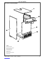
INSTALLATION
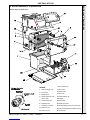
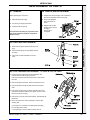
3
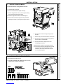
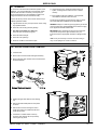
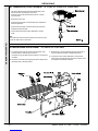
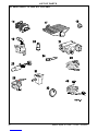
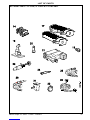
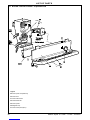
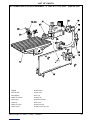
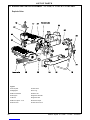
BOILER ASSEMBLY - Exploded View
LEGEND
1. Heat exchanger assy.
2. End section.
3. Middle section.
4. Section alignment rings
and 'O' rings.
5. Thermostat pocket.
6. Distributor tube.
7. Combustion chamber.
11. Collector hood.
12. Cleanout cover.
Mexico Super CF 3/60P shown
13. Front plate assy.
21. Gas valve.
23. Piezo igniter.
27. Gas cock.
33. Phial retaining clip.
34. Split pin.
45. Flue baffle.
46. Boiler base plate.
48. Draught diverter back panel assembly
49. TTB downdraught thermostat & bracket.
50. Heat shield.
INSTALLATION

10 Mexico Super CF 3/60P - 3/140P - Installation
Pack A Contents
zcomplete boiler
zthe Hardware Pack (listed separately below)
zthese Installation and Servicing Instructions
zUser's Instructions.
INSTALLATION
INSTALLATION
The boiler is supplied fully assembled in Pack A.
Unpack and check the contents.
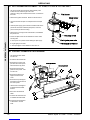
4
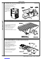
UNPACKING
HARDWARE PACK
z1" BSP plugs - 6 off
z1" x 1/2" BSP reducing bush - 1 off
zDistributor tube
zThermostat pocket -1 off
zThermostat clip - 1 off
zThermostat retaining pin - 1 off
zOutput setting label -1 off

11
Mexico Super CF 3/60P - 3/140P - Installation
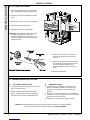
5
BOILER CASING REMOVAL
INSTALLATION
INSTALLATION
To install the boiler the casing MUST be removed.
6
CHECKING THE FLUEWAY BAFFLES
1. Lift off the lower front panel.
2. Remove 2 screws and lift off grille assembly.
3. Remove the gas valve cover by removing the retaining
screw. Disconnect the electrical leads.
4. Release the gas valve lead from the retaining clip.
5. Remove the 2 screws securing the control panel and
disengage the panel by lowering and pulling it forward.
6. Remove the 2 screws securing the top panel to
the side.
7. Draw the top panel forward and lift it off the boiler.
8. Remove the 2 screws securing LH side panel to
the flue collector and baseplate.
9. Pull the panel forward, lifting it clear of the
locating peg and remove.
10. Repeat steps 7 and 8 to remove the RH panel.
11. The boiler is held to the packaging base by 4 M6
hex head screws. Remove the front screws,
slacken the rear screws and remove the boiler
from the packaging base.
1. Remove the flue cleanout cover.
2. CF 3/75P, CF 3/100P & CF 3/140P only. Ensure that the
baffles are fully inserted in the flueways.

12 Mexico Super CF 3/60P - 3/140P - Installation
Boiler size Dim. A
CF 3/60P & 3/75P 410 (16 1/8")
CF 3/100P 483 (19")
CF 3/125P 553 (21 3/8")
CF 3/140P 702 (27 5/8")
Table 6 - Gravity Domestic Hot Water & Pumped Central Heating
Connections - as viewed at front Thermostat Position
Back Section Front Section
CH DHW
Flow Return Flow Return Top
LH LH RH RH LH
LH RH RH LH LH
RH RH LH LH RH
RH LH LH RH RH
CF 3/140P ONLY
LH LH RH RH LH
RH RH LH LH RH
Table 5 - Fully Pumped Systems
Connections - as viewed at front Thermostat position
Back Section Front Section
Flow Return Top
LH LH LH
LH RH LH
RH RH RH
RH LH RH
CF 3/140P ONLY
LH LH LH
RH RH RH
INSTALLATION
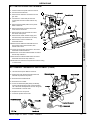
7
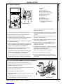
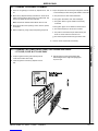
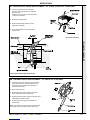
PREPARING THE BOILER
Notes.
zBefore placing the boiler in the selected position any
gas and water connections at the rear of the boiler
should be prepared, due to the possible lack of
access.
zIf an optional Pump Kit is to be used then it must be
fitted at this stage. Refer to separate fitting
instructions included with the kit.
1. Screw the distributor tube (supplied with a 1" BSP x
28mm copper adaptor) into the selected heating
return tapping, using an appropriate jointing
material.
It is IMPERATIVE that the INDEX MARK on the
distributor bush is in alignment with the mark on
the section boss, as shown in Frame 3.
DO NOT disturb it when connecting subsequent
pipework.
Fully pumped systems using more than 1 pump,
serving separate zones, must have a common
return connection to the distributor tube.
2. Select the desired pumped flow tapping.
3. Screw the supplied boiler thermostat pocket into the
appropriate front section tapping, using an approved
jointing material. Refer to Tables 5 and 6.
4. Connect pipe fittings to the rear tappings and plug
any unused tappings. Note. If using iron elbows fit a
short straight connector into the boiler tapping first,
to clear the casing when fitted.
5. Place the boiler in position. Note. The pump may be
fitted on the FLOW or RETURN.
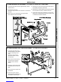
INSTALLATION
8
GAS CONNECTION
1. A MINIMUM working gas pressure of 37 mbar
(14.8 in.w.g.) MUST be available at the boiler
inlet, with the boiler operating.
2. Extend a gas supply pipe to the boiler (for size
refer to Table 1 on page 3) and connect to the
gas cock situated at the front LH side of the
boiler.
3. Test the gas installation for soundness and
purge in accordance with BS.6891: 1988. Refer
to Frame 22 , item B.

13
Mexico Super CF 3/60P - 3/140P - Installation
INSTALLATION
INSTALLATION
9
WATER CONNECTION
1. Connect the system flow and return pipework to the
boiler as appropriate. Refer to Frames 10 and 11 for
guidance on system design.
Connection sizes
All water connections are RC 1 (1" BSP) but pumped
pipework must be increased to:
CF 3/125P only 35 mm (1 1/4" BSP)
CF 3/140P only 42mm (1 1/2" BSP)
immediately after leaving the boiler.
Gravity pipework and connections must be at least:
CF 3/100P & 3/125P only 28 mm (1" BSP)
CF 3/140P only 35mm (1 1/2" BSP)
2. Ensure that all valves are open. Fill and vent the system
and check for water soundness.
Notes.
a. Isolating valves must be fitted as close to the pump as
possible.
b. The boiler is not suitable for use with a direct hot water
cylinder or a sealed system.
10
MINIMUM REQUIREMENTS Fully pumped systems
1. Open vent and cold feed connections must be
made to the boiler flow and return tappings
according to the options shown in Frame 7.
2. The boiler is assumed to be the highest
point of the circulating system.
3. The circulating pump is positioned on the
FLOW - the vertical distance, between the
pump and feed/ expansion tank, must
comply with the pump manufacturer's
minimum requirements, to avoid cavitation.
Should these conditions not apply, either
lower the pump position or raise the feed/
expansion tank above the minimum
requirements of Caradon Plumbing Ltd.
4. The water velocity through the boiler flow /
return pipes is assumed to be below 1 m/s
(3 ft./s.) whilst the pump flow rate is set to
provide a temperature difference of 110C
(200F) across the boiler flow / return, at
design input.
5. This information is intended as a GUlDE
ONLY and cannot take into account
instantaneous changes in head caused by
the operation of motorised valves, pumps
etc.
Due allowance MUST be made if surging is
liable to occur.
If in any doubt, contact Caradon Plumbing Ltd.

14 Mexico Super CF 3/60P - 3/140P - Installation
11
GRAVITY HOT WATER & PUMPED CENTRAL HEATING
INSTALLATION
INSTALLATION
12
FLUE CONNECTION
Connect the flue pipe to the flue outlet.
The flue pipe spigot and socket connections should be sealed
with fibreglass rope, or similar, and suitable fireclay cement.
Notes.
a. The boiler flue connection outlet size is suitable for flue pipe
conforming to BS 567.
If sheet steel flue pipe is fitted, a suitable adaptor must be
used.
b. To facilitate installation and subsequent disconnection it is
recommended that a slip or split socket be included in the
flue installation, adjacent to the boiler flue outlet connection.
c. A minimum of 600mm (2') of vertical flue directly above the
boiler should be provided.
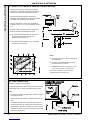
1. Separate flow and return connections are used for
each service. All possible configurations are given in
Frame 7 and ONLY those shown should be used.
2. The schematic pipework graph is based on the
assumption that NO MORE than 8 elbows are used in
the gravity loop, including entry to the boiler.
3. For each extra elbow in excess of 8, (R) MUST be
reduced by 300 mm (12") or (H) increased by 100 mm
(4")
4. Whatever value is selected for (R), the value of (H)
MUST be at least that indicated by the graph
(R) = the horizontal distance between the centre line of
the cylinder and the boiler tappings used -
measured along the pipe run
(H) = the vertical distance between the top of the boiler
and the base of the cylinder
Notes.
a. Flow and return pipes should rise vertically on
leaving the boiler.
b. Horizontal pipes should be ABOVE ceiling
level and as short as possible.
c. A MINIMUM inclination of 25 mm per 3 m run
(1" per 10') is required to avoid air locks.
If the above conditions cannot be met then
pumped primaries should be used.

15
Mexico Super CF 3/60P - 3/140P - Installation
13
ELECTRICAL CONNECTIONS
INSTALLATION
INSTALLATION
14
INTERNAL WIRING
15
EXTERNAL CONTROLS
External wiring must be in accordance with the current I.E.E.
(BS 7671) Wiring Regulations.
The wiring diagrams illustrated in Frames 17-19 cover the
systems most likely to be fitted to this appliance.
For wiring external controls to the Mexico Super CF P boiler
reference should be made to the system wiring diagrams
supplied by the relevant manufacturer, in conjunction with this
flow wiring diagram and Frame 14.
Difficulty in wiring should not arise, providing the following
directions are observed:
3. If a proprietary system is used, follow the instructions
supplied by the manufacturer.
Advice on required modifications to the wiring may be
obtained from the component manufacturers.
Note. If there are no external controls the circulating pump
MUST be wired into the control box.
1. Controls that switch the system on and off, e.g. a time
switch, MUST be wired, in series, in the live mains lead
to the boiler.
2. Controls that override an on/off control, e.g. a frost
thermostat, MUST be wired into the mains lead, in
parallel, with the control(s) to be overridden. Refer to
Frame 20.
WARNING.
The appliance MUST be efficiently earthed.
A mains supply of 230 V ~ 50 Hz fused at 3A is required.
All external controls and wiring MUST be suitable for mains
voltage.
Wiring should be in 3-core PVC insulated cable NOT LESS
than 0.75 mm2 (24 x 0.2 mm) to BS.6500, Table 16.
Wiring external to the boiler MUST be in accordance with
current l.E.E. (BS 7671) Wiring Regulations and local
regulations.
Connection must be made in a way that allows complete
isolation of the electrical supply - such as a double pole
switch, having a 3mm (1/8") contact separation in both poles,
or a plug and socket serving only the boiler and system
controls.
The means of isolation must be accessible to the user after
installation (except in the case of bathroom installations for
domestic boilers where the point of connection to the mains
MUST be outside of the bathroom).
Flow and pictorial wiring diagrams are shown
in Frames 17 and 18. A schematic wiring
diagram is included in the Lighting Instruction
label.
1. Remove the securing screw and lift off the
control box cover.
2. Route the electrical leads into the box and
wire into the terminal strip, as shown.
Notes.
a. Secure each lead with one of the cable clamps. b. The mains lead connection MUST be made so that, should
the lead slip from its anchorage, the current conductors
become taut before the earthing conductor.

16 Mexico Super CF 3/60P - 3/140P - Installation
INSTALLATION
INSTALLATION
16
PICTORIAL WIRING
LEGEND
bblue
bk black
br brown
y/g yellow/green
or orange
wwhite
gy grey
y/g yellow/green
LEGEND
bblue
bk black
br brown
rred
17
MID POSITION VALVE Pumped only
Notes.
1. Some earth wires are omitted for
clarity. Ensure proper earth
continuity when wiring.
2. Numbering of terminals on
thermostats is specific to the
manufacturer.
3. This is a fully controlled system - set
the boiler thermostat to maximum.
4. 'Switchmaster Midi' is similar in
operation but the wiring differs
slightly; see manufacturer's
literature.

17
Mexico Super CF 3/60P - 3/140P - Installation
INSTALLATION
INSTALLATION
18
TWO SPRING CLOSED VALVES
Notes.
1. Some earth wires are omitted for clarity. Ensure proper earth continuity
when wiring.
2. Numbering of terminals on thermostats is specific to the manufacturer.
3. This is a fully controlled system - set the boiler thermostat to maximum.
4. 'Switchmaster Autozone' has grey and orange auxiliary switch leads
but the orange wire only must be connected to the live supply.
LEGEND
bblue
bk black
Pumped only
19
HONEYWELL 'C' PLAN
Notes.
1. Some earth wires are omitted for clarity. Ensure proper
earth continuity when wiring
2. Numbering of terminals on thermostats is specific to the
manufacturer.
LEGEND
wwhite
rred
bk black
br brown
or orange
bblue
gy grey
g/y green/yellow
20
FROST PROTECTION
br brown
rred
wwhite
or orange
g/y green/yellow
gy grey
Diagram A shows a double pole frost thermostat, which should suffice
for all systems which do not use the OFF terminals of the programmer.
Diagram B shows a 'change-over' frost thermostat, which will cover
most systems which do use CH OFF. If, however, on such a system
the HW pipework is in an isolated part of the house, a second frost
thermostat may be used to protect it.
If in doubt, ask your installer for advice.
Central heating systems fitted wholly inside the house do
not normally require frost protection as the house acts as a
'storage heater' and can normally be left at least 24 hrs.
without frost damage. However, if parts of the pipework run
outside the house or if the boiler will be left off for more
than a day or so then a frost 'stat should be wired into the
system.
This is usually done at the programmer, in which case the
programme selector switches are set to OFF and all other
controls MUST be left in the running position.
The frost 'stat should be sited in a cold place but where it
can sense heat from the system.
Wiring should be as shown, with minimal disturbance to
other wiring of the programmer.
Designation of the terminals will vary, but the programmer
and thermostat manufacturers' leaflets will give full details.
Gravity HW & Pumped CH

18 Mexico Super CF 3/60P - 3/140P - Installation
INSTALLATION
WARNING. Whilst effecting the required gas soundness test and purging air from the gas installation,
open all windows and doors, extinguish naked lights and DO NOT SMOKE.
INSTALLATION
21
FITTING THE CASING
22
COMMISSIONING AND TESTING
A. ELECTRICAL INSTALLATION
1. Checks to ensure electrical safety should be carried
out by a competent person.
2. ALWAYS carry out preliminary electrical system
checks, i.e. earth continuity, polarity, resistance to
earth and short circuit using a suitable test meter.
B. GAS INSTALLATION
1. The whole of the gas installation, including the meter,
MUST be inspected and tested for soundness, and
purged in accordance with the recommendations of
BS. 6891.
2. Purging air from the gas installation may be expedited by
loosening the union on the gas service cock on the boiler
and purging until gas is detected.
3. Retighten the union and check for gas soundness.
1. Offer up the RH side panel, locating it with the
peg in the baseplate, and push the panel back.
2. Secure the panel to the baseplate and collector
hood.
3. Repeat steps 1 and 2 to refit the LH side panel.
4. Place the top panel and push back.
5. Secure the top panel to the side panels.
IMPORTANT. Wiring within the boiler casing must
be neartly secured with the cable straps
provided and MUST NOT be allowed to touch
the burner front plate, or the cleanout cover and
the collector hood.
6. Replace the control box cover and refit the
control panel using the screws previously
removed.
7. Insert the thermostat phial and phial retaining
clip into the thermostat pocket. Take care not
to kink the thermostat capillary as it is
unwound andsecure it with the split pin as
shown.
8. Refit the grille assembly

19
Mexico Super CF 3/60P - 3/140P - Installation
INSTALLATION
INSTALLATION
23
INITIAL LIGHTING
24
PILOT BURNER CONNECTION GAS SOUNDNESS
1. Turn the gas service cock to OFF and undo the union nut.
2. Remove the 4 wing nuts and withdraw the burner and controls
assembly, complete, from the boiler.
3. Invert the burner assembly and reconnect to the gas service cock.
4. Turn the gas service cock to ON.
5. Light the pilot burner. Refer to Frame 23.
6. Test for gas soundness around the pilot burner connection, using
leak detection fluid.
7. Turn the gas service cock to OFF and return the burner and
controls assembly to the normal working position.
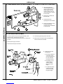
1. Connect the gas valve electrical leads and refit the cover.
2. Check that the gas service cock (E) is ON and that the
boiler thermostat control knob (H) is OFF.
3. Loosen the screw in the burner pressure test point (B) and
connect a gas pressure gauge via a flexible tube.
4. Turn the gas control knob (A) CLOCKWISE until resistance
is felt and then release it..
5. Push in and retain fully depressed the gas control knob (A).
Press and release the piezo unit button (G) repeatedly until
the pilot is seen to light through the sightglass (F).
6. Hold the gas control knob (A) depressed for 15 seconds
after the pilot burner has ignited, then release.
If the pilot burner fails to remain alight at this stage, repeat
the procedure detailed above but wait longer than 15
seconds before releasing the gas control knob (A).
7. Check the appearance of the pilot flame to ensure that it
envelops the tip of the thermocouple and is approximately
25mm (1") long. The pilot flame is factory set and no
adjustment is possible.
8. Switch the boiler thermostat control knob (H ) to position 6
and check that the burner cross-lights smoothly from the
pilot flame.
Note. The pilot burner connection can be tested for gas
soundness. Refer to Frame 24.
9. Test for gas soundness around the boiler gas component
joints, using leak detection fluid.
10. Operate the boiler for 10 minutes to stabilise the burner
temperature. The boiler is pre-set at the factory to its
maximum nominal rating.
11. Immediately check that there is no spillage of combustion
products from the draught diverter outlets by carrying out a
spillage test as detailed in BS.5440:1.
Note. This must be done before any building in.
12. Turn the boiler thermostat knob (H) to OFF.
13. Remove the pressure gauge and tube. Retighten the
screw in the pressure test point, ensuring that a gas-tight
seal is made.
Boiler controls
LEGEND
AGas control knob
BBurner pressure test point
CMain burner pressure adjuster
DInlet pressure test point
EGas service cock
FSightglass
GPiezo ignition button
HBoiler thermostat knob
JOverheat thermostat (optional)
reset button
CF 3/60P shown

20 Mexico Super CF 3/60P - 3/140P - Installation
INSTALLATION
25
GENERAL CHECKS
Make the following checks for correct operation:
1. Turn the boiler thermostat OFF and ON to check that the
main burner is extinguished and relit in response.
2. Check that the programmer, if fitted, and all other system
controls function correctly.
Operate each control separately and check that the main
burner or circulating pump (as the case may be) responds.
3. Flame failure device
Check the operation of the flame failure device in the gas
control valve as follows:
a. Extinguish the pilot flame by closing the gas service
cock and note the time taken for the flame failure
device to shut down - identified by a click within the gas
control valve. This must not be longer than 60 seconds.
b. Open the gas service cock and relight the pilot.
c. Turner the boiler thermostat ON. The burner should
light.
d. Turn the gas control knob to the OFF position - refer to
Frame 23. The main burner and pilot flame should shut
down immediately. Note. A latch in the gas control
valve provides a safety delay period of approximately
30 seconds before the pilot can be relit.
4. Water circulation System
a. With the system HOT, examine all water connections for
soundness.
Thermostat Flow Temperature
Knob Setting oCoF
260 140
366 150
471 160
577 170
682 180
1. Hand the User's Instructions to the householder and
explain his or her responsibilities under the Gas Safety
(Installation and Use) Regulations 1994, amendments
1996 or rules in force.
2. Draw attention to the lighting instruction label affixed to the
inside of the controls door.
3. Explain and demonstrate the lighting and shutting down
procedures, including the function of the TTB downdraught
thermostat.
4. The operation of the boiler and the use and adjustment of
ALL system controls should be fully explained to the
householder, to ensure the greatest possible fuel
economy consistent with household requirements of both
heating and hot water consumption.
Advise the User of the precautions necessary to prevent
damage to the system and to the building, in the event of
the system remaining inoperative during frosty conditions.
b. With the system still hot, turn off the gas, water and
electricity supplies to the boiler and drain down, in
order to complete the flushing process.
c. Refill and vent the system, clear all air locks and again
check for water soundness.
d. Balance the system.
5. Finally, set the controls to the user's requirements, refit the
lower front panel and close the controls door.
Notes.
a. If an optional Programmer Kit is fitted refer to the
separate Programmer Kit Installation Instructions and
User's Instructions.
b. The temperatures quoted below are approximate and
vary between installations.
26
HANDING OVER
After completing the installation and commissioning of the boiler system the installer
should hand over to the householder by the following actions:
5. Explain the function and the use of the boiler thermostat
and external controls.
6. Explain and demonstrate the function of time and
temperature controls, radiator valves etc., for the
economic use of the system.
7. If an optional Programmer Kit is fitted then draw attention
to the Programmer Kit User's Instructions and hand them
to the householder.
8. After installation, commissioning and customer hand-
over instructions please complete the
appliance log book and leave this with the customer.
9. Stress the importance of regular servicing by a CORGI
registered installer and that a comprehensive service
should be carried out AT LEAST ONCE A YEAR.
10. Draw attention to the Emergency Action Notice in the
User's Instructions.
INSTALLATION
Page is loading ...
Page is loading ...
Page is loading ...
Page is loading ...
Page is loading ...
Page is loading ...
Page is loading ...
Page is loading ...
Page is loading ...
Page is loading ...
Page is loading ...
Page is loading ...
Page is loading ...
Page is loading ...
Page is loading ...
Page is loading ...
Page is loading ...
Page is loading ...
Page is loading ...
Page is loading ...
Page is loading ...
Page is loading ...
Page is loading ...
Page is loading ...
-
 1
1
-
 2
2
-
 3
3
-
 4
4
-
 5
5
-
 6
6
-
 7
7
-
 8
8
-
 9
9
-
 10
10
-
 11
11
-
 12
12
-
 13
13
-
 14
14
-
 15
15
-
 16
16
-
 17
17
-
 18
18
-
 19
19
-
 20
20
-
 21
21
-
 22
22
-
 23
23
-
 24
24
-
 25
25
-
 26
26
-
 27
27
-
 28
28
-
 29
29
-
 30
30
-
 31
31
-
 32
32
-
 33
33
-
 34
34
-
 35
35
-
 36
36
-
 37
37
-
 38
38
-
 39
39
-
 40
40
-
 41
41
-
 42
42
-
 43
43
-
 44
44


Ideal Boilers 4134924 Installation And Servicing Manual
- Category
- Water heaters & boilers
- Type
- Installation And Servicing Manual
- This manual is also suitable for
Ask a question and I''ll find the answer in the document
Finding information in a document is now easier with AI
Related papers
-
Ideal Boilers Mexico Super 80 FF Installation And Servicing Manual
-
-
-
-
-
-
-
-
-
Other documents
-
Armitage Shanks S2170 Installation guide
-
IDEAL STANDARD SR021 Installation guide
-
Ideal Mexico Super 3/140 User manual
-
 Light Wave JSJSLW920 User manual
-
 Henrad CC 120 FF User manual
-
IDEAL INDUSTRIES H CXSi 180/H User manual
-
Mamiya Boiler C28 User manual
-
AGA Hilight B50A O45A Gas Boilers Owner's manual
-
-
Baxi Solo 2 RS Quick start guide

