
(English)
DM-SG0006-00
Dealer's Manual
SG-3R40
SG-3R42
SG-3S40
SG-3S42
SL-3S43J
SL-3S58J
SL-3S90
SL-3S91
SM-3S40
Nexus

2
CONTENTS
IMPORTANT NOTICE .............................................................................................. 3
TO ENSURE SAFETY ............................................................................................... 4
INSTALLATION ....................................................................................................... 9
List of tools to be used .................................................................................................................................9
Installation of the lever ...............................................................................................................................9
Installation of the bell crank type hub .....................................................................................................12
ADJUSTMENT ...................................................................................................... 21
Adjusting the bell crank ............................................................................................................................21
MAINTENANCE .................................................................................................... 24
Replacement of the shifting cable ............................................................................................................24
Oil maintenance of the internal assembly ................................................................................................28

3
IMPORTANT NOTICE
IMPORTANT NOTICE
•
This dealer’s manual is intended primarily for use by professional bicycle mechanics.
Users who are not professionally trained for bicycle assembly should not attempt to install the components themselves using the dealer’s manuals.
If any part of the information on the manual is unclear to you, do not proceed with the installation. Instead, contact your place of purchase or a local
bicycle dealer for their assistance.
•
Make sure to read all instruction manuals included with the product.
•
Do not disassemble or modify the product other than as stated in the information contained in this dealer’s manual.
•
All dealer’s manuals and instruction manuals can be viewed on-line on our website (http://si.shimano.com).
•
Please observe the appropriate rules and regulations of the country, state or region in which you conduct your business as a dealer.
For safety, be sure to read this dealer’s manual thoroughly before use, and follow it for correct use.
The following instructions must be observed at all times in order to prevent personal injury and physical damage to equipment and surroundings.
The instructions are classified according to the degree of danger or damage which may occur if the product is used incorrectly.
DANGER
Failure to follow the instructions will result in death or serious injury.
WARNING
Failure to follow the instructions could result in death or serious injury.
CAUTION
Failure to follow the instructions could cause personal injury or physical damage to equipment and surroundings.

4
TO ENSURE SAFETY
TO ENSURE SAFETY
WARNING
•
When installing components, be sure to follow the instructions that are given in the instruction manuals.
It is recommended that you use only genuine Shimano parts. If parts such as bolts and nuts become loose or damaged, the bicycle may suddenly fall
over, which may cause serious injury.
In addition, if adjustments are not carried out correctly, problems may occur, and the bicycle may suddenly fall over, which may cause serious injury.
•
Be sure to wear safety glasses or goggles to protect your eyes while performing maintenance tasks such as replacing parts.
•
After reading the dealer's manual thoroughly, keep it in a safe place for later reference.
Be sure to also inform users of the following:
•
Each bicycle may handle slightly differently depending on the model.
Therefore, be sure to learn the proper braking technique (including brake lever pressure and bicycle control characteristics) and operation of your
bicycle. Improper use of your bicycle's brake system may result in loss of control, the bicycle falling over, and severe injury. For proper operation,
consult your professional bicycle dealer or the bicycle's instruction manual. It is also important to practice riding as well as braking operation, etc.
•
The brake levers are equipped with a mode switching mechanism to make them compatible with cantilever brakes and roller brakes or V-BRAKE
brakes with power modulator.
If an incorrect mode is selected it may cause either excessive or insuffi cient braking force, which is very dangerous.
Be sure to select the mode in accordance with the instructions given in the table below.
Mode position Applicable brake
C : Mode position for compatibility with cantilever
brakes
R : Mode position for compatibility with roller
brakes
C R
V
V
C R
V
V
C R
C/R position
•
Cantilever brakes
•
Roller brakes
V : Mode position for compatibility with V-BRAKE
brakes with power modulator
C R
V
V
C R
V
V position
•
V-BRAKE brakes with power
modulator
Use the brake levers with mode switching mechanism in the combinations given above.
•
When installing components, be sure to follow the instructions that are given in the instruction manuals. It is recommended that you use only genuine
Shimano parts. If parts such as bolts and nuts become loose or damaged, the bicycle may suddenly fall over, which may cause serious injury.
•
Check that the wheels are fastened securely before riding the bicycle. If the wheels are loose in any way, they may come off the bicycle and serious
injury may result.

5
TO ENSURE SAFETY
For Installation to the Bicycle, and Maintenance:
•
When securing the brake arm to the frame, be sure to use an arm clip that matches the size of the chainstay, and securely tighten it with the clip bolt
and clip nut to the specified tightening torque. Use a lock nut with a nylon insert (self-locking nut) for the clip nut. It is recommended that Shimano
made clip bolts, clip nuts, and arm clips be used. Use an arm clip that matches the chainstay.
If the clip nut comes off the brake arm, or if the clip bolt or arm clip becomes damaged, the brake arm may rotate on the chainstay and cause the
handlebars to jerk suddenly, or the bicycle wheel may lock and the bicycle fall over, causing serious injury.
•
When installing the hub to the frame, be sure to install the designated non-turn washer, and securely tighten the hub nut to the specified torque. If a
non-turn washer is not installed, or if the hub nut is not tightened sufficiently, the non-turn washer may fall out, which could cause the hub axle to
rotate, resulting in the handlebars being accidentally pulled by the shifting cable and leading to an extremely serious accident.
•
When installing components, be sure to follow the instructions that are given in the instruction manuals. It is recommended that you use only genuine
Shimano parts. If parts such as bolts and nuts become loose or the product is damaged, the bicycle may suddenly fall over, which may cause injury.
•
When using a reversed fork end, use a chain adjuster to remove excess slack from the chain.
CAUTION
Be sure to also inform users of the following:
•
Be sure to shift the shifting lever one gear at a time. During shifting, reduce the force being applied to the pedals. If you try to force operation of the
shifting lever or perform multi-shifting while the pedals are being turned strongly, your feet may come off the pedals and the bicycle may fall over,
which could result in serious injury.
Operating the shifting lever to multi-shift to a light gear may also cause the outer casing to spring out of the shifting lever.
This does not affect the capabilities of the shifting lever because the outer casing returns to the original position after shifting.
•
When this product is used with ST-3S35, SB-3S20-J, SB-3S25-J, or SL-3S10 (domestic model), the indicator display is reversed.
•
Never place your foot on the bell crank. Otherwise, gear shifting may not function properly.
•
The Shimano inter-M brake system cannot be used with mountain bikes. Even for other types of bicycles, continuous application of the brakes when
riding down long slopes will cause the internal brake parts to become very hot, weakening braking performance; it may also reduce the amount of
grease inside the brake, leading to problems such as sudden braking.
•
If any of the following occur while using the brakes, stop riding immediately and ask the place of purchase to carry out inspection and repairs.
1) If an abnormal noise is heard when the brakes are applied
2) If the braking force is abnormally strong
3) If the braking force is abnormally weak
In the case of 1) and 2), the cause might be not enough brake grease, so ask the place of purchase to grease the mechanism with special roller brake
grease.
•
In order to get the best performance from the Shimano inter-M brake, be sure to use Shimano brake cables and brake levers as a set.
(The amount of movement of the inner cable must be 14.5 mm or more when the brake lever is depressed. If it is less than 14.5 mm, braking
performance will suffer, and the brakes may fail to work.)
•
Check that the brake arm is securely fastened to the chainstay by the arm clip. If it is not installed correctly, braking performance will suffer.

6
TO ENSURE SAFETY
•
If the brake is used frequently, the area around the brake may become hot. Do not touch the area around the brake for at least 30 minutes after
riding the bicycle.
Area around the brake
•
If the brake cable becomes rusted, braking performance will suffer. If this happens, replace the brake cable with a genuine Shimano brake cable and
re-check the braking performance.
•
The brake unit of the inter-M brake should never be disassembled. If it is disassembled, it will no longer work properly.
•
Do not apply grease to the roller clutch. Greasing the roller clutch excessively may cause it to slip.

7
TO ENSURE SAFETY
NOTE
Be sure to also inform users of the following:
•
It is possible to shift gears while pedaling lightly, but on rare occasions the pawls and ratchet inside the hub may produce some noise afterwards as
part of normal gear shifting operation.
•
During travel, stopping the pedals makes it easier to shift gears.
•
The inter-M brake is different from conventional band brakes in that the inside of the brake drum is filled with grease, causing the turning of the tire
to be slightly heavier than usual. (Particularly in cold weather.)
•
If the wheel becomes stiff and difficult to turn, lubricate it.
•
For carrying out maintenance, the use of Shimano internal geared hub grease or a lubrication kit is recommended. If Shimano grease is not used,
problems such as a malfunction in gear shifting may occur.
•
The internal geared hub is not completely waterproof. Avoid using the hub in places where water might get inside it or using high-pressure water to
clean the hub, otherwise the internal mechanism may rust.
For Installation to the Bicycle, and Maintenance:
•
You should periodically wash the sprockets in a neutral detergent and then lubricate them again. In addition, cleaning the chain with a neutral
detergent and lubricating it can be an effective way of extending the useful life of the sprockets and chain.
•
If the chain keeps coming off the chainrings during use, replace the chainrings and chain.
•
Use a wheel with 3x or 4x spoke lacing. Wheels with radial lacing cannot be used. Otherwise, the spokes or the wheel may be damaged, or noise may
occur when braking.
•
Do not lubricate the internal parts of the hub. Otherwise, grease will flow out.
•
To maintain the product in good working order, it is recommended to have the place of purchase or nearest Pro shop carry out maintenance such as
lubrication of the internal parts about once every two years from the first time of use (once about every 5,000 km if the bicycle is used very
frequently). Also, for carrying out maintenance, the use of Shimano internal geared hub grease or a lubrication kit is recommended. If Shimano grease
or a Shimano lubrication kit is not used, problems such as a malfunction in gear shifting may occur.
•
Products are not guaranteed against natural wear and deterioration from normal use and aging.
•
For maximum performance we highly recommend Shimano lubricants and maintenance products.
The actual product may differ from the illustration because this manual is intended chiefly to explain the procedures for using
the product.

INSTALLATION

To be continued on next page
9
INSTALLATION
List of tools to be used
INSTALLATION
List of tools to be used
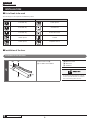
The following tools are required to assemble the product.
Tool Tool
3 mm Allen key 17 mm spanner
4 mm Allen key Screwdriver #2
5 mm Allen key TL-CT12 cable cutter
10 mm spanner
TL-LR10
15 mm spanner Adjustable wrench
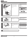
Installation of the lever
Installation of the shift lever
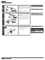
1
(B)(A)
(C)
(a)
Install the brake lever (B).
(a) Use Φ22.2 mm handlebars.
(A) Brake lever band
(B) Brake lever
(C) Handlebar
Use a brake lever with a thickness of 4.3 mm
or lower to prevent the brake lever and shift
lever from interfering with each other.

10
INSTALLATION
Installation of the lever
2
(D)
(b)
Install the shift lever (D).
(b) The straight section of the
handlebar must be 158 mm or
longer.
The shift lever is installed to this
straight section.
(D) Shift lever
< In the case of SL-3S58J >
Leave a gap of 20 mm or more between the
brake lever and the shift lever.
20 mm
or longer
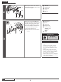
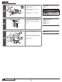
3
(E)
(F)
Install the half grip (E).
Leave a 0.5 mm gap between the shift
lever and the half grip (F).
(E) Half grip
(F) Gap between the shift lever and
the half grip
4
(G)
Tighten the shift lever.
(G) Fixing bolt
Tightening torque
2 - 2.5 N·m
{18 - 21 in. lbs.}

11
INSTALLATION
Installation of the lever
Installation of the piano touch lever
1
(a)
(B)(A)
Mount the clamp band (B) to the
handlebars.
(a) Use Φ22.2 mm handlebars.
(A) Piano touch lever
(B) Clamp band
2
(D)(C)
Secure the clamp band to the handlebars
with the fixing screw (D) and fixing nut
(C).
(C) Fixing nut
(D) Fixing screw
Tightening torque
2.5 - 3 N·m
{22 - 26 in. lbs.}
NOTE
Observe the correct orientation of the
fixing nut.

12
INSTALLATION
Installation of the bell crank type hub
Installation of the bell crank type hub
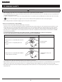
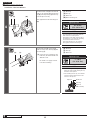
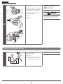
Installation of the sprocket to the hub
(a)
(A)
(B)
(C)
(D)
(E)
Place the right-hand waterproof cap B
(C) onto the driver (D) on the right side
of the hub body.
Next, install the sprocket (B) and secure
it in place with the snap ring (A).
(a) Note the direction
(A) Snap ring
(B) Sprocket
(C) Right-hand waterproof cap B
(D) Driver
(E) Right-hand waterproof cap A

To be continued on next page
13
INSTALLATION
Installation of the bell crank type hub
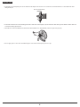
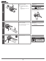
Installation of the bell crank
(A)
(C)
(D)
(E)
(B)
Install the hub to the frame.
The installation procedure differs
depending on the width (A).
Follow the instructions below for
installation.
(A) Width A
(B) Lock nut
(C) Stand
(D) Fork end
(E) Chain tensioner
The chain adjuster to be attached to the right
side should have a fl at-sided hole.
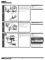
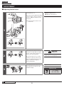
10 mm
< When the width A is between 5.5 and 10.5 mm >
1
(F)
(G)
Push the non-turn part of the bracket (F)
fi rmly into the oval hole in the stand (G)
or the fork end.
(F) Non-turn part of the bracket
(G) Oval hole in the stand
< When the width A is less than 5.5 mm >
1
(a)
(H)
Push the protrusion of the washer with a
4 mm protrusion (H) into the fork end
and the non-turn part of the bracket
fi rmly into the indentation in the washer.
(a) Added
(H) Washer with a 4 mm protrusion
NOTE
For belt-driven bicycles, make sure that the
bell crank is not in contact with the screw on
the frame joint. If they are in contact with
each other, attach the washer with a 4 mm
protrusion.
< When the width A is 10.6 mm or more >
1
Use a hub with a 191.8 mm long axle.

To be continued on next page
14
INSTALLATION
Installation of the bell crank type hub
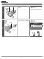
2
(I)
(M)
(L)
(K)(J)
Mount the parts in the order shown in
the illustration and temporarily fix them
with the hub nut (M).
(I) Bell crank
(J) Mudguard stay
(K) Carrier stay
(L) Washer
(M) Hub nut
3
0
(N)
(O)
(P)
(Q)
(S)(R)(b)
Attach the non-turn washer (R) to the
left side of the hub axle as shown in the
illustration and temporarily fix it with
the left hub nut (N), making sure that
the non-turn washer is attached at the
correct position with its protrusion
oriented in the right direction.
(b) The side with notches should face
inward.
(N) Left hub nut
(O) Washer
(P) Carrier stay
(Q) Mudguard stay
(R) Non-turn washer
Thickness: 4 mm
Color: Black
Mark: 0
(S) Stand
Tightening torque
30 - 45 N·m
{263 - 393 in. lbs.}
NOTE
•
The protrusion should be on the fork end
side.
•
Install the non-turn washer so that the
protrusion fits securely in the fork end
groove at the front and back sides of the
hub axle.
•
When installing a stand to the hub axle,
place the non-turn washer onto the stand
from the outer side so that the protrusion
fits into the groove in the stand.
•
When installing a part such as a mudguard
stay to the hub axle, place it onto the outer
side of the non-turn washer.

To be continued on next page
15
INSTALLATION
Installation of the bell crank type hub
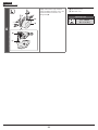
< Installation of the inter-M brake >
4
(V)
(W)(T) (U)
Install the brake arm (V) of the inter-M
brake to the chainstay (T) using the arm
clip (U) and temporarily tighten the clip
bolt and clip nut loosely.
Then, tighten the brake unit fi xing nut
(W).
(T) Chainstay
(U) Arm clip
(V) Brake arm
(W) Brake unit fi xing nut
Tightening torque
20 - 25 N·m
{175 - 218 in. lbs.}
NOTE
If it is impossible to temporarily attach the
brake arm to the chainstay due to
misalignment of the brake arm as shown in
the illustration, loosen the brake unit fi xing
nut and turn the brake arm before
temporarily attaching it to the chainstay.
Then, tighten the brake unit fi xing nut.
5
(Z)
(Y)
(c)
(X)
Fix the brake arm (Z) of the inter-M
brake securely to the chainstay (X) with
the arm clip (Y).
(c) If excessive force is applied to the
brake arm, the wheel will become
diffi cult to turn.
Be careful not to apply excessive
force when installing.
(X) Chainstay
(Y) Arm clip
(Z) Brake arm
Tightening torque
2 - 3 N·m
{18 - 26 in. lbs.}
NOTE
•
When installing the arm clip, securely
tighten the clip bolt while holding the clip
nut with a 10 mm spanner.
•
After installing the arm clip, check that the
clip bolt protrudes about 4 mm from the
end face of the clip nut.
About 4 mm
Arm clip
Clip bolt
(M6 × 16 mm)
Brake armClip nut

To be continued on next page
16
INSTALLATION
Installation of the bell crank type hub
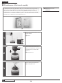
< Installation of the brake cable >
6
(d)
(AC)
(AA) (AB)
Place the cable adjustment bolt (AA) so
that it is 15 – 17 mm from the end of the
brake arm (AB), and then pass the inner
cable through the cable adjustment bolt
of the brake arm and then through the
hole in the inner cable fi xing bolt (AC).
(d) Should be 15 – 17 mm
(AA) Cable adjustment bolt
(AB) Brake arm
(AC) Hole in the inner cable fi xing bolt
7
(e)
(AD)
Check that both ends of the outer casing
are securely inserted into the cable
adjustment bolts (AD) of both the brake
lever and brake arm.
(e) Both ends of the outer casing
should be securely inserted.
(AD) Cable adjustment bolt
8
(f)
(AE)
(AG)
(AF)
Pull the link (AE) back until it stops.
Then, while pulling the inner cable (AG)
to apply the full amount of tension to
the cable, tighten the inner cable fi xing
nut (AF).
(AE) Link
(AF) Inner cable fi xing nut
(AG) Inner cable
Tightening torque
6 - 8 N·m
{53 - 69 in. lbs.}
NOTE
Set the inner cable so that it passes
below the link as shown in illustration
(f).

To be continued on next page
17
INSTALLATION
Installation of the bell crank type hub
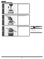
< Adjustment of the brake cable >
9
(g)
After checking that the wheel does not
easily turn while the brake cable is being
pulled, depress the brake lever about 10
times as far as the grip in order to run in
the brake cable.
(g) Depress about 10 times
NOTE
If the brake cable is not run in, it will need to
be adjusted again after only a short period of
use.
10
(h)
(AH)
Turn the cable adjustment bolt (AH) so
that there is about 15 mm of play (h) in
the brake lever.
*
The amount of brake lever play is the
distance from the position where the
brake lever is not operated to the
position where a force is felt suddenly
when the brake lever is pulled.
(AH) Cable adjustment bolt
11
(AI)
After depressing the brake lever to check
the braking performance, secure the
cable adjustment bolt with the cable
adjustment nut (AI).
(AI) Cable adjustment nut
Tightening torque
1 - 2 N·m
{9 - 17 in. lbs.}

To be continued on next page
18
INSTALLATION
Installation of the bell crank type hub
12
(i)
(i)
(i)
(AK)
(AJ)
When tightening the hub nut, pull the
link (AK) towards you.
Be careful not to deform the bracket
with a wrench (AJ).
(i) Be careful not to hit with the
wrench
(AJ) Wrench
(AK) Link
Tightening torque
30 - 45 N·m
{263 - 393 in. lbs.}
13
(AO)
(AM)(AL)
(AN)
(j)
After tightening the hub nut (AO), check
that the hub axle on the right side
protrudes from the end face of the hub
nut (j).
(AL) Mudguard stay
(AM) Carrier stay
(AN) Washer
(AO) Hub nut
14
(k)
(AP)
Insert the push rod (AP) into the hub
axle.
The push rod should protrude about 14
mm from the end face of the hub axle.
(k) About 14 mm
(AP) Push rod

19
INSTALLATION
Installation of the bell crank type hub
15
(AQ)
(AR)
(AS)
(l)
(m)
Set the lever to 1.
With the cable adjustment bolt (AQ) of
the bell crank tightened, pass the inner
cable through the cable adjustment bolt.
Hook the inner cable drum (AS) into the
groove in the link (AR).
(l) Hook
(m) Tighten
(AQ) Cable adjustment bolt
(AR) Groove in the link
(AS) Inner cable drum
For information on how to adjust the SM-3S40
bell crank, refer to the instruction manual
supplied with the shifting lever.
Securing the shifting cable to the frame
(a)
(b)
(A)
Secure the cable to the frame with the
outer casing bands (A).
(a) 20 - 25 cm
(b) Slacken the cable to prevent strain
from being placed on the cable
when turning the handlebars.
(A) Outer casing bands

ADJUSTMENT
Page is loading ...
Page is loading ...
Page is loading ...
Page is loading ...
Page is loading ...
Page is loading ...
Page is loading ...
Page is loading ...
Page is loading ...
Page is loading ...
-
 1
1
-
 2
2
-
 3
3
-
 4
4
-
 5
5
-
 6
6
-
 7
7
-
 8
8
-
 9
9
-
 10
10
-
 11
11
-
 12
12
-
 13
13
-
 14
14
-
 15
15
-
 16
16
-
 17
17
-
 18
18
-
 19
19
-
 20
20
-
 21
21
-
 22
22
-
 23
23
-
 24
24
-
 25
25
-
 26
26
-
 27
27
-
 28
28
-
 29
29
-
 30
30


Ask a question and I''ll find the answer in the document
Finding information in a document is now easier with AI
Related papers
-
Shimano FC-M100 Exploded View
-
-
-
-
Shimano BL-M820 Exploded View
-
Shimano SG-3S42 User manual
-
Shimano SG-S7001-11 User manual
-
Shimano BR-IM35-RF Service Instructions
-
-
Shimano SG-8R60 User manual
Other documents
-
Delta HL6700R User manual
-
Centurion ROAD BIKE ISO 4210-2 User manual
-
BMW Mountain Bike Enduro Owner's manual
-
SCOTT Time Trial Machine Owner's manual
-
 Merida Bike User manual
-
Diamondback SHEPPARD CYCLES Owner's manual
-
Nexus SW-NX30 Service Instructions
-
Hasbro Busy Gears-Super Set Operating instructions
-
-
sks BLUEMELS User manual
