Page is loading ...

SERVICE MANUAL
Projection Television
56HM66 Rev.1
This model is classified as a green product (*1), as indicated by the underlined serial number.
This Service Manual describes replacement parts for the green product. When repairing this
green product, use the part(s) described in this manual and lead-free solder (*2).
For (*1) and (*2), refer to GREEN PRODUCT PROCUREMENT and LEAD-FREE
SOLDER.
© TOSHIBA CORPORATION 2008
For Technical Bulletins, Technical Tips, or other information regarding the
service of this model, visit the Toshiba America Consumer Products National
Service Division website at:
www7.toshiba.com

IMPORTANT NOTICE
WARNING: Do not modify or alter the information or data provided herein without prior written consent by Toshiba.
Toshiba shall not be liable to anybody for any damages, losses, expenses or costs, if any, incurred in connection with or
as a result of such modification or alteration.
THE INFORMATION OR DATA HEREIN SHALL BE PROVIDED "AS IS" WITHOUT ANY WARRANTY OF ANY KIND, EITHER
EXPRESS OR IMPLIED WARRANTY OF MERCHANTABILITY AND FITNESS FOR A PARTICULAR PURPOSE.
Toshiba shall not be liable for any damages, losses, expenses or costs, if any, incurred in connection with or as a result of
use of any information or data provided herein.
GREEN PRODUCT PROCUREMENT
The EC is actively promoting the WEEE & RoHS Directives that define standards for recycling and reuse of Waste Electrical and
Electronic Equipment and for the Restriction of the use of certain Hazardous Substances. From July 1, 2006, the RoHS Directive will
prohibit any marketing of new products containing the restricted substances.
Increasing attention is given to issues related to the global environmental. Toshiba Corporation recognizes environmental protection
as a key management tasks, and is doing its utmost to enhance and improve the quality and scope of its environmental activities. In
line with this, Toshiba proactively promotes Green Procurement, and seeks to purchase and use products, parts and materials that
have low environmental impacts.
Green procurement of parts is not only confined to manufacture. The same green parts used in manufacture must also be used as
replacement parts.
LEAD-FREE SOLDER
WARNING: This product is manufactured using lead-free solder as a part of a movement within the consumer products industry at
large to be environmentally responsible. Lead-free solder must be used in the servicing and repair of this product.
The melting temperature of lead-free solder is higher than that of leaded solder by 86ºF to 104ºF (30ºC to 40ºC). Use of a soldering
iron designed for lead-based solders to repair product made with lead-free solder may result in damage to the component and or
PCB being soldered. Great care should be made to ensure high-quality soldering when servicing this product especially when
soldering large components, through-hole pins, and on PCBs as the level of heat required to melt lead-free solder is high.
SAFETY INSTRUCTION
WARNING: Before servicing this chassis, read the "Safety Precaution" and "Product Safety Notice" instructions below.
Safety Precaution
WARNING: Servicing should not be attempted by anyone unfamiliar with the necessary precautions on this receiver. The following
are the necessary precautions to be observed before servicing this chassis.
1. An isolation transformer should be connected in the power line between the receiver and the AC line before any service is
performed on the receiver.
2. Always disconnect the power plug before any disassembling of the product. It may result in electrical shock.
3. When replacing a chassis in the cabinet, always be certain that all the protective devices are put back in place, such as
nonmetallic control knobs, insulating covers, shields, isolation resistor-capacitor network, etc.
4. Always keep tools, product components, etc. away from children as these items may cause injury.
5. Depending on the model, use an isolation transformer or wear suitable gloves when servicing with the power on.
Disconnect the power plug to avoid electrical shock when replacing parts. In some cases, alternating current is also
impressed in the chassis, so electrical shock is possible if the chassis is contacted with the power on.
6. Always use the replacement parts specified for the particular model when making repairs. The parts used in products
require special safety characteristics such as inflammability; voltage resistance, etc. therefore, use only replacement parts
1

that have these same characteristics. Use only the specified parts when the mark is indicated in the circuit diagram or
parts list.
7. Part mounting and wire routing should be the same as that used originally. For safety purposes, insulating materials such as
isolation tubes or tape are sometimes used and printed circuit boards are sometimes mounted floating. Also make sure that
wiring is routed and clamped to avoid parts that generate heat or use high voltage. Always follow the manufactures wiring
routes / dressings.
8. Always ensure that all internal wirings are in accordance before re-assembling the external casing after a repair is
completed. Do not allow internal wiring to be pinched by cabinets, panels, etc. Any error in reassembly or wiring can result
in electrical leakage, flame, etc., and may be hazardous.
9. NEVER remodel the product in any way. Remodeling can result in improper operation, malfunction, electrical leakage, or
flame, which may be hazardous.
10. Always perform an AC leakage current check on the exposed metallic parts of the cabinet such as antennas, terminals,
screw heads, metal overlays, control shafts, etc. to be sure that the set is safe to operate without any danger of electrical
shock before returning the set to the customer.
11. To check leakage current: (After completing the work, measure the leakage current to prevent an electrical shock.)
• Plug the AC line cord directly into a 120V AC outlet. Do not use an isolation transformer for this check.
• Use an AC voltmeter having 5000 ohms per volt or more sensitivity in the following manner.
Connect a 1500 ohm 10 watt resistor, paralleled by a 0.15 µF, AC type capacitor, between a known good earth ground (water pipe,
conduit, etc.) and the exposed metallic parts, one at a time. Measure the AC voltage across the combination of 1500 ohm resistor
and 0.15 µF capacitor. Reverse the AC plug at the AC outlet and repeat AC voltage measurements for each exposed metallic part.
Voltage measured must not exceed 0.3 volts rms. This corresponds to 0.2 milliamps AC. Any value exceeding this limit constitutes a
potential shock hazard and must be corrected immediately.
Product Safety Notice
Many electrical and mechanical parts in this chassis have special safety-related characteristics. These characteristics are often
overlooked in a visual inspection. The protection afforded by them cannot necessarily be obtained by using replacement
components rated for higher voltage, wattage, etc. Replacement parts which have these special safety characteristics are identified
in this manual and its supplements. Electrical components having such features are identified by the international hazard symbols
on the schematic diagram and the parts list. Before replacing any of these components, read the parts list in this manual carefully.
The use of substitute replacement parts which do not have the same safety as specified in the parts list may create electrical shock,
fire, or other hazards.
2

Entering Service Mode
1. Set VOLUME to minimum and press MUTE button twice on the remote
control.
↓
2. Press MUTE button again and hold button down.
↓
Service Mode display
3. While holding the MUTE button, press MENU button on TV set.
Selecting the Adjusting Item
Every pressing of CH
or button in the service mode changes the adjustment items.
Adjusting the Data
Pressing of VOLUME
or button will change the value of data in the range from 00H to FFH. The variable range depends on
the adjusting item.
Exiting Service Mode
Pressing POWER button to turn off the TV once.
3

LED BLINK CODES
The yellow, blue, and red/green LED lights on the TV (at the bottom center of the TV) indicate the TV's status, as described below:
Note: If the TV loses A/C power (e.g., a power outage occurs or the power cord is unplugged), when power is restored, the yellow
LED will blink while the TV is booting until the remote control is usable. This is normal and is not a sign of malfunction.
50HM66/56HM66
BLUE YELLOW RED/GREEN VOICE
MODE POWER LAMP TIMER ANNOUNCEMENT
POWER ON
ON
POWER OFF (Standby w/ Quick
Restart OFF)
IN LPS (Standby w/ Quick
restart ON)
Blinking
Waiting to re-light the lamp
ON Blinking
Lamp won’t light
ON Blinking
YES
Open Lamp door
ON
YES
Fan Stop Detection (Light
Engine)
Blinking
YES
Fan Stop Detection (POD)
ON
Blinking
YES
Fan Stop Detection (Ballast)
ON
Blinking
YES
IIC BUS Error
Slow
blinking
YES
Color wheel stop
Fast
blinking
Blinking
YES
Abnormal temperature in
Thermo Sensor
Fast
blinking Blinking Blinking
YES
Seine Booting
3 Blinks
SLEEP TIMER
ON
4

Replacing the Lamp Unit
WARNING: RISK OF ELECTRIC SHOCK! TO REDUCE THE RISK OF ELECTRIC SHOCK, NEVER REMOVE TV COVERS,
EXCEPT AS SPECIFIED HEREIN. REFER ALL SERVICING NOT SPECIFIED IN THIS MANUAL TO QUALIFIED SERVICE
PERSONNEL. Failure to follow this WARNING may result in death or serious injury.
The light source for this TV is a mercury lamp with internal atmospheric pressure that increases during use. The lamp has a limited
service life that varies depending on product use and user settings.
As is generally the case with all projection TVs that use projection lamps as a light source, the brightness of the lamp in this TV may
vary somewhat over the expected service life and will generally decrease over time. Because of the many variables that can affect
the useful service life of the lamp, your experience may vary from other users.
If you use the lamp beyond its service life you may notice a reduction in the colors and/or brightness of the picture. The strength of
the quartz glass in the lamp will be reduced and the lamp may rupture (often making a loud noise when this happens). If the lamp
ruptures, the TV will not operate until the lamp unit is replaced.
CAUTION: Always handle the lamp unit with care. The lamp unit in this TV was designed for safe replacement by consumers;
however, if the lamp unit is subjected to intentional abuse (such as excessive mechanical abuse or handling by children or pets), the
unit may break, exposing sharp edges or pinch points.
WARNING: RISK OF ELECTRIC SHOCK! TO REDUCE THE RISK OF ELECTRIC SHOCK, NEVER REMOVE TV COVERS,
EXCEPT AS SPECIFIED HEREIN. REFER ALL SERVICING NOT SPECIFIED IN THIS MANUAL TO QUALIFIED SERVICE
PERSONNEL. Failure to follow this WARNING may result in death or serious injury.
1. Turn off the TV and unplug the power cord.
WARNING: Eye damage may result from directly viewing the light produced by this lamp. Always turn off the TV and unplug
the power cord before opening the lamp unit door.
CAUTION! HOT SURFACE! Touching the lamp before it has cooled will result in severe burns. ALLOW THE LAMP TO
COOL FOR AT LEAST ONE (1) HOUR BEFORE REPLACING IT.
2. Using a manual, slotted screwdriver, loosen the screw securing the lamp door and remove the door.
3. Using a manual Phillips screwdriver, loosen the two screws on the lamp unit.
5

WARNING: RISK OF ELECTRIC SHOCK! The lamp unit door is provided with an interlock to reduce the risk of electric
shock and excessive ultraviolet radiation. Never defeat its purpose or attempt to service without removing the lamp
unit door completely. Failure to follow this WARNING may result in death or serious injury.
4. Grasp the lamp unit handle and gently pull the lamp unit straight out of the TV. Set the old lamp unit aside (-> "Disposing of
the used lamp unit" on Owners’ Manual). NOTE: Wear soft, lint-free gloves when replacing the lamp unit.
5. Carefully insert the new lamp unit straight into the TV until it is fully seated.
NOTE: Never subject the lamp unit to excessive shock. Never touch the lamp unit glass or otherwise get it dirty. Doing so may
affect the image quality and reduce the service life of the lamp. See "Cleaning the lamp unit glass" below.
CLEANING THE LAMP UNIT GLASS
If you accidentally touch the lamp unit glass or otherwise get it dirty, wipe it with a lint-free lens cleaning cloth (such as a cloth for
cleaning camera lenses or eyeglasses).
CAUTION: NEVER clean a hot lamp with any type of flammable liquid or aerosol cleaning agent. Many ordinary cleaning
agents (such as glass cleaners) contain chemicals that may be flammable at certain temperatures. If the lamp unit is not allowed to
cool for at least one (1) hour, such chemicals may ignite.
6. Using a manual Phillips screwdriver, tighten the two lamp unit screws. NOTE: Hand-tighten only. Do not use an electric
screwdriver. Make sure the lamp unit and screws are installed securely. Otherwise, the TV may no turn on and the
lamp life may be shortened.
6

7. Reattach the lamp unit door, making sure to insert the hooks on the left side of the door inside the opening in the TV cabinet.
8. Replace the door screw and tighten using a manual screwdriver. NOTE: Make sure the lamp unit door is installed
securely; otherwise, the TV may not turn on.
9. Plug in the power cord and turn on the TV. After the initial warm-up period (which may take several seconds for full picture
brightness), the TV should operate normally. If any of the following conditions exist, turn off the TV, unplug the power cord,
and repeat steps 1-9 to ensure that the lamp unit and lamp unit door are installed correctly:
• No picture
• Dark picture
• TV will not turn on
NOTE: If, after repeating steps 1-9, the problem still exists:
• In the U.S., call TACP Consumer Solutions at 1-800-631-3811.
• In Canada, locate the nearest Toshiba authorized service depot by directing your web browser to www.toshiba.ca;
click "Home Entertainment", and then click "Support".
Disposing of the Used Lamp Unit
CAUTION: Always handle the lamp unit with care. The lamp unit in this TV was designed for safe replacement by consumers;
however, if the lamp unit is subjected to intentional or accidental abuse (such as excessive mechanical abuse or handling by
children or pets), the unit may break, exposing sharp edges or pinch points.
• Place the used lamp unit in the empty box from the new unit.
• Keep the lamp unit out of reach of children and pets.
• Dispose of the used lamp unit by the approved method for your area.
NOTE: The lamp unit contains mercury. Disposal of mercury may be regulated due to environmental considerations. For disposal
or recycling information, contact your local authorities or the Electronic Industries Alliance (www.eiae.org).
7

_
____________________________________________________________________________
_
2007 Toshiba America Consumer Products, LLC. Page 10 of 12
SMART2006001_Version2.2
Front Bezel Removal
50HM66, 50HMX96, 56HM16, 56HM66, 56HMX96
1. Remove 7 Screws from cabinet Back
2. Remove Front Plate
3. Remove 2 Screws
4. Pull front Bezel up then out
8

LIGHT ENGINE REPLACEMENT
1. Remove the back cover.
2. Remove the lamp cover by removing screws 1, 2, and 3.
3. Remove the LVDS and POWER cables.
4. Unfasten the thermostat lead wires. (Leave the thermostat Breaker.)
9

5. Remove the door SW unit by unscrewing as shown below.
6. Disconnect the ballast cable and remove the ballast unit from the retaining clips 1 - 4.
7. Remove the light engine. Reassemble the light engine by following steps 1 – 7 in reverse.
Lamp Fan Replacement
1. Remove screws 1, 2, and 3 securing the lamp fan cover and remove the lamp fan cover.
10

2. Remove the Ballast Fan cable (1) and Lamp Fan cable (2).
3. Remove the 2 screws securing the Lamp fan and remove the lamp fan.
4. Remove the 4 rubber corners from the old lamp fan and place them on the new lamp fan.
5. Assemble the new fan to the light engine by following steps 1 – 4 in reverse.
11

DMD Fan Replacement
1. Remove the DMD Fan cable.
2. Remove the DMD Fan casing by removing screws 1, 2, and 3.
3. Remove the 2 screws securing the LVDS connector.
12

4. Remove the DMD shield case by removing screws 1 and 2.
5. Remove the DMD Fan by removing screws 1 and 2.
6. Assemble the new DMD fan by following steps 1 – 5 in reverse.
Ballast Fan Replacement
1. Remove the retaining pins from the fan.
13

2. Replace the Ballast Fan.
3. Fix the Ballast Fan with two pins.
Thermostat Breaker Replacement
1. Disconnect the thermostat lead wires.
14

2. Replace the Thermostat Breaker by removing the retaining screw.
(Thermostat Breaker is secured by 2 screws in some production units.)
3. Reconnect the thermostat lead wires.
15

______________________________________________________________________________
2007 Toshiba America Consumer Products, LLC.
SMART2006001_Version2.2
Lamp fails to light
Power the Set On
using the power
button
Is a Power
Relay Click
heard?
Repair Chassis Power
Supply and/or System
Control
No
Do any of the
LED’s light or
blink?
No
Yes
Select LED Blink Sequence after
pressing the Power Button
Yes
YELLOW - 1/2 second blink
BLUE - Solid
RED - Off
YELLOW - Solid
BLUE - Off
RED - Off
YELLOW - Solid
BLUE - Off
RED - .5 second blink
YELLOW - Off
BLUE - Off
RED - .5 second blink
YELLOW - Off
BLUE - 1 second blink
RED - Off
YELLOW - Off
BLUE - Solid
GREEN - .5 second blinks
UNKNOWN Sequence or No Sequence
Trying to Light the Lamp (Chassis will try
this cycle about 8 times)
Inspect Lamp
Assy / Substitute
Lamp
Lamp
Defective?
No
Did Lamp Light
within 8 Cycles?
No
Yes
Yes
Lamp door is OPEN. Check Lamp Door Switch
and Cables between the Switch and Chassis
One of the Optical Engine Fans Has Stopped
BUS Line Error. Refer to Chart 4
POD Fan Has Stopped
(Lamp will still light but has error Indication on
Screen)
Unit is Working OK
Replace LAMP
Go To Chart 2
Troubleshooting Flowchart 2006 DLP
“Lamp Fails To Start” (Chart 1)
The lamp has failed to light after 8 attempts
Refer to Chart 4
16

_
____________________________________________________________________________
_
2007 Toshiba America Consumer Products, LLC. Page 3 of 12
SMART2006001_Version2.2
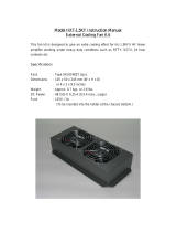
Does the Color
Wheel Start?
Check for 5vdc on
pin 3 of plug CN3
on the Ballast
Board (5 pin plug)
Fig. 1
Is the 5vdc
present?
Go to Chart 3
No
Yes
Check Ribbon Cable from
the Color Wheel to the
DMD Formatter Board.
Connector labeled [CW
OUT] on Formatter Metal
Shield
See
Footnote 1.
Problem
Resolved?
Yes
From Chart 1
Troubleshooting Flowchart 2006 DLP
“Lamp Fails To Start” (Chart 2)
Is Thermal
Sensor across
P805 Open?
Reset Thermal
Sensor
Change Ballast
Power Supply
Yes
No
Replace Optical
Engine
Unplug the TV
from AC and
remove the back
cover
Remove 2 screws
holding the optic
engine in place
and slide back to
gain access.
Re-Apply AC and
Power the set on
using the power
button.
12v present on
J11 Pins 1,2?
120vac across
P807B?
Approx 300v
present across
P811A?
No Yes
Check Chassis
Power Supply
Yes
No
Yes
Yes
Plug
CN3
Pin 1
Pin 2
Pin 3
Pin 4
Pin 5
Fig. 1
Black
Brown
Red
Orange
Yellow
No
No
Repair
Connections
DMD Formatter PCB
Ballast Power Supply PCB
Footnote 1. The Color Wheel will emit a high pitched whine when the TV Receiver is first turned on.
V1.0
No
Replacing the Light Engine under
Warranty requires a concession number
to be obtained from Technical Support.
1-800-345-9785
17

_
____________________________________________________________________________
_
2007 Toshiba America Consumer Products, LLC. Page 4 of 12
SMART2006001_Version2.2
Replacing the Light Engine under Warranty
requires a concession number to be obtained from
Technical Support. 1-800-345-9785
18

_
____________________________________________________________________________
_
2007 Toshiba America Consumer Products, LLC. Page 5 of 12
SMART2006001_Version2.2
Yes
Power Does Not
Cycle
9 Volts at
Capacitor
CS110(+)
Is POD Fan
Running?
No
A cycle is when the Blue
LED goes solid then after 10
seconds the Yellow LED
flashes 15 times before both
go out and restart again
20 Volts at
P823B Pin 3?
12 Volts at
P823B Pin 6?
Yes
No
Check F875 and
Power Supply
Check F873 and
Power Supply
No
5.0 Volts at
PB504 Pin 4?
Check F840 and
Power Supply
No
Yes
Change Regulator
PCB or POD Fan
9 Volts at
Capacitor
CS110(+)
3.3vdc at PB90
Pin 4?
No
Yes
Yes
Change Digital
PCB
Yes
No
6 Volts at Pin
18 of PB90?
Change Regulator
PCB
No
3.3 Volts at
PB80B Pin 19
and 20?
Change TV-Micro
PCB
Troubleshooting Flowchart 2006 DLP
“Dead / Does not Cycle” (Chart 4)
Is the Blue LED
Solid and the
Others Off?
Yes
Are the Optic
Engine Fans
Running?
No
Yes
Change Optic
Engine
No
Location PCB
PB504 Back AV
CS110 Back AV
P823B Regulator
P822B Regulator
PB90 Regulator
PB80B Regulator
No
Yes
NoYes
Change Regulator
PCB
Yes
V1.0
PB80B
PB90
P823B P822B
CS110
PB504
Back AV & Regulator PCB
19
/