Garmin G1000 - Beechcraft King Air C90A/C90GT/C90GTi Owner's manual
- Category
- Toys
- Type
- Owner's manual
This manual is also suitable for

190-00682-01 September 2015 Revision J
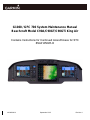
G1000 / GFC 700 System Maintenance Manual
Beechcraft Model C90A/C90GT/C90GTi King Air
Contains Instructions for Continued Airworthiness for STC
#SA01456WI-D

Page ii G1000/GFC700 System Maintenance Manual – C90A/C90GT/C90GTi King Air
Revision J 190-00682-01
© Copyright 2007-2015
Garmin Ltd. or its subsidiaries
All Rights Reserved
Except as expressly provided herein, no part of this manual may be reproduced, copied, transmitted,
disseminated, downloaded or stored in any storage medium, for any purpose without the express prior
written consent of Garmin. Garmin hereby grants permission to download a single copy of this manual
and of any revision to this manual onto a hard drive or other electronic storage medium to be viewed and
to print one copy of this manual or of any revision hereto, provided that such electronic or printed copy of
this manual or revision must contain the complete text of this copyright notice and provided further that
any unauthorized commercial distribution of this manual or any revision hereto is strictly prohibited.
Garmin International, Inc.
1200 E. 151
st
Street
Olathe, KS 66062 USA
Telephone: 913-397-8200
www.garmin.com
Garmin (Europe) Ltd.
Liberty House
Bulls Copse Road
Hounsdown Business Park
Southampton, SO40 9RB, UK
Phone: +44 (0) 23 8052 4000
Fax: +44 (0) 23 8052 4004
RECORD OF REVISIONS
Revision Revision Date Description ECO #
G 03/14/2014 Added two configurations to include Beech factory
equipped three-bladed propeller aircraft.
112589
H 1/27/2015 Added GRS 7800 and GWX 70 units. Updated
software load sections. Clerical updates.
119221
J 9/17/2015 Updated Section 4.12 procedure 132916

G1000/GFC700 System Maintenance Manual – C90A/C90GT/C90GTi King Air Page iii
190-00682-01 Revision J
DOCUMENT PAGINATION
Section Pagination
Table of Contents ii – xvi
Section 1 1-1 – 1-6
Section 2 2-1 – 2-14
Section 3 3-1 – 3-76
Section 4 4-1 – 4-40
Section 5 5-1 – 5-88
Section 6 6-1 – 6-16
Section 7 7-1 – 7-50
Section 8 8-1 – 8-6
Section 9 9-1 - 9-16
Section 10 10-1 - 10-2

Page iv G1000/GFC700 System Maintenance Manual – C90A/C90GT/C90GTi King Air
Revision J 190-00682-01
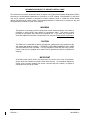
INFORMATION SUBJECT TO EXPORT CONTROL LAWS
This document may contain information which is subject to the Export Administration Regulations (“EAR”)
issued by the United States Department of Commerce (15 CFR, Chapter VII Subchapter C) and which
may not be exported, released or disclosed to foreign nationals inside or outside the United States
without first obtaining an export license. The preceding statement is required to be included on any and
all reproductions in whole or in part of this manual.
WARNING
This product, its packaging, and its components contain chemicals known to the State of
California to cause cancer, birth defects, or reproductive harm. This Notice is being
provided in accordance with California's Proposition 65. If you have any questions or
would like additional information, please refer to our web site at www.garmin.com/prop65
.
CAUTION
The GDU lens is coated with a special anti-reflective coating that is very sensitive to skin
oils, waxes and abrasive cleaners. CLEANERS CONTAINING AMMONIA WILL HARM
THE ANTI-REFLECTIVE COATING. It is very important to clean the lens using a clean,
lint-free cloth and an eyeglass lens cleaner that is specified as safe for anti-reflective
coatings.
IMPORTANT
All G1000 screen shots used in this document are current at the time of publication.
Screen shots are intended to provide visual reference only. All information depicted in
screen shots, including software file names, versions and part numbers, is subject to
change and may not be up to date.

G1000/GFC700 System Maintenance Manual – C90A/C90GT/C90GTi King Air Page v
190-00682-01 Revision J
TABLE OF CONTENTS
PARAGRAPH PAGE
1 INTRODUCTION ............................................................................................................ 1-1
1.1 C
ONTENT, SCOPE, PURPOSE .......................................................................................... 1-1
1.2 A
PPLICABILITY ................................................................................................................ 1-1
1.3 I
DENTIFYING AN STC CONFIGURATION ............................................................................ 1-1
1.4 G1000
SYSTEM SOFTWARE VERSION AND AIRCRAFT CONFIGURATION CHECK ................. 1-2
1.5 O
RGANIZATION ............................................................................................................... 1-3
1.6 D
EFINITIONS/ABBREVIATIONS.......................................................................................... 1-4
1.6.1 Units of Measure ......................................................................................................................... 1-4
1.7 P
UBLICATIONS ................................................................................................................ 1-5
1.8 R
EVISION AND DISTRIBUTION .......................................................................................... 1-6
2 SYSTEM DESCRIPTION ............................................................................................... 2-1
2.1 E
QUIPMENT DESCRIPTIONS ............................................................................................ 2-1
2.1.1 GDU 1040A PFD (2) & GDU 1500 MFD ..................................................................................... 2-1
2.1.2 GMA 1347D Audio Panel (2) ....................................................................................................... 2-2
2.1.3 GMC 710 AFCS Control Unit ...................................................................................................... 2-2
2.1.4 GCU 475 FMS Control Unit ......................................................................................................... 2-2
2.1.5 GIA 63W Integrated Avionics Unit (2) ......................................................................................... 2-3
2.1.6 GEA 71 Engine/Airframe Unit (2) ................................................................................................ 2-4
2.1.7 GTX 33 Mode S Transponder (2) ................................................................................................ 2-5
2.1.8 GDC 74B Digital Air Data Computer (2) ...................................................................................... 2-5
2.1.9 OAT Probe (2) ............................................................................................................................. 2-5
2.1.10 Attitude & Heading Reference System (2) .................................................................................. 2-6
2.1.11 GMU 44 Magnetometer (2) ......................................................................................................... 2-6
2.1.12 GDL 69A Datalink ........................................................................................................................ 2-7
2.1.13 Weather Radar ............................................................................................................................ 2-7
2.1.14 GSA 80/81 Servo Motors and GSM 85A/86 Servo Mounts ........................................................ 2-8
2.1.15 Comant CI428-410 / CI428-200 GPS/WAAS Antennas .............................................................. 2-8
2.1.16 Thommen 5A58.22.26K.28.1.XX Airspeed Indicator .................................................................. 2-8
2.1.17 Thommen 3A43.22.35F.28.1.FU Altimeter.................................................................................. 2-8
2.1.18 Mid-Continent 4200-10 Attitude Indicator .................................................................................... 2-8
2.1.19 L-3 PS-835(C or D Model) Emergency Standby Battery ............................................................. 2-9
2.1.20 Engine Signal Conditioning ......................................................................................................... 2-9

Page vi G1000/GFC700 System Maintenance Manual – C90A/C90GT/C90GTi King Air
Revision J 190-00682-01
2.2 G1000 OPTIONAL INTERFACES ..................................................................................... 2-10
2.3 E
LECTRICAL POWER DISTRIBUTION ............................................................................... 2-10
2.4 S
HIELD BLOCK GROUNDS ............................................................................................. 2-13
2.5 G1000
SYSTEM BLOCK DIAGRAM ................................................................................. 2-14
3 G1000 CONTROL, OPERATION, AND FULL SOFTWARE LOAD .............................. 3-1
3.1 G1000
CONTROL ........................................................................................................... 3-1
3.1.1 GDU 1040A and GDU 1500 Displays ......................................................................................... 3-1
3.1.2 GCU 475 - MFD Controller .......................................................................................................... 3-3
3.1.3 GMC 710 - AFCS Controls .......................................................................................................... 3-3
3.1.4 GMA 1347D Audio Panel ............................................................................................................ 3-4
3.2 G1000
OPERATION ........................................................................................................ 3-6
3.2.1 G1000 Normal Mode ................................................................................................................... 3-6
3.2.2 Reversionary Mode ..................................................................................................................... 3-7
3.2.3 Configuration Mode ..................................................................................................................... 3-8
3.3 G1000
SYSTEM SOFTWARE INFORMATION .................................................................... 3-13
3.3.1 G1000 Software Image ............................................................................................................. 3-13
3.3.2 Loader Card Creation ................................................................................................................ 3-14
3.3.3 Software Files ............................................................................................................................ 3-18
3.3.4 Configuration File Descriptions ................................................................................................. 3-18
3.3.5 Airframe and Optional Configurations ....................................................................................... 3-19
3.3.6 Configuration File Storage ......................................................................................................... 3-26
3.3.7 G1000 Software Load Summary ............................................................................................... 3-29
3.4 G1000
SYSTEM SOFTWARE AND CONFIGURATION LOAD PROCEDURE ........................... 3-30
3.4.1 Third Party STC Documentation and Optional Equipment List ................................................. 3-30
3.4.2 System Power Up ...................................................................................................................... 3-30
3.4.3 MFD & PFD Software Load ....................................................................................................... 3-30
3.4.4 Initial G1000 System Software and Baseline Configuration Load ............................................ 3-31
3.4.5 GRS AHRS / GMU 44 Magnetometer Software and Configuration Load ................................. 3-33
3.4.6 GWX 68 / 70 Radar Software and Configuration Load ............................................................. 3-33
3.4.7 GSM 85A / 86 Servo Mount Configuration Load ....................................................................... 3-33
3.4.8 King Air C90 Airframe Configuration ......................................................................................... 3-34
3.4.9 Weight and Airspeed Configuration ........................................................................................... 3-35
3.4.10 Non-Garmin Traffic System Option Configuration ..................................................................... 3-37
3.4.11 GTS 8XX Traffic System Option Configuration ......................................................................... 3-38
3.4.12 Stormscope (WX-500) Option Configuration ............................................................................. 3-38
3.4.13 ADF – 60 Option Configuration ................................................................................................ 3-38
3.4.14 Radar Altimeter Option Configuration ....................................................................................... 3-39

G1000/GFC700 System Maintenance Manual – C90A/C90GT/C90GTi King Air Page vii
190-00682-01 Revision J
3.4.15
DME 42 Option Configuration ................................................................................................... 3-39
3.4.16 GTX 33 Extended Squitter (ES) Option Configuration .............................................................. 3-39
3.4.17 ESP Support Option Configuration ............................................................................................ 3-40
3.4.18 GSR56 ....................................................................................................................................... 3-40
3.4.19 Update Config Module ............................................................................................................... 3-41
3.4.20 Jeppesen ChartView Enable ..................................................................................................... 3-41
3.4.21 FliteCharts Enable ..................................................................................................................... 3-42
3.4.22 TAWS B Enable ......................................................................................................................... 3-42
3.4.23 TAWS A Option ......................................................................................................................... 3-43
3.4.24 SVS/Pathways Enable .............................................................................................................. 3-43
3.4.25 ESP Enable ............................................................................................................................... 3-44
3.4.26 Optional Search and Rescue Enable ........................................................................................ 3-44
3.4.27 Aircraft Registration Number Entry ............................................................................................ 3-45
3.4.28 GMA 1347 #1 and GMA 1347 #2 Configuration Settings Check .............................................. 3-46
3.4.29 Clearing Default User Settings and Splash Screen Loading .................................................... 3-46
3.5 S
OFTWARE AND CONFIGURATION LOAD VERIFICATION ................................................... 3-48
3.5.1 Software Verification .................................................................................................................. 3-48
3.5.2 Airframe Configuration Verification ............................................................................................ 3-49
3.5.3 Stormscope (WX-500) Configuration Load Confirmation. ......................................................... 3-49
3.6 F
INAL G1000 SYSTEM SETUP ....................................................................................... 3-50
3.6.1 Navigation Database Loading ................................................................................................... 3-50
3.6.2 Terrain/Obstacle Database Card Loading ................................................................................. 3-51
3.6.3 Configuration of Navigation Map for Non-Garmin Traffic System ............................................. 3-52
3.7 G1000
SYSTEM TESTING .............................................................................................. 3-53
3.7.1 Display Testing .......................................................................................................................... 3-53
3.7.2 Cooling Fan Check .................................................................................................................... 3-56
3.7.3 Reversion Mode Check ............................................................................................................. 3-56
3.7.4 GPS Signal Acquisition ............................................................................................................. 3-57
3.7.5 VHF COMM Operational Check ................................................................................................ 3-58
3.7.6 Marker Beacon Test .................................................................................................................. 3-58
3.7.7 VOR/LOC/GS Test .................................................................................................................... 3-59
3.7.8 GTX 33 Testing ......................................................................................................................... 3-59
3.7.9 Airspeed Indicator Check .......................................................................................................... 3-59
3.7.10 TAWS B Functional Check ........................................................................................................ 3-60
3.7.11 FliteCharts Functional Check .................................................................................................... 3-61
3.7.12 ChartView Functional Check ..................................................................................................... 3-62
3.7.13 SafeTaxi Functional Check ....................................................................................................... 3-63

Page viii G1000/GFC700 System Maintenance Manual – C90A/C90GT/C90GTi King Air
Revision J 190-00682-01
3.7.14 Aircraft Weight Configuration Functional Check ....................................................................... 3-64
3.7.15 GWX Weather Radar Check ..................................................................................................... 3-68
3.7.16 Traffic System Functional Check (Optional Installation) ........................................................... 3-69
3.7.17 DME Functional Check (Optional Installation) .......................................................................... 3-70
3.7.18 ADF Functional Check (Optional Installation) ........................................................................... 3-71
3.7.19 Gen Purpose A429 Bus Check (Optional Installation) .............................................................. 3-71
3.7.20 Stormscope Functional Check (Optional Installation) ............................................................... 3-72
3.7.21 Non-Garmin Radio Altimeter Check (Optional Installation) ....................................................... 3-73
3.7.22 ESP Functional Check............................................................................................................... 3-74
3.7.23 Search and Rescue Functional Check ...................................................................................... 3-76
3.8 F
INAL TEST .................................................................................................................. 3-76
4 INSTRUCTIONS FOR CONTINUED AIRWORTHINESS .............................................. 4-1
4.1 A
IRWORTHINESS LIMITATIONS ......................................................................................... 4-1
4.2 S
ERVICING INFORMATION ................................................................................................ 4-3
4.2.1 On Condition Servicing ................................................................................................................ 4-3
4.2.2 Required Tools ............................................................................................................................ 4-4
4.2.3 Special Tools ............................................................................................................................... 4-4
4.3 M
AINTENANCE INTERVALS .............................................................................................. 4-5
4.3.1 Discontinued Maintenance ........................................................................................................ 4-10
4.4 V
ISUAL INSPECTION ...................................................................................................... 4-11
4.5 E
LECTRICAL BONDING TEST ......................................................................................... 4-16
4.5.1 Requirements ............................................................................................................................ 4-16
4.5.2 Test Equipment ......................................................................................................................... 4-16
4.5.3 Phase 3 Electrical Bonding Procedure ...................................................................................... 4-16
4.5.4 Phase 4 Electrical Bonding Procedure ...................................................................................... 4-18
4.6 GRS
77 OR GRS 7800 EARTH MAGNETIC FIELD UPDATES ............................................ 4-19
4.7 GSA
8X GREASING PROCEDURE .................................................................................. 4-19
4.8 F
LAPS-IN-MOTION DISCRETE INPUT CHECK ................................................................... 4-20
4.9 S
LIP CLUTCH TORQUE AND SERVO CURRENT DISPLAY CHECK PROCEDURE .................. 4-21
4.9.1 Automatic Slip Clutch Test Procedure (SW Version 0636.03 and Subs) .................................. 4-21
4.9.2 Manual Slip Clutch Test Procedure (SW Version 0636.02 and earlier) .................................... 4-23
4.9.3 Servo Adjustment Fixture Procedure ........................................................................................ 4-26
4.9.4 Servo Current Display Check .................................................................................................... 4-27
4.10 G1000
REDUNDANT CONNECTION CHECK ..................................................................... 4-29
4.11 E
NGINE DATA CHECK ................................................................................................... 4-32
4.11.1 Torque ....................................................................................................................................... 4-32

G1000/GFC700 System Maintenance Manual – C90A/C90GT/C90GTi King Air Page ix
190-00682-01 Revision J
4.11.2
ITT ............................................................................................................................................. 4-33
4.11.3 Oil Pressure ............................................................................................................................... 4-33
4.12 T
RIM ANNUNCIATOR CHECK .......................................................................................... 4-34
4.13 G1000
MISCOMPARE CHECKS ...................................................................................... 4-35
4.14 N
OSE AVIONICS COMPARTMENT FANS OPERATIONAL CHECK ........................................ 4-37
4.15 I
NSTRUMENT PANEL FANS OPERATIONAL CHECK........................................................... 4-37
4.16 S
TANDBY BATTERY PERIODIC CHECKS .......................................................................... 4-37
4.16.1 Charge Check ............................................................................................................................ 4-37
4.16.2 Capacity Test ............................................................................................................................. 4-39
4.16.3 Cell Isolation Test ...................................................................................................................... 4-40
4.16.4 Charging Procedure .................................................................................................................. 4-40
5 TROUBLESHOOTING ................................................................................................... 5-1
5.1 G1000
ALERTING SYSTEM .............................................................................................. 5-2
5.1.1 Aural & Audio Alerts .................................................................................................................... 5-3
5.2 S
YSTEM ANNUNCIATIONS ................................................................................................ 5-4
5.2.1 Failed Path Messages ................................................................................................................. 5-4
5.2.2 System Failure Troubleshooting ................................................................................................ 5-20
5.2.3 Engine/Airframe Instrument Failures ......................................................................................... 5-25
5.2.4 ADF/DME Failure ...................................................................................................................... 5-26
5.3 C90
SERIES SPECIFIC ALERTS ...................................................................................... 5-27
5.4 TAWS
TROUBLESHOOTING ........................................................................................... 5-28
5.5 S
YNTHETIC VISION AND PATHWAYS TROUBLESHOOTING ................................................ 5-29
5.6 GFC
700 AFCS TROUBLESHOOTING ............................................................................ 5-30
5.6.1 General Troubleshooting ........................................................................................................... 5-31
5.6.2 GFC Configuration Alerts (SW Version 0636.03 and Subs) ..................................................... 5-34
5.6.3 GFC Status Page ...................................................................................................................... 5-34
5.6.4 GIA Fault Log Descriptions ....................................................................................................... 5-35
5.6.5 GIA Pre-Flight Test Steps ......................................................................................................... 5-37
5.7 B
ACKUP COMMUNICATIONS PATH CHECKS .................................................................... 5-44
5.7.1 Overview .................................................................................................................................... 5-44
5.7.2 Data Path Failures ..................................................................................................................... 5-44
5.8 GDU
104X TROUBLESHOOTING .................................................................................... 5-45
5.8.1 GDU 104X Symptoms ............................................................................................................... 5-45
5.8.2 GDU 104X Alerts ....................................................................................................................... 5-46
5.9 GMA
SYMPTOMS ......................................................................................................... 5-54
5.9.1 GMA Alerts ................................................................................................................................ 5-55

Page x G1000/GFC700 System Maintenance Manual – C90A/C90GT/C90GTi King Air
Revision J 190-00682-01
5.10 GIA 63 TROUBLESHOOTING .......................................................................................... 5-56
5.10.1 COM Symptoms ........................................................................................................................ 5-56
5.10.2 NAV Symptoms ......................................................................................................................... 5-56
5.10.3 Glideslope Receiver Symptoms ................................................................................................ 5-56
5.10.4 GPS Symptoms ......................................................................................................................... 5-57
5.10.5 GIA Alert Messages ................................................................................................................... 5-58
5.11 GEA
TROUBLESHOOTING ............................................................................................. 5-65
5.11.1 GEA Alerts ................................................................................................................................. 5-65
5.12 GTX
TROUBLESHOOTING .............................................................................................. 5-66
5.12.1 GTX Alerts ................................................................................................................................. 5-66
5.13 GDL
69A TROUBLESHOOTING ...................................................................................... 5-67
5.13.1 GDL 69A Symptoms .................................................................................................................. 5-67
5.13.2 GDL 69A Alerts .......................................................................................................................... 5-68
5.14 GRS
AND GMU TROUBLESHOOTING ............................................................................. 5-69
5.14.1 AHRS Symptoms ....................................................................................................................... 5-69
5.14.2 GRS Alerts ................................................................................................................................. 5-70
5.14.3 GMU Alerts ................................................................................................................................ 5-72
5.14.4 Calibration Procedure E: Magnetometer Interference Test...................................................... 5-72
5.15 GDC
74B TROUBLESHOOTING ...................................................................................... 5-76
5.15.1 Air Data Symptoms .................................................................................................................... 5-76
5.15.2 GDC 74B Alerts ......................................................................................................................... 5-76
5.16 GWX
68 OR GWX 70 TROUBLESHOOTING .................................................................... 5-77
5.16.1 GWX Alerts and Problems ........................................................................................................ 5-77
5.17 GMC
710 TROUBLESHOOTING ...................................................................................... 5-78
5.17.1 GMC 710 Alerts and Problems .................................................................................................. 5-78
5.18 GCU
475 TROUBLESHOOTING ...................................................................................... 5-79
5.18.1 GCU 475 Alerts and Problems .................................................................................................. 5-79
5.19 S
OFTWARE/CONFIGURATION TROUBLESHOOTING .......................................................... 5-80
5.19.1 System Communication Hierarchy ............................................................................................ 5-81
5.20 B
ACKSHELL CONNECTORS ............................................................................................ 5-82
5.21 S
TANDBY ATTITUDE INDICATOR TROUBLESHOOTING ...................................................... 5-86
5.21.1 Standby Attitude Indicator Symptoms ....................................................................................... 5-86
5.22 S
TANDBY AIRSPEED INDICATOR TROUBLESHOOTING ..................................................... 5-86
5.22.1 Standby Airspeed Indicator Symptoms ..................................................................................... 5-86
5.23 S
TANDBY ALTIMETER TROUBLESHOOTING ..................................................................... 5-87
5.23.1 Standby Altimeter Symptoms .................................................................................................... 5-87

G1000/GFC700 System Maintenance Manual – C90A/C90GT/C90GTi King Air Page xi
190-00682-01 Revision J
5.24 STANDBY BATTERY TROUBLESHOOTING ........................................................................ 5-87
6 EQUIPMENT REMOVAL & REPLACEMENT ............................................................... 6-1
6.1 GDU
1040A/1500 .......................................................................................................... 6-1
6.2 GMA
1347D AUDIO PANEL ............................................................................................. 6-2
6.3 GIA
63W INTEGRATED AVIONICS UNITS .......................................................................... 6-2
6.4 GEA
71 ENGINE/AIRFRAME UNIT .................................................................................... 6-2
6.5 GTX
33 TRANSPONDER .................................................................................................. 6-3
6.6 GDC
74B AIR DATA COMPUTER ..................................................................................... 6-3
6.7 GTP
59 OAT PROBE ...................................................................................................... 6-3
6.8 GRS
77 / GRS 7800 AHRS ........................................................................................... 6-4
6.8.1 GRS 77 AHRS ............................................................................................................................. 6-4
6.8.2 GRS 7800 AHRS ......................................................................................................................... 6-4
6.9 GMU
44 MAGNETOMETER .............................................................................................. 6-4
6.10 GDL
69A ....................................................................................................................... 6-5
6.11 GSA
80/81 SERVOS ....................................................................................................... 6-5
6.12 GSM
85A / GSM 86 SERVO MOUNTS ............................................................................. 6-6
6.13 GCU
475 ....................................................................................................................... 6-6
6.14 GMC
710 ....................................................................................................................... 6-6
6.15 GWX
68 / GWX 70 ........................................................................................................ 6-7
6.16 C
ONFIGURATION MODULE ............................................................................................... 6-8
6.16.1 Configuration Module Removal & Replacement ......................................................................... 6-8
6.16.2 GRS 7800 Configuration Module Removal & Replacement ....................................................... 6-9
6.16.3 Configuration Module Checkout ................................................................................................ 6-10
6.17 GEA
71 BACKSHELL THERMOCOUPLE REMOVAL & REPLACEMENT ................................ 6-11
6.18 GPS/WAAS
ANTENNAS ............................................................................................... 6-12
6.19 E
NGINE SIGNAL CONDITIONERS .................................................................................... 6-12
6.20 S
ENIOR AEROSPACE PC920 SIGNAL CONDITIONING UNIT ............................................. 6-13
6.21 I
NSTRUMENT PANEL ANNUNCIATORS (PROP SYNCH AND STANDBY BATTERY) ................ 6-13
6.22 L-3
AVIONICS (BF GOODRICH) PS-835(C OR D MODEL) EMERGENCY BATTERY ............. 6-14
6.23 S
TANDBY AIRSPEED INDICATOR .................................................................................... 6-14
6.24 S
TANDBY ALTIMETER .................................................................................................... 6-14
6.25 S
TANDBY ATTITUDE INDICATOR ..................................................................................... 6-15
6.26 A
VIONICS COOLING FANS ............................................................................................. 6-15
6.27 GDU
COOLING FANS .................................................................................................... 6-16
7 G1000 HARDWARE REPLACEMENT - SOFTWARE LOADING AND TESTING ....... 7-1

Page xii G1000/GFC700 System Maintenance Manual – C90A/C90GT/C90GTi King Air
Revision J 190-00682-01
7.1 GDU 1040/1500 MFD & PFD ........................................................................................ 7-1
7.1.1 GDU Display Software and Configuration Loading ..................................................................... 7-2
7.1.2 PFD/MFD Test ............................................................................................................................. 7-5
7.2 GMA
1347D AUDIO PANEL ............................................................................................. 7-7
7.2.1 GMA Software and Configuration Loading .................................................................................. 7-7
7.2.2 GMA 1347D Test ......................................................................................................................... 7-8
7.3 GIA
63W INTEGRATED AVIONICS UNIT .......................................................................... 7-11
7.3.1 GIA 63W Software and Configuration Loading ......................................................................... 7-11
7.3.2 GIA 63W Test ............................................................................................................................ 7-12
7.4 GEA
71 ENGINE/AIRFRAME UNIT .................................................................................. 7-15
7.4.1 GEA 71 Software and Configuration Loading ........................................................................... 7-15
7.4.2 GEA 71 Test .............................................................................................................................. 7-16
7.4.3 Additional GEA 71 Functional Tests .......................................................................................... 7-17
7.5 GTX
33 TRANSPONDER ................................................................................................ 7-24
7.5.1 GTX 33 Software and Configuration Loading ........................................................................... 7-24
7.5.2 Aircraft Registration Number Configuration............................................................................... 7-25
7.5.3 GTX 33 Test .............................................................................................................................. 7-26
7.6 GDC
74B AIR DATA COMPUTER ................................................................................... 7-27
7.6.1 GDC Software and Configuration Loading ................................................................................ 7-27
7.6.2 Air Data Test (GDC 74B and STBY Instruments) ..................................................................... 7-28
7.6.3 Static Port Vertical Speed (Rate of Climb) Test ........................................................................ 7-31
7.6.4 OAT Probe Check ..................................................................................................................... 7-31
7.7 GRS
AHRS / GMU 44 MAGNETOMETER ....................................................................... 7-32
7.7.1 GRS/GMU Software and Configuration Loading ....................................................................... 7-32
7.7.2 GRS/GMU Calibration Procedures ............................................................................................ 7-34
7.7.3 Procedure A1: GRS AHRS Pitch/Roll Offset Calibration ......................................................... 7-35
7.7.4 Compass Rose Evaluation of Magnetic Disturbances for Magnetometer Calibration Procedure
(Optional).................................................................................................................................................. 7-36
7.7.5 Procedure B: GRS AHRS/GMU 44 Magnetic Calibration ........................................................ 7-37
7.7.6 Procedure D: Engine Run-Up Vibration Procedure ................................................................... 7-39
7.7.7 GRS/GMU Test ......................................................................................................................... 7-40
7.8 GDL
69A XM DATA LINK .............................................................................................. 7-41
7.8.1 GDL 69 Software and Configuration Loading ........................................................................... 7-41
7.8.2 GDL 69A Test ............................................................................................................................ 7-42
7.9 GSA
80/81 SERVOS ..................................................................................................... 7-42
7.9.1 GSA Software and Configuration Loading ................................................................................ 7-42
7.10 GCU
475 FMS CONTROLLER ....................................................................................... 7-44

G1000/GFC700 System Maintenance Manual – C90A/C90GT/C90GTi King Air Page xiii
190-00682-01 Revision J
7.10.1
GCU Software and Configuration Loading ................................................................................ 7-44
7.10.2 GCU 475 Test ............................................................................................................................ 7-44
7.11 GMC
710 AFCS CONTROLLER ..................................................................................... 7-45
7.11.1 GMC Software and Configuration Loading ............................................................................... 7-45
7.11.2 GMC 710 Test ........................................................................................................................... 7-46
7.12 GWX
68/70 WEATHER RADAR ...................................................................................... 7-47
7.12.1 GWX Software and Configuration Loading ............................................................................... 7-47
7.12.2 GWX Test .................................................................................................................................. 7-49
8 G1000 FUNCTION AND INTERFACE CHECKS .......................................................... 8-1
8.1 L
ANDING GEAR AURAL ALERT CHECK ............................................................................. 8-1
8.2 XM
AUDIO SUPPRESSION CHECK FOR AIRCRAFT WITH A TONE GENERATOR .................... 8-1
8.3 XM
AUDIO SUPPRESSION CHECK FOR AIRCRAFT WITHOUT A TONE GENERATOR ............. 8-2
8.3.1 Gear warning discrete ................................................................................................................. 8-2
8.3.2 Stall warning discrete .................................................................................................................. 8-3
8.4 TAWS
B FUNCTIONAL CHECK ......................................................................................... 8-4
8.5 W
EIGHT ON WHEELS AND LOW SPEED AWARENESS BAND TEST ...................................... 8-5
9 SYSTEM RETURN TO SERVICE PROCEDURE .......................................................... 9-1
9.1 B
ACKUP PATH SYSTEM TESTING ..................................................................................... 9-1
9.1.1 GPS Failure Test ......................................................................................................................... 9-1
9.1.2 GIA Failure Test .......................................................................................................................... 9-3
9.1.3 Display Failure Test ..................................................................................................................... 9-4
9.1.4 G1000 Backup Path Test ............................................................................................................ 9-5
9.2 M
ISCELLANEOUS SYSTEM TESTS .................................................................................... 9-7
9.2.1 G1000 Cooling Fan Fail Annunciation Check ............................................................................. 9-7
9.2.2 Standby Instrument Electrical Power Check ............................................................................... 9-8
9.3 GFC
700 GROUND TEST ................................................................................................ 9-9
9.3.1 Pre-Flight Test ............................................................................................................................. 9-9
9.3.2 AFCS Switch Check .................................................................................................................. 9-11
9.3.3 Autopilot Clutch Overpower Check ........................................................................................... 9-12
9.3.4 Manual Electric Pitch Trim Speed Check .................................................................................. 9-13
9.3.5 Autopilot Operation Check ........................................................................................................ 9-13
9.3.6 VOR/LOC/GS Test .................................................................................................................... 9-14
10 MAINTENANCE RECORDS ........................................................................................ 10-1

Page xiv G1000/GFC700 System Maintenance Manual – C90A/C90GT/C90GTi King Air
Revision J 190-00682-01
LIST OF ILLUSTRATIONS
FIGURE ................................................................................................................................................. PAGE
FIGURE 2-1, C90 ELECTRICAL DISTRIBUTION .................................................................................. 2-11
FIGURE 2-2, AVIONICS MASTER POWER SCHEMATIC .................................................................... 2-12
FIGURE 2-3, G1000 COMPONENT POWER SOURCES ..................................................................... 2-13
FIGURE 2-4, G1000 SYSTEM BLOCK DIAGRAM................................................................................. 2-14
FIGURE 3-1, GDU 1040A CONTROL INTERFACE ................................................................................. 3-1
FIGURE 3-2, GDU 1500 CONTROL INTERFACE ................................................................................... 3-2
FIGURE 3-3, G1000 SOFTKEYS ............................................................................................................. 3-2
FIGURE 3-4, MFD CONTROLS (GCU 475) ............................................................................................. 3-3
FIGURE 3-5, AFCS CONTROLS (GMC 710) ........................................................................................... 3-3
FIGURE 3-6, GMA 1347D PN 011-01257-00 CONTROLS ...................................................................... 3-4
FIGURE 3-7, GMA 1347D PN 011-01257-20 CONTROLS ...................................................................... 3-5
FIGURE 3-8, NORMAL MODE ................................................................................................................. 3-6
FIGURE 3-9, MANUAL REVERSION WITH MFD FAILURE .................................................................... 3-7
FIGURE 3-10, MANUAL REVERSION WITH PILOT PFD FAILURE ....................................................... 3-7
FIGURE 3-11, SET AND ACTV SOFTKEYS AND COLUMNS ................................................................ 3-9
FIGURE 3-12, LOSS OF COMMUNICATION ........................................................................................ 3-10
FIGURE 3-13, CONFIGURATION STATUS ........................................................................................... 3-10
FIGURE 3-14, DATA TRANSMISSION INDICATORS ........................................................................... 3-11
FIGURE 3-15, G1000 LRU CONFIGURATION FILE STORAGE ........................................................... 3-27
FIGURE 3-16, GRS/GDC CONFIGURATION SETTINGS STORAGE .................................................. 3-28
FIGURE 3-17, SOFTWARE/CONFIGURATION OVERVIEW ................................................................ 3-29
FIGURE 3-18, AIRCRAFT REGISTRATION .......................................................................................... 3-45
FIGURE 3-19, SYSTEM STATUS .......................................................................................................... 3-48
FIGURE 3-20, STORMSCOPE CONFIGURATION PAGE (REFERENCE ONLY) ................................ 3-49
FIGURE 3-21, MFD POWER UP PAGE (FORMAT REFERENCE) ....................................................... 3-53
FIGURE 3-22, PFD POWER-UP SYSTEM ANNUNCIATIONS ............................................................. 3-54
FIGURE 3-23, PFD NORMAL OPERATION .......................................................................................... 3-55
FIGURE 3-24, GDU REVERSIONARY MODE ....................................................................................... 3-56
FIGURE 3-25, AUX – GPS STATUS PAGE ........................................................................................... 3-57
FIGURE 3-26, MARKER BEACON SYMBOLOGY................................................................................. 3-58
FIGURE 4-1, SERVO GEAR................................................................................................................... 4-19
FIGURE 4-2, GIA I/O PAGE ................................................................................................................... 4-20
FIGURE 4-3, DISCRETE INDICATIONS ................................................................................................ 4-20
FIGURE 4-4, AIRFRAME CONFIGURATION PAGE ............................................................................. 4-21
FIGURE 4-5, GFC STATUS PAGE ........................................................................................................ 4-22

G1000/GFC700 System Maintenance Manual – C90A/C90GT/C90GTi King Air Page xv
190-00682-01 Revision J
FIGURE 4-6, GFC STATUS PAGE ........................................................................................................ 4-23
FIGURE 4-7, GFC STATUS PAGE ........................................................................................................ 4-28
FIGURE 4-8, STANDBY BATTERY ........................................................................................................ 4-38
FIGURE 4-9, POWER SUPPLY CONNECTION .................................................................................... 4-40
FIGURE 5-1, AUX – SYSTEM STATUS PAGE ........................................................................................ 5-1
FIGURE 5-2, ALERTS & ANNUNCIATIONS ............................................................................................ 5-2
FIGURE 5-3, ADVISORY SOFTKEY ANNUNCIATION ........................................................................... 5-2
FIGURE 5-4, SYSTEM ANNUNCIATIONS ............................................................................................... 5-4
FIGURE 5-5, AFCS ANNUNCIATION FIELD ......................................................................................... 5-30
FIGURE 5-6, GFC STATUS PAGE ........................................................................................................ 5-34
FIGURE 5-7, MAGNETOMETER INTERFERENCE TEST .................................................................... 5-73
FIGURE 5-8, MAGNETOMETER INTERFERENCE TEST COMPLETE ............................................... 5-75
FIGURE 5-9, GIA 63W BACKSHELL CONNECTORS ........................................................................... 5-82
FIGURE 5-10, GEA 71 BACKSHELL CONNECTORS ........................................................................... 5-83
FIGURE 5-11, GMA 1347D BACKSHELL CONNECTORS ................................................................... 5-83
FIGURE 5-12, GTX 33/33D BACKSHELL CONNECTORS ................................................................... 5-83
FIGURE 5-13, GDU 1040A/1500 BACKSHELL CONNECTOR (P10401 OR P15001) ......................... 5-84
FIGURE 5-14, GRS 77 BACKSHELL CONNECTOR (P771) ................................................................. 5-84
FIGURE 5-15, GRS 7800 BACKSHELL CONNECTOR (P78001) ......................................................... 5-84
FIGURE 5-16, GDC 74B BACKSHELL CONNECTOR (P74B1) ............................................................ 5-84
FIGURE 5-17, GDL 69A BACKSHELL CONNECTOR (P69A1) ............................................................. 5-85
FIGURE 5-18, GCU 475 BACKSHELL CONNECTOR (P4751) ............................................................. 5-85
FIGURE 5-19, GMC 710 BACKSHELL CONNECTOR (P7101) ............................................................ 5-85
FIGURE 5-20, GWX 68 BACKSHELL CONNECTOR (P681) ................................................................ 5-85
FIGURE 5-21, GWX 70 BACKSHELL CONNECTOR (P751) ................................................................ 5-85
FIGURE 5-22, SIGNAL CONDITIONER MATING CONNECTOR (PVIB1) ............................................ 5-86
FIGURE 6-1, CONFIGURATION MODULE INSTALLATION ................................................................... 6-8
FIGURE 6-2, GRS 7800 CONFIGURATION MODULE INSTALLATION ................................................. 6-9
FIGURE 6-3, GEA BACKSHELL THERMOCOUPLE ............................................................................. 6-11
FIGURE 7-1, G1000 NORMAL MODE CHECK ........................................................................................ 7-5
FIGURE 7-2, MARKER BEACON SYMBOLOGY................................................................................... 7-10
FIGURE 7-3, AUX – GPS STATUS PAGE (MFD) .................................................................................. 7-12
FIGURE 7-4, NORMAL ENGINE INSTRUMENT MARKINGS (MFD) .................................................... 7-17
FIGURE 7-5, AIRCRAFT REGISTRATION ............................................................................................ 7-25
FIGURE 7-6, GRS PITCH/ROLL OFFSET CALIBRATION PAGE ......................................................... 7-35
FIGURE 7-7, ENGINE RUN-UP TEST PAGE ........................................................................................ 7-39
FIGURE 7-8, NORMAL MODE AHRS CHECK ...................................................................................... 7-40

Page xvi G1000/GFC700 System Maintenance Manual – C90A/C90GT/C90GTi King Air
Revision J 190-00682-01
FIGURE 8-1, LOW SPEED AWARENESS BAND SYMBOLIZATION ..................................................... 8-5
FIGURE 9-1, GDU DATA VERIFICATION (ARINC 429) .......................................................................... 9-5
FIGURE 9-2, GIA DATA VERIFICATION (ARINC429/RS-232) ............................................................... 9-6
FIGURE 9-3, GIA DATA VERIFICATION (RS-485) ................................................................................. 9-7
FIGURE 9-4, PRE-FLIGHT TEST ........................................................................................................... 9-10
LIST OF TABLES
TABLE ................................................................................................................................................... PAGE
TABLE 1-1, MDL CONFIGURATIONS SUMMARY .................................................................................. 1-1
TABLE 1-2, REQUIRED DOCUMENTS ................................................................................................... 1-5
TABLE 1-3, REFERENCE PUBLICATIONS ............................................................................................. 1-6
TABLE 3-1, DATA INDICATOR SYMBOLS ............................................................................................ 3-11
TABLE 3-2, LRU TO CONFIGURATION FILE RELATIONSHIP ............................................................ 3-22
TABLE 3-3, OPTIONAL AIRFRAME WEIGHT CONFIGURATIONS ..................................................... 3-35
TABLE 4-1, MAINTENANCE INTERVALS ............................................................................................... 4-5
TABLE 4-2, DISCONTINUED MAINTENANCE INTERVALS ................................................................. 4-10
TABLE 4-3, NOSE SECTION VISUAL INSPECTION PROCEDURE .................................................... 4-11
TABLE 4-4, NOSE AVIONICS COMPARTMENT VISUAL INSPECTION PROCEDURE...................... 4-11
TABLE 4-5, PILOT’S COMPARTMENT VISUAL INSPECTION PROCEDURE .................................... 4-12
TABLE 4-6, INSTRUMENT PANEL G1000 EQUIPMENT VISUAL INSPECTION PROCEDURE ........ 4-13
TABLE 4-7, CABIN AREA VISUAL INSPECTION PROCEDURE .......................................................... 4-14
TABLE 4-8, REAR FUSELAGE AND EMPENNAGE VISUAL INSPECTION PROCEDURE ................ 4-15
TABLE 4-9, LIGHTNING STRIKE INSPECTION PROCEDURE ............................................................ 4-15
TABLE 4-10, MEASURED TORQUE ...................................................................................................... 4-25
TABLE 4-11, SLIP CLUTCH TORQUE SETTINGS................................................................................ 4-27
TABLE 4-12, STANDBY BATTERY REQUIRED EQUIPMENT ............................................................. 4-38
TABLE 5-1, SVS TROUBLESHOOTING ................................................................................................ 5-29
TABLE 5-2, SVS-RELATED ALERT MESSAGES ................................................................................. 5-29
TABLE 5-3, AFCS ANNUNCIATION TROUBLESHOOTING ................................................................. 5-31
TABLE 5-4, AFCS GENERAL TROUBLESHOOTING ........................................................................... 5-33
TABLE 5-5, MAGNETOMETER INTERFERENCE TEST SEQUENCE (EXAMPLE) ............................ 5-73
TABLE 6-1, CONFIGURATION MODULE KIT – 011-00979-03 ............................................................... 6-8
TABLE 6-2, GRS 7800 CONFIGURATION MODULE PARTS ................................................................. 6-9
TABLE 7-1, AIRSPEED AND ALTITUDE TABLE ................................................................................... 7-29
TABLE 7-2, VERTICAL SPEED TABLE ................................................................................................. 7-31
TABLE 7-3, REQUIRED GRS/GMU CALIBRATIONS ............................................................................ 7-34

G1000/GFC700 System Maintenance Manual – C90A/C90GT/C90GTi King Air Page 1-1
190-00682-01 Revision J
1 INTRODUCTION
1.1 Content, Scope, Purpose
This document provides Instructions for Continued Airworthiness (ICA) for the Garmin G1000 integrated
avionics and GFC700 Automatic Flight Control System (AFCS) as installed in the King Air C90 Series
using STC #SA01456WI-D. This document satisfies the requirements for continued airworthiness as
defined by 14 CFR Part 23.1529 and Appendix G. Information in this document is required to maintain
the continued airworthiness of the G1000 and GFC700 system.
1.2 Applicability
This document applies to all Model C90A/C90GT/C90GTi King Air aircraft equipped with the G1000 and
GFC700 AFCS systems. References to “C90 Series” throughout this document include C90A, C90GT,
and C90GTi models. Items in this document that are aircraft model(s) specific will identify the model(s)
instead of “C90 Series”.
The GFC 700 AFCS system is an integral part of the G1000 system and is included in “G1000 system”
references throughout this document.
Modification of an aircraft by this Supplemental Type Certificate (STC) obligates the aircraft operator to
include the maintenance information provided by this document in the operator’s Aircraft Maintenance
Manual and the operator’s Aircraft Scheduled Maintenance Program.
1.3 Identifying an STC Configuration
Table 1-1 lists the approved configurations for this STC as defined by the Master Drawing List (MDL)
listed in Table 1-2.
Software loads are governed primarily by the G1000 System Software Version number. The following
table identifies the System Software Version for this STC.
NOTE
G1000 System Software Version 0636.06 is added with STC MDL Rev. 13 and is the
recommended software version for new installations. G1000 System Software Versions
0636.01, 0636.02, 0636.03, and 0636.05 will remain to support fielded aircraft. Software
Version 0636.04 is not approved for installation.
Table 1-1, MDL Configurations Summary
MDL
Configuration
Aircraft
Model
G1000 System
Software Version
Notes
-1 C90A/C90GT King Air
0636.01
STC MDL Rev. 4 Approval
-1 C90A/C90GT King Air
0636.02
STC MDL Rev. 5 Approval
-1 C90A/C90GT/C90GTi King Air
0636.03
STC MDL Rev. 6 Approval
-1 C90A/C90GT/C90GTi King Air
0636.05
STC MDL Rev. 11 Approval
-1 C90A/C90GT/C90GTi King Air
0636.06
STC MDL Rev. 13 Approval
This STC addresses multiple C90 Series configurations. These configuration variants are added by
loading the applicable airframe configuration and related options. Refer the General Arrangement
drawing listed in Table 1-2 for additional information.

Page 1-2 G1000/GFC700 System Maintenance Manual – C90A/C90GT/C90GTi King Air
Revision J 190-00682-01
1.4 G1000 System Software Version and Aircraft Configuration Check
Follow these steps before any G1000 System Software is loaded for unit replacement to assure the
correct software and configuration files are loaded.
1. Inspect the aircraft maintenance logs for records of non-Garmin STCs installed. Inspect aircraft
records for signs of other alterations, including field updates and Service Bulletins.
2. Power on the G1000 system by setting the BAT switch to ON, then the EXT PWR switch to ON
and finally the AVIONICS MASTER switch to ON.
3. On the MFD start-up screen, check the upper right section of MFD splash screen for G1000
system software version and airframe configuration number.
4.
Write these numbers down for reference when loading software and configuration files.
An alternate location to find the G1000 system software version and airframe configuration number is on
the MFD AUX – SYSTEM STATUS page. On this page, this information is displayed in the AIRFRAME
window in the upper right corner of the display. The display shows the current G1000 airframe
configuration and system software version number. The system software version number is shown in the
following format: ‘System Software Version XXXX.XX’. It correlates to the G1000 software used to load
the software to the system in the example below:
System Software Version ‘0636.06’ = G1000 Software P/N 006-B0636-06
The General Arrangement drawing defines the approved G1000 software versions for this STC.

G1000/GFC700 System Maintenance Manual – C90A/C90GT/C90GTi King Air Page 1-3
190-00682-01 Revision J
1.5 Organization
The following outline briefly describes the organization of this manual:
Section 2: System Description
Provides a complete description of the type design change associated with installing the G1000
integrated cockpit system in the King Air C90 Series. An overview of the G1000 system interface is also
provided.
Section 3: G1000 Control & Operation
Presents basic control and operation information specifically tailored to maintenance practices. Basic
G1000 Configuration Mode operation is also described.
Section 4: Instructions for Continued Airworthiness
Provides maintenance instructions for continued airworthiness of the G1000 and GFC 700 systems.
Section 5: Troubleshooting
Provides troubleshooting information to aid in diagnosing and resolving potential problems with the
G1000 system.
Section 6: G1000 Equipment Removal & Replacement
Gives instructions for the removal and replacement of G1000 equipment.
Section 7: G1000 Hardware Replacement - Software Loading and Testing
Gives instructions for loading software, configuring, and testing of individual G1000 hardware removed for
service.
Section 8: G1000 Function and Interface Checks
Gives instructions for checking G1000 functions and interfaces for proper operation.
Section 9: System Return to Service Procedure
Specifies return-to-service procedures to be performed upon completion of maintenance of the G1000
system.

Page 1-4 G1000/GFC700 System Maintenance Manual – C90A/C90GT/C90GTi King Air
Revision J 190-00682-01
1.6 Definitions/Abbreviations
ADC: Air Data Computer
ADF: Automatic Direction Finder
ADTS: Air Data Test Set
AFCS: Automatic Flight Control System
AFM: Aircraft Flight Manual
AFMS: Aircraft Flight Manual Supplement
AHRS: Attitude Heading Reference System
CFR: Code of Federal Regulations
DME: Distance Measuring Equipment
EAU: Engine/Airframe Unit
ESP: Electronic Stability and Protection
GPS: Global Positioning System
HSDB: High-Speed Data Bus (Ethernet)
IAU: Integrated Avionics Unit
ICS: Inter-Com System
ITT: Interstage Turbine Temperature
LRU: Line Replaceable Unit
MFD: Multi-Function Flight Display
OAT: Outside Air Temperature
PFD: Primary Flight Display
STBY: Standby
STBY ATT: Standby Attitude Indicator
STBY ALT: Standby Altimeter
STBY A/S: Standby Airspeed Indicator
STC: Supplemental Type Certificate
TAWS: Terrain Awareness & Warning system
WAAS: Wide Area Augmentation System
VHF: Very High Frequency
1.6.1 Units of Measure
Unless otherwise stated, all units of measure are English units.
Page is loading ...
Page is loading ...
Page is loading ...
Page is loading ...
Page is loading ...
Page is loading ...
Page is loading ...
Page is loading ...
Page is loading ...
Page is loading ...
Page is loading ...
Page is loading ...
Page is loading ...
Page is loading ...
Page is loading ...
Page is loading ...
Page is loading ...
Page is loading ...
Page is loading ...
Page is loading ...
Page is loading ...
Page is loading ...
Page is loading ...
Page is loading ...
Page is loading ...
Page is loading ...
Page is loading ...
Page is loading ...
Page is loading ...
Page is loading ...
Page is loading ...
Page is loading ...
Page is loading ...
Page is loading ...
Page is loading ...
Page is loading ...
Page is loading ...
Page is loading ...
Page is loading ...
Page is loading ...
Page is loading ...
Page is loading ...
Page is loading ...
Page is loading ...
Page is loading ...
Page is loading ...
Page is loading ...
Page is loading ...
Page is loading ...
Page is loading ...
Page is loading ...
Page is loading ...
Page is loading ...
Page is loading ...
Page is loading ...
Page is loading ...
Page is loading ...
Page is loading ...
Page is loading ...
Page is loading ...
Page is loading ...
Page is loading ...
Page is loading ...
Page is loading ...
Page is loading ...
Page is loading ...
Page is loading ...
Page is loading ...
Page is loading ...
Page is loading ...
Page is loading ...
Page is loading ...
Page is loading ...
Page is loading ...
Page is loading ...
Page is loading ...
Page is loading ...
Page is loading ...
Page is loading ...
Page is loading ...
Page is loading ...
Page is loading ...
Page is loading ...
Page is loading ...
Page is loading ...
Page is loading ...
Page is loading ...
Page is loading ...
Page is loading ...
Page is loading ...
Page is loading ...
Page is loading ...
Page is loading ...
Page is loading ...
Page is loading ...
Page is loading ...
Page is loading ...
Page is loading ...
Page is loading ...
Page is loading ...
Page is loading ...
Page is loading ...
Page is loading ...
Page is loading ...
Page is loading ...
Page is loading ...
Page is loading ...
Page is loading ...
Page is loading ...
Page is loading ...
Page is loading ...
Page is loading ...
Page is loading ...
Page is loading ...
Page is loading ...
Page is loading ...
Page is loading ...
Page is loading ...
Page is loading ...
Page is loading ...
Page is loading ...
Page is loading ...
Page is loading ...
Page is loading ...
Page is loading ...
Page is loading ...
Page is loading ...
Page is loading ...
Page is loading ...
Page is loading ...
Page is loading ...
Page is loading ...
Page is loading ...
Page is loading ...
Page is loading ...
Page is loading ...
Page is loading ...
Page is loading ...
Page is loading ...
Page is loading ...
Page is loading ...
Page is loading ...
Page is loading ...
Page is loading ...
Page is loading ...
Page is loading ...
Page is loading ...
Page is loading ...
Page is loading ...
Page is loading ...
Page is loading ...
Page is loading ...
Page is loading ...
Page is loading ...
Page is loading ...
Page is loading ...
Page is loading ...
Page is loading ...
Page is loading ...
Page is loading ...
Page is loading ...
Page is loading ...
Page is loading ...
Page is loading ...
Page is loading ...
Page is loading ...
Page is loading ...
Page is loading ...
Page is loading ...
Page is loading ...
Page is loading ...
Page is loading ...
Page is loading ...
Page is loading ...
Page is loading ...
Page is loading ...
Page is loading ...
Page is loading ...
Page is loading ...
Page is loading ...
Page is loading ...
Page is loading ...
Page is loading ...
Page is loading ...
Page is loading ...
Page is loading ...
Page is loading ...
Page is loading ...
Page is loading ...
Page is loading ...
Page is loading ...
Page is loading ...
Page is loading ...
Page is loading ...
Page is loading ...
Page is loading ...
Page is loading ...
Page is loading ...
Page is loading ...
Page is loading ...
Page is loading ...
Page is loading ...
Page is loading ...
Page is loading ...
Page is loading ...
Page is loading ...
Page is loading ...
Page is loading ...
Page is loading ...
Page is loading ...
Page is loading ...
Page is loading ...
Page is loading ...
Page is loading ...
Page is loading ...
Page is loading ...
Page is loading ...
Page is loading ...
Page is loading ...
Page is loading ...
Page is loading ...
Page is loading ...
Page is loading ...
Page is loading ...
Page is loading ...
Page is loading ...
Page is loading ...
Page is loading ...
Page is loading ...
Page is loading ...
Page is loading ...
Page is loading ...
Page is loading ...
Page is loading ...
Page is loading ...
Page is loading ...
Page is loading ...
Page is loading ...
Page is loading ...
Page is loading ...
Page is loading ...
Page is loading ...
Page is loading ...
Page is loading ...
Page is loading ...
Page is loading ...
Page is loading ...
Page is loading ...
Page is loading ...
Page is loading ...
Page is loading ...
Page is loading ...
Page is loading ...
Page is loading ...
Page is loading ...
Page is loading ...
Page is loading ...
Page is loading ...
Page is loading ...
Page is loading ...
Page is loading ...
Page is loading ...
Page is loading ...
Page is loading ...
Page is loading ...
Page is loading ...
Page is loading ...
Page is loading ...
Page is loading ...
Page is loading ...
Page is loading ...
Page is loading ...
Page is loading ...
Page is loading ...
Page is loading ...
Page is loading ...
Page is loading ...
Page is loading ...
Page is loading ...
Page is loading ...
Page is loading ...
Page is loading ...
Page is loading ...
Page is loading ...
Page is loading ...
Page is loading ...
Page is loading ...
Page is loading ...
Page is loading ...
Page is loading ...
Page is loading ...
Page is loading ...
Page is loading ...
Page is loading ...
Page is loading ...
Page is loading ...
Page is loading ...
Page is loading ...
Page is loading ...
Page is loading ...
Page is loading ...
Page is loading ...
Page is loading ...
Page is loading ...
Page is loading ...
Page is loading ...
Page is loading ...
Page is loading ...
Page is loading ...
Page is loading ...
-
 1
1
-
 2
2
-
 3
3
-
 4
4
-
 5
5
-
 6
6
-
 7
7
-
 8
8
-
 9
9
-
 10
10
-
 11
11
-
 12
12
-
 13
13
-
 14
14
-
 15
15
-
 16
16
-
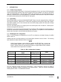 17
17
-
 18
18
-
 19
19
-
 20
20
-
 21
21
-
 22
22
-
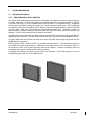 23
23
-
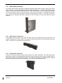 24
24
-
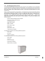 25
25
-
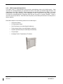 26
26
-
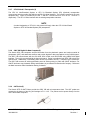 27
27
-
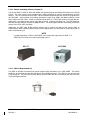 28
28
-
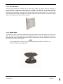 29
29
-
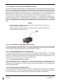 30
30
-
 31
31
-
 32
32
-
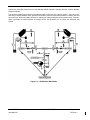 33
33
-
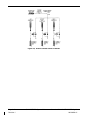 34
34
-
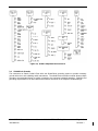 35
35
-
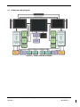 36
36
-
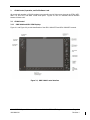 37
37
-
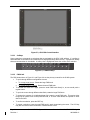 38
38
-
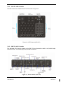 39
39
-
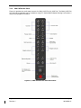 40
40
-
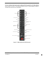 41
41
-
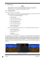 42
42
-
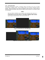 43
43
-
 44
44
-
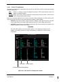 45
45
-
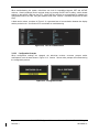 46
46
-
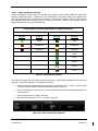 47
47
-
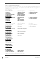 48
48
-
 49
49
-
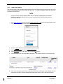 50
50
-
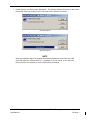 51
51
-
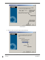 52
52
-
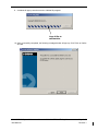 53
53
-
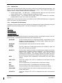 54
54
-
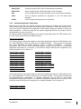 55
55
-
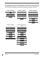 56
56
-
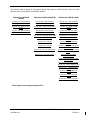 57
57
-
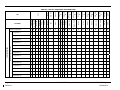 58
58
-
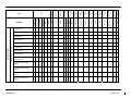 59
59
-
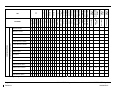 60
60
-
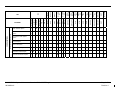 61
61
-
 62
62
-
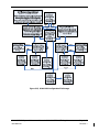 63
63
-
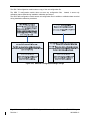 64
64
-
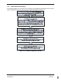 65
65
-
 66
66
-
 67
67
-
 68
68
-
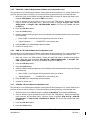 69
69
-
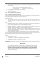 70
70
-
 71
71
-
 72
72
-
 73
73
-
 74
74
-
 75
75
-
 76
76
-
 77
77
-
 78
78
-
 79
79
-
 80
80
-
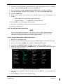 81
81
-
 82
82
-
 83
83
-
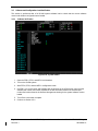 84
84
-
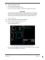 85
85
-
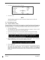 86
86
-
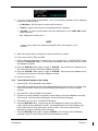 87
87
-
 88
88
-
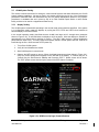 89
89
-
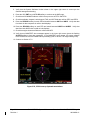 90
90
-
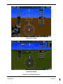 91
91
-
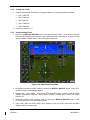 92
92
-
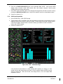 93
93
-
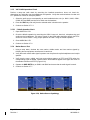 94
94
-
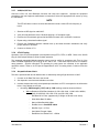 95
95
-
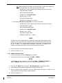 96
96
-
 97
97
-
 98
98
-
 99
99
-
 100
100
-
 101
101
-
 102
102
-
 103
103
-
 104
104
-
 105
105
-
 106
106
-
 107
107
-
 108
108
-
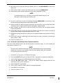 109
109
-
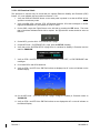 110
110
-
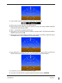 111
111
-
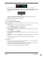 112
112
-
 113
113
-
 114
114
-
 115
115
-
 116
116
-
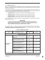 117
117
-
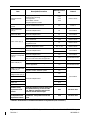 118
118
-
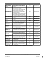 119
119
-
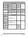 120
120
-
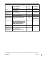 121
121
-
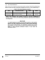 122
122
-
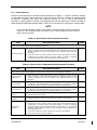 123
123
-
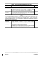 124
124
-
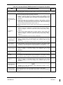 125
125
-
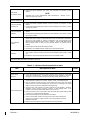 126
126
-
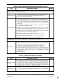 127
127
-
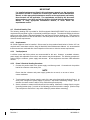 128
128
-
 129
129
-
 130
130
-
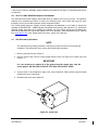 131
131
-
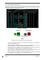 132
132
-
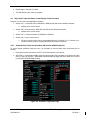 133
133
-
 134
134
-
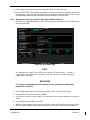 135
135
-
 136
136
-
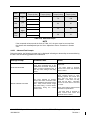 137
137
-
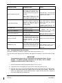 138
138
-
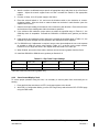 139
139
-
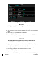 140
140
-
 141
141
-
 142
142
-
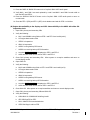 143
143
-
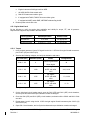 144
144
-
 145
145
-
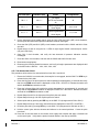 146
146
-
 147
147
-
 148
148
-
 149
149
-
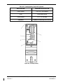 150
150
-
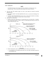 151
151
-
 152
152
-
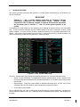 153
153
-
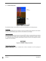 154
154
-
 155
155
-
 156
156
-
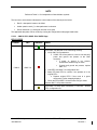 157
157
-
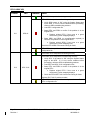 158
158
-
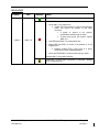 159
159
-
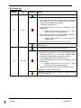 160
160
-
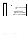 161
161
-
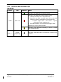 162
162
-
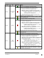 163
163
-
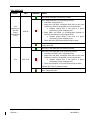 164
164
-
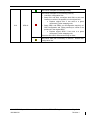 165
165
-
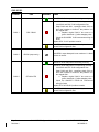 166
166
-
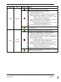 167
167
-
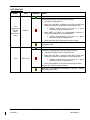 168
168
-
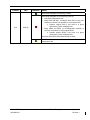 169
169
-
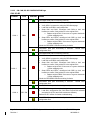 170
170
-
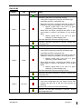 171
171
-
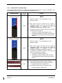 172
172
-
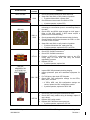 173
173
-
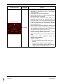 174
174
-
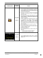 175
175
-
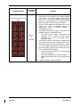 176
176
-
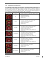 177
177
-
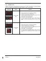 178
178
-
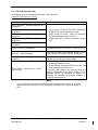 179
179
-
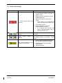 180
180
-
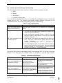 181
181
-
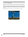 182
182
-
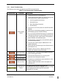 183
183
-
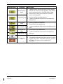 184
184
-
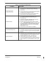 185
185
-
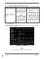 186
186
-
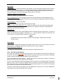 187
187
-
 188
188
-
 189
189
-
 190
190
-
 191
191
-
 192
192
-
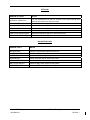 193
193
-
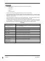 194
194
-
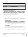 195
195
-
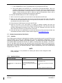 196
196
-
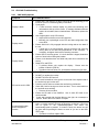 197
197
-
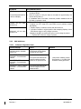 198
198
-
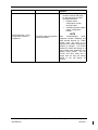 199
199
-
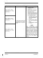 200
200
-
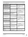 201
201
-
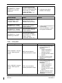 202
202
-
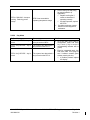 203
203
-
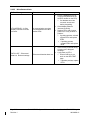 204
204
-
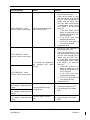 205
205
-
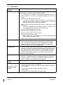 206
206
-
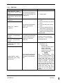 207
207
-
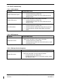 208
208
-
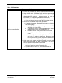 209
209
-
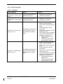 210
210
-
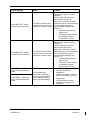 211
211
-
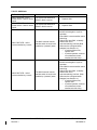 212
212
-
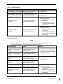 213
213
-
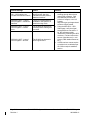 214
214
-
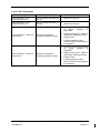 215
215
-
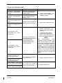 216
216
-
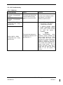 217
217
-
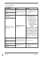 218
218
-
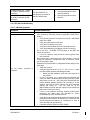 219
219
-
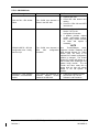 220
220
-
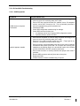 221
221
-
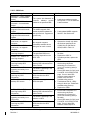 222
222
-
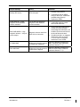 223
223
-
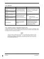 224
224
-
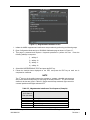 225
225
-
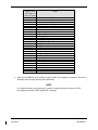 226
226
-
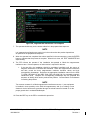 227
227
-
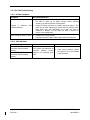 228
228
-
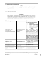 229
229
-
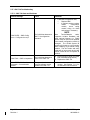 230
230
-
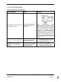 231
231
-
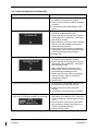 232
232
-
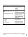 233
233
-
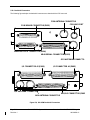 234
234
-
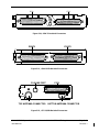 235
235
-
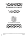 236
236
-
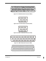 237
237
-
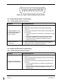 238
238
-
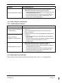 239
239
-
 240
240
-
 241
241
-
 242
242
-
 243
243
-
 244
244
-
 245
245
-
 246
246
-
 247
247
-
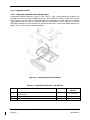 248
248
-
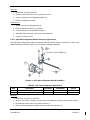 249
249
-
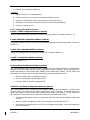 250
250
-
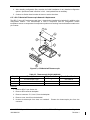 251
251
-
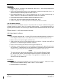 252
252
-
 253
253
-
 254
254
-
 255
255
-
 256
256
-
 257
257
-
 258
258
-
 259
259
-
 260
260
-
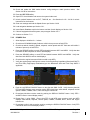 261
261
-
 262
262
-
 263
263
-
 264
264
-
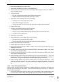 265
265
-
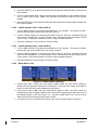 266
266
-
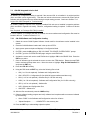 267
267
-
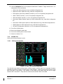 268
268
-
 269
269
-
 270
270
-
 271
271
-
 272
272
-
 273
273
-
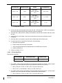 274
274
-
 275
275
-
 276
276
-
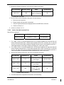 277
277
-
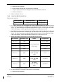 278
278
-
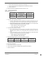 279
279
-
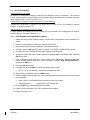 280
280
-
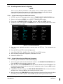 281
281
-
 282
282
-
 283
283
-
 284
284
-
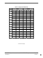 285
285
-
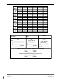 286
286
-
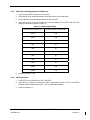 287
287
-
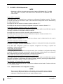 288
288
-
 289
289
-
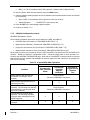 290
290
-
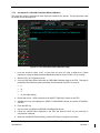 291
291
-
 292
292
-
 293
293
-
 294
294
-
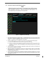 295
295
-
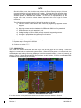 296
296
-
 297
297
-
 298
298
-
 299
299
-
 300
300
-
 301
301
-
 302
302
-
 303
303
-
 304
304
-
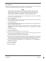 305
305
-
 306
306
-
 307
307
-
 308
308
-
 309
309
-
 310
310
-
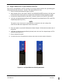 311
311
-
 312
312
-
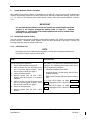 313
313
-
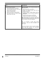 314
314
-
 315
315
-
 316
316
-
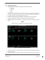 317
317
-
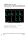 318
318
-
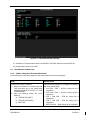 319
319
-
 320
320
-
 321
321
-
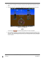 322
322
-
 323
323
-
 324
324
-
 325
325
-
 326
326
-
 327
327
-
 328
328
-
 329
329
-
 330
330


Garmin G1000 - Beechcraft King Air C90A/C90GT/C90GTi Owner's manual
- Category
- Toys
- Type
- Owner's manual
- This manual is also suitable for
Ask a question and I''ll find the answer in the document
Finding information in a document is now easier with AI
Related papers
-
Garmin G1000 - Beechcraft King Air C90A/C90GT/C90GTi Owner's manual
-
-
-
-
-
-
Garmin G1000 NXi - Beechcraft King Air C90A/C90GT/C90GTi Owner's manual
-
-
-
Other documents
-
Kmart 42881100 User manual
-
AG Neovo FMS-01 User manual
-
 Kenu AF1-KK-NA Datasheet
-
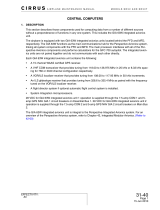 Cirrus SR22 Maintenance Manual
-
Empire Relaoder/Halo B Nf Shell Operating instructions
-
Kutai GCU-10 Owner's manual
-
Garmin International IPH-0060200 User manual
-
Groupe Brandt FTI-11_B Owner's manual
-
 Rockwell Collins AJK8221468 User manual
-
GE 120V Installation guide


