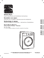
Kenmore 796.8099 Use & Care Manual And Installation Instructions
- Category
- Electric laundry dryers
- Type
- Use & Care Manual And Installation Instructions
This manual is also suitable for

Steam Dryer
Use & Care Guide and Installation Instructions
Secadora con vapor
Guía de uso y cuidado e Instrucciones de instalaci
ó
n
Sèche-linge à vapeur
Guide d’utilisation et entretien – Instructions d’installation
Models/Modelos/Modèles
Electric / Eléctrico / Électrique 796.8099#
Gas / Gas / À gaz
# = color number, número de color, numéro de couleur
P/No.MFL62512811
Sears Brands Management Corporation, Hoffman Estates, IL 60179
Sears Canada Inc., Toronto, Ontario, Canada M5B 2B8
www.sears.com
www.sears.ca
ESPAÑOL
FRANÇAIS
ENGLISH
FEATURES AND BENEFITS

PROTECTION AGREEMENTS
Master Protection Agreements
Congratulations on making a smart purchase. Your new
Kenmore
Ⓡ
product is designed and manufactured for
years of dependable operation. But like all products, it
may require preventive maintenance or repair from time
to time.
That’s when having a Master Protection
Agreement
can save you money and aggravation.
The Master Protection Agreement also helps extend the life
of your new product. Here’s what the Agreement*
includes:
•Parts and labor needed to help keep products
operating properly under normal use, not just
defects. Our coverage goes well beyond the
product warranty. No deductible, no functional
failure excluded from coverage—real protection.
•Expert service by a force of more than 10,000
authorized Sears service technicians, which means
someone you can trust will be working on your
product.
•Unlimited service calls and nationwide service, as
often as you want us, whenever you want us.
•No-lemon guarantee—replacement of your covered
product if four or more product failures occur within
twelve months.
•Product replacement if your covered product can’t
be fixed.
•Annual Preventive Maintenance Check at your
request—no extra charge.
•Fast help by phone—we call it Rapid Resolution.
Phone support from a Sears representative on all
products. Think of us as a talking owner’s manual.
•Power surge protection against electrical damage
due to power fluctuations.
•$250 food loss protection annually for any food
spoilage that is the result of mechanical failure of any
covered refrigerator or freezer.
•Rental reimbursement if repair of your covered
product takes longer than promised.
•10% discount off the regular price of any non-
covered repair service and related installed parts.
Once you purchase the Agreement, a simple phone call
is all that it takes for you to schedule service. You can
call anytime day or night or schedule a service
appointment online.
The Master Protection Agreement is a risk free
purchase.If you cancel for any reason during the
product warranty period, we will provide a full refund. Or
a prorated refund anytime after the product warranty
period expires. Purchase your Master Protection
Agreement today!
Some limitations and exclusions apply.
For prices and additional information in the U.S.A.
call 1-800-827-6655.
*Coverage in Canada varies on some items.
For full details call Sears Canada at 1-800-361-6665.
Sears Installation Service
For Sears professional installation of home appliances,
garage door openers, water heaters, and other major
home items, in the U.S.A. or Canada, call 1-800-4-MY-
HOME
Ⓡ
.
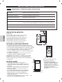
In the space below, record the date of purchase, model,
and serial number of your product. You will find the
model and serial number printed on an identification
plate located inside the dryer door. Have these items
of information available whenever you contact Sears
concerning your product.
Model No.
Date of Purchase
Serial No.
Save these instructions and your sales receipt for
future reference.
PRODUCT RECORD
INSTALLATION INSTRUCTIONS
Key Dimensions And Specifications...................................... 10
Location Requirements ......................................................... 10
Choose The Proper Location ................................................ 10
Clearances ............................................................................ 10
Installation With Optional Pedestal Base Or Stacking Kit
.............. 11
Optional Accessories ............................................................ 11
Gas Requirements (Gas Models Only) .................................. 12
Connecting Gas Dryers ....................................................12-13
Electrical Requirements ......................................................... 14
Connecting Electric Dryers ...............................................14-15
Venting The Dryer ................................................................. 16
Flow Check (Duct Condition Test) ......................................... 17
Leveling The Dryer ................................................................. 18
Reversing The Door Swing .................................................... 18
HOW TO USE
Control Panel Features .......................................................... 19
Operating The Dryer .............................................................. 20
Cycle Setting Buttons ........................................................... 20
Cycle Guide ........................................................................... 21
Sorting Loads ....................................................................... 22
Loading The Dryer ................................................................. 22
The Lcd Display .............................................................. 23-24
Cycle Option Buttons .......................................................25-26
Custom Program ................................................................... 27
Steam Functions ..............................................................27-29
Steam Cycle Guide ............................................................... 29
TROUBLESHOOTING
Before Calling for Service ................................................ 31–33
USER MAINTENANCE INSTRUCTIONS
Regular Cleaning ................................................................... 30
OPTIONAL ACCESSORIES/SPECIFICATIONS
Optional Accessories ............................................................ 34
Stacking Kit Installation ......................................................... 34
Setting Home Code ............................................................... 35
Home Code Clear .................................................................. 36
Pedestal Installation .............................................................. 37
Side Venting Kit Installation ................................................... 38
IMPORTANT SAFETY INSTRUCTIONS
What to Do if You Smell Gas ................................................... 3
Basic Safety Precautions ........................................................ 4
Grounding Instructions ............................................................ 5
Safety Instructions for Installation ........................................5-6
Safety Instructions for Steam Functions ................................. 6
Safety Instructions for Connecting Electricity ........................ 7
PARTS AND FEATURES
Special Features ...................................................................... 8
Key Parts and Components .................................................... 9
WARRANTY .................................................................... 39
INTRODUCTION
2
EnGLISH

3
EnGLISH
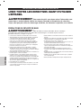
IMPORTANT SAFETY INSTRUCTIONS
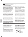
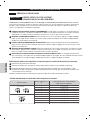
1. Do not try to light a match or cigarette, or
turn on any gas or electrical
appliance.
2. Do not touch any electrical switches. Do not
use any phone in your building.
3. Clear the room, building, or area of all oc-
cupants.
4. Immediately call your gas supplier
from a neighbor’s phone. Follow the gas
supplier’s instructions carefully.
5. If you cannot reach your gas
supplier, call the fire department.
WHAT TO DO IF YOU SMELL GAS:
READ ALL INSTRUCTIONS BEFORE USE
Your Safety and the safety of others is very important.
We have provided many important safety messages in this manual and on your appliance. Always read and obey all
safety messages.
This is the safety alert symbol.
This symbol alerts you to potential hazards that can kill or hurt you and others.
All safety messages will follow the safety alert symbol and either the word DANGER or WARNING.
These words mean:
wDANGER: You can be killed or seriously injured if you don’t immediately follow instructions.
wWARNING: You can be killed or seriously injured if you don’t follow instructions.
All safety messages will tell you what the potential hazard is, tell you how to reduce the chance of injury, and tell you
what can happen if the instructions are not followed.
•Donotinstallaclothesdryerwithexible
plasticventingmaterials.Ifexiblemetal
(foil type) duct is installed, it must be of a
specific type identified by the appliance
manufacturer as suitable for use with
clothesdryers.Flexibleventingmaterials
are known to collapse, be easily crushed,
and trap lint. These conditions will ob-
structclothesdryerairowandincrease
the risk of fire.
•Donotstoreorusegasolineorother
ammablevaporsandliquidsinthevicin-
ity of this appliance or any other appli-
ances.
•Installationandservicemustbe
performedbyaqualiedinstaller,service
agency, or the gas supplier.
•Installtheclothesdryeraccordingtothe
manufacturer’s instructions and local
codes.
•Savetheseinstructions.
wWARNING For your safety, the information in this manual must be
followedtominimizetheriskofreorexplosion,electricshock,ortopreventpropertydam-
age, personal injury, or loss of life.

READ ALL INSTRUCTIONS BEFORE USE
wWARNING For your safety, the information in this manual must be
followedtominimizetheriskofreorexplosion,electricshock,ortopreventpropertydam-
age, personal injury, or loss of life.
CALIFORNIA SAFE DRINKING WATER AND TOXIC ENFORCEMENT ACT
This act requires the governor of California to publish a list of substances known to the state to cause cancer,
birth defects, or other reproductive harm and requires businesses to warn customers of potential exposure to such
substances.
Gas appliances can cause minor exposure to four of these substances, namely benzene, carbon monoxide,
formaldehyde, and soot, caused primarily by the incomplete combustion of natural gas or LP fuels.
Properly adjusted dryers will minimize incomplete combustion. Exposure to these substances can be minimized further
by properly venting the dryer to the outdoors.
BASIC SAFETY PRECAUTIONS
wWARNING: To reduce the risk of fire, electric shock, or injury to persons when using this appliance,
follow basic precautions, including the following:
•Readallinstructionsbeforeusingthedryer.
•Beforeuse,thedryermustbeproperlyinstalledas
described in this manual.
•Donotplaceitemsexposedtocookingoilsinyour
dryer. Items contaminated with cooking oils may
contribute to a chemical reaction that could cause a
load to catch fire.
•Donotdryarticlesthathavebeenpreviously
cleaned in, washed in, soaked in, or spotted with
gasoline, dry-cleaning solvents, or other flammable
or explosive substances as they give off vapors that
could ignite or explode.
•Donotreachintothedryerifthedrumoranyother
part is moving.
•Donotrepairorreplaceanypartofthedryer
or attempt any servicing unless specifically
recommended in this Use and Care Guide or
in published user-repair instructions that you
understand and have the skills to carry out.
•Donottamperwithcontrols.
•Beforethedryerisremovedfromserviceor
discarded, remove the door to the drying
compartment.
•Donotallowchildrentoplayonorinthedryer.Close
supervision of children is necessary when the dryer is
used near children.
•Donotusefabricsoftenersorproductstoeliminate
static unless recommended by the manufacturer of
the fabric softener or product.
•Donotuseheattodryarticlescontainingfoam
rubber or similarly textured rubber-like materials.
•Keepareaaroundtheexhaustopeningandadjacent
surrounding areas free from the accumulation of lint,
dust, and dirt.
•Theinteriorofthedryerandexhaustventshouldbe
cleaned periodically by qualified service personnel.
•Donotinstallorstorethedryerwhereitwillbe
exposed to the weather.
•Alwayschecktheinsideofthedryerforforeign
objects.
•Cleanlintscreenbeforeoraftereachload.
4
EnGLISH
IMPORTANT SAFETY INSTRUCTIONS

5
EnGLISH
IMPORTANT SAFETY INSTRUCTIONS
GROUNDING INSTRUCTIONS
This appliance must be grounded. In the event of
malfunction or breakdown, grounding will reduce
the risk of electric shock by providing a path of least
resistance for electric current. This appliance must be
equipped with a cord having an equipment-grounding
conductor and a grounding plug. The plug must be
plugged into an appropriate outlet that is properly
installed and grounded in accordance with all local
codes and ordinances.
wWARNING — Improper connection
oftheequipment-groundingconductorcanresult
in a risk of electric shock. Check with a qualified
electrician or service person if you are in doubt as to
whether the appliance is properly grounded.
Do not modify the plug provided with the appliance. If it
will not fit the outlet, have a proper outlet installed by a
qualified electrician.
This appliance must be connected to a grounded metal,
permanent wiring system or an equipment-grounding
conductor must be run with the circuit conductors and
connected to the equipment-grounding terminal or lead
on the appliance.
Electrical shock can result if the dryer is not properly
grounded.
READ ALL INSTRUCTIONS BEFORE USE
SAFETY INSTRUCTIONS FOR INSTALLATION
•Properly ground dryer to conform with all
governing codes and ordinances. Follow details in
the installation instructions. Electrical shock can result
if the dryer is not properly grounded.
•Before use, the dryer must be properly installed as
described in this manual. Electrical shock can result
if the dryer is not properly grounded.
•Install and store the dryer where it will not be
exposedtotemperaturesbelowfreezingor
exposedtotheweather.
•All repairs and servicing must be performed
by an authorized servicer unless specifically
recommended in this Owner’s Guide. Use only
authorized factory parts. Failure to follow this
warning can cause serious injury, fire, electrical shock,
or death.
•To reduce the risk of electric shock, do not install
the dryer in humid spaces. Failure to follow this
warning can cause serious injury, fire, electrical shock,
or death.
wWARNING For your safety, the information in this manual must be
followedtominimizetheriskofreorexplosion,electricshock,ortopreventpropertydam-
age, personal injury, or loss of life.
wWARNING: To reduce the risk of fire, electric shock, or injury to persons when using this appliance,
follow basic precautions, including the following:
•Connect to a properly rated, protected, and sized
power circuit to avoid electrical overload. Improper
power circuit can melt, creating electrical shock and/or
fire hazard.
•Remove all packing items and dispose of all
shipping materials properly. Failure to do so can
result in death, explosion, fire, or burns.
•Placedryeratleast18in.abovetheoorfora
garage installation. Failure to do so can result in
death, explosion, fire, or burns.
•Keep all packaging from children. Packaging material
can be dangerous for children. There is a risk of
suffocation.
•Do not install nearby heat item. Such as stove,
cooking oven. Failure to do so can cause deform,
smoke and fire.
•Do not place candle and cigarettes on top of the
product. Failure to do so can cause deform, smoke
and fire.
•Remove all protective vinyl film from the product.
Failure to do so can cause deform, smoke and fire.

6
EnGLISH
IMPORTANT SAFETY INSTRUCTIONS
READ ALL INSTRUCTIONS BEFORE USE
SAFETY INSTRUCTIONS FOR INSTALLATION
wWARNING For your safety, the information in this manual must be
followedtominimizetheriskofreorexplosion,electricshock,ortopreventpropertydam-
age, personal injury, or loss of life.
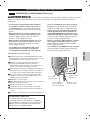
Exhaust/Ducting:
•GasdryersMUSTbeexhaustedtotheoutside.
Failure to follow these instructions
can result in fire or death.
•Thedryerexhaustsystemmustbeexhausted
to the outside of the dwelling. If the dryer is not
exhaustedoutdoors,somenelintandlarge
amountsofmoisturewillbeexpelledintothe
laundry area. An accumulation of
lint in any area of the home can create a health and
fire hazard.
•Useonlyrigidmetalorexiblemetal4-in.
diameter ductwork inside the dryer cabinet or for
exhaustingtotheoutside.Useofplasticorother
combustible ductwork can cause a fire. Punctured
ductwork can cause a fire if it collapses or becomes
otherwise restricted in use or during installation.
•Ductwork is not provided with the dryer, and you
should obtain the necessary ductwork locally. The
end cap should have hinged dampers to prevent
backdraft when the dryer is not in use. Failure to
follow these instructions can result in fire or death.
•Theexhaustductmustbe4in.(10.2cm)indiameter
withnoobstructions.Theexhaustductshouldbe
kept as short as possible. Make sure to clean any
old ducts before installing your new dryer. Failure to
follow these instructions can result in fire or death.
•Rigid or semi rigid metal ducting is recommended for
use between the
dryer and the wall. In special installations when
it is impossible to make a connection with the
aboverecommendations,aUL-listedexiblemetal
transition duct may be used between the dryer and
wall connection only. The use of this ducting will
affect drying time. Failure to follow these instructions
can result in fire or death.
•DO NOT use sheet metal screws or other fasteners
whichextendintotheductthatcouldcatchlintand
reducetheefciencyoftheexhaustsystem. Secure
all joints with duct tape. For complete details, follow
the Installation Instructions. Failure to follow these
instructions can result in fire or death.
SAFETY INSTRUCTIONS FOR STEAM FUNCTIONS
•Do not open the dryer door during steam cycles.
Failure to follow these instructions can result in a burn
hazard.
•Do not dry articles that have been previously
cleaned in, washed in, soaked in, or spotted
with gasoline, dry-cleaning solvents, or other
ammableorexplosivesubstancesastheygiveoff
vaporsthatcouldigniteorexplode.Failure to follow
these instructions can result in fire or death.
•Do not fill the steam feeder with gasoline, dry-
cleaningsolvents,orotherammableorexplosive
substances. Failure to follow these instructions can
result in fire or death.
•Do not touch the steam nozzle in the drum during
or after the steam cycle. Failure to follow these
instructions can result in a burn hazard.
•Do not fill the steam feeder with hot water (over
86°F/30°C).Failure to follow these instructions can
result in a burn hazard.
wWARNING: To reduce the risk of fire, electric shock, or injury to persons when using this appliance,
follow basic precautions, including the following:

7
EnGLISH
IMPORTANT SAFETY INSTRUCTIONS
SAFETY INSTRUCTIONS FOR CONNECTING ELECTRICITY
•Do not, under any circumstances, cut or remove
the ground prong from the power cord. To prevent
personal injury or damage to the dryer, the electrical
power cord must be plugged into a properly grounded
outlet.
•For personal safety, this dryer must be properly
grounded. Failure to do so can result in electrical
shock or injury.
•Refer to the installation instructions in this manual
forspecicelectricalrequirementsforyourmodel.
Failure to follow these instructions can create an
electrical shock hazard and/or a fire hazard.
•This dryer must be plugged into a properly
grounded outlet. Electrical shock can result if
the dryer is not properly grounded. Have the
walloutletandcircuitcheckedbyaqualied
electrician to make sure the outlet is properly
grounded. Failure to follow these instructions can
create an electrical shock hazard and/or a fire hazard.
•The dryer should always be plugged into its own
individual electrical outlet which has a voltage
rating that matches the rating plate. This provides
the best performance and also prevents overloading
house wiring circuits which could cause a fire hazard
from overheated wires.
•Never unplug your dryer by pulling on the power
cord. Always grip plug firmly and pull straight out
from the outlet. The power cord can be damaged,
resulting in a risk of fire and electrical shock.
•Repair or replace immediately all power cords
that have become frayed or otherwise damaged.
Do not use a cord that shows cracks or abrasion
damage along its length or at either end. The
power cord can melt, creating electrical shock and/or
fire hazard.
•When installing or moving the dryer, be careful not
to pinch, crush, or damage
the power cord. This will prevent injury and prevent
damage to the dryer from fire and electrical shock.
SAVE THESE INSTRUCTIONS
wWARNING: To reduce the risk of fire, electric shock, or injury to persons when using this appliance,
follow basic precautions, including the following:
READ ALL INSTRUCTIONS BEFORE USE
wWARNING For your safety, the information in this manual must be
followedtominimizetheriskofreorexplosion,electricshock,ortopreventpropertydam-
age, personal injury, or loss of life.

1
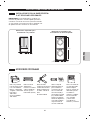
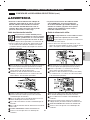
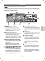
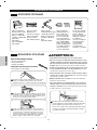
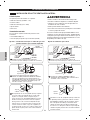
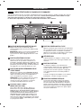
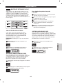
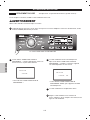
EASY-TO-USE CONTROL PANEL
Rotate the Cycle Selector Knob to select the
desired dry cycle. Add cycle options or adjust
settings with the touch of a button.
2
3
4
EASY-ACCESS REVERSIBLE DOOR
Wide-opening door provides easy access for
loading and unloading. Door swing can be
reversed to adjust for installation location.
ULTRA-CAPACITY STAINLESS STEEL DRUM
WITH DRUM LIGHT
The ultra-large stainless steel drum offers
superior durability. The drum is equipped with a
yellow light that illuminates when the dryer door
is open and turns off when the door is closed.
HELPFUL STEAM FUNCTIONS
steam technology allows you to inject fabrics
with a swirling jet of hot steam to refresh clothes,
reduce tatic, and make ironing easier. Simply
select the Steam Fresh cycle, or you can add a
Steam option to selected cycles.
5
LCD DISPLAY SCREEN
The easy-to-read LCD screen shows cycle
options and information and provides status
messages during operation.
6
FLOWSENSE™ DUCT BLOCKAGE
SENSING SYSTEM
The FLOWSENSE
™
duct blockage sensing
system detects and alerts you to blockages in the
filter and ductwork that reduce exhaust flow from
the dryer. This improves operating efficiency and
help minimize service calls, saving you money.
4
1
2
3
5
6
8
EnGLISH
SPECIAL FEATURES
PARTS AND FEATURES

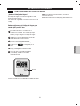
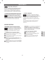
1
2
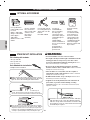
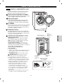
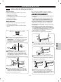
LEVELING FEET
Four leveling feet (two in the front, and two in the back)
adjust to improve dryer stability on uneven floors.
2
1
FRONT-MOUNT LINT FILTER
Front-mounted lint filter allows for easy access
and cleaning after every load.
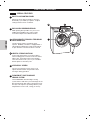
Terminal Block
Access Panel
(Electric Models)
Rear of Dryer
Power Cord Location
(Gas Models)
Gas
Connection
Location
(Gas Models)
Exhaust Duct
Outlet
In addition to the special features and components outlined in
the Special Features section, there are several other important
components that are referenced in this manual.
PLC MODEM
The PLC modem should only be removed by a
technician or servicer, or when installing the optional
Remote Laundry Monitor (purchased separately).
3
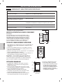
DRYING RACK
Use the drying rack with the RACK DRY cycle option. The
drying rack allows items, such as sweaters, delicates, and
gym shoes, to be placed in a flat position for drying.
4
3
STAINLESS STEEL CLEANER AND CLOTH
•Usageofcleaningcloth
DIRECTION: Saturate the cloth with Stainless
Steel Cleaner and wipe the surface in the
direction of the brush marks.
NOTE: Cloth itself will not scratch surfaces, but
can pick up particles that may scratch. CARE
INSRUCTION:Do not iron. Do not use fabric
softener. Wash separately or with non-linting
articles. Warm machine washing and low heat
drying keep it in best performance.
5
•StainlessSteelCleanerDirections
1. Shake well before using.
2. Apply a small amount of cleaner to paper towel or
sponge and rub surface to be cleaned.
3. Polish surface with clean, dry paper towel or cloth.
Included Accessories
Drying Rack
Stainless
Steel Cleaner
Cleaning Cloth
4
5
9
EnGLISH
FEATURES AND BENEFITS
KEY PARTS AND COMPONENTS
WARNING: To reduce the risk of injury to per-
sons when using this cleaner, follow basic precautions,
including the following:
•Donotputintoyoureyes.Failuretofollowthiswarning
can result in injury. If it comes in contact with eyes, rinse
thor oughly with water.
•Do not swallow this cleaner. Failure to do so can result
in injury. If in taken internally, do not induce vomiting; call
a physician.
•When using, gloves need to be put on. Failure to follow
this warning can result in injury. If it comes in
contact with skin, wash with soap and water.
•Do not operate the product with this cleaner in
the drum.
Failure to do so can result in damage of cloth.
•Keep out of reach of children.
Failure to do so can result in injury.
w

*Gas Models only.
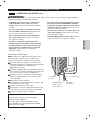
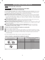
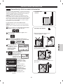
LOCATION REQUIREMENTS
CHOOSE THE PROPER LOCATION
CLEARANCES
30"
(76.1 cm)
50"
(127 cm)
20"
(50.8 cm)
4"
(10 cm)
18"
(45.72 cm)
4"
(10 cm)
IMPORTANT:
Read all installation instructions completely before
installing and operating your dryer!
It is important that you review this entire manual before
installing and using your dryer. It contains detailed
instructions concerning electrical connections, gas
connections and exhaust requirements.
•Storeandinstallthedryerwhereitwillnotbeexposedto
temperatures below freezing or exposed to outdoor weather
conditions.
•Choosealocationwithasolid,leveloor.
•Ifthedryerisbeinginstalledinagarage,placethedryeratleast
18 in. (45.7cm) above the floor.
•Properlygroundthedryertoconformwithallgoverningcodes
and ordinances.
•Toreducetheriskofelectricshock,donotinstallthedryerin
damp or wet locations.
IMPORTANT: If you are installing your dryer in a
manufactured or mobile home, please refer to the
section Special Electrical Requirements for Mobile or
Manufactured Homes on page 14.
•Mostinstallationsrequireaminimum5-1/2in.
(14 cm) clearance behind the dryer for the exhaust
ducting.
•Allowminimumclearancesofatleast1in.(2.5cm)on
the sides and back to minimize vibration and noise.
•Allowingadditionalclearanceforinstallationand
servicing is recommended.
•Besuretoallowforwall,door,oroormoldingsthat
may increase the required clearances.
•Allowatleast21in.(53.3cm)infrontofthedryerto
open the door.
Additional Instructions for closet
installations:
•Theclosetdoormustallowfor
sufficient airflow. Refer to the
diagram to the left for minimum
vent opening requirements.
A louvered door is also acceptable.
27"
(68.6 cm)
1"
(2.54 cm)
1"
(2.54 cm)
24 in.
2
(155 cm
2
)
3"
(7.6 cm)
3"
(7.6 cm)
48 in.
2
(310 cm
2
)
Closet Door Vent
Requirements
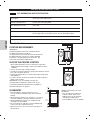
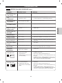
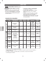
Description Steam Dryer (Gas and Electric)
Electrical Requirements Please refer to the rating label.
Gas Requirements* NG: 6-8 in. WC
Gas Requirements* LP: 10–13 in. WC
Dimensions 27” (W) X 30” (D) X 38 11/16 (H), 50” (D with door open)
68.6 cm (W) X 76.1 cm (D) X 98.3 cm (H), 127 cm (D with door open)
Net Weight 131lb. (59.4kg)
Drying Capacity IEC 7.3 cu.ft.
10
EnGLISH
INSTALLATION INSTRUCTIONS
KEY DIMENSIONS AND SPECIFICATIONS

IMPORTANT: If you are installing your dryer
using an optional pedestal base or stacking kit,
please refer to the instructions on page 34-37
in this manual, or refer to the instructions
included with the accessory.
30"
(76.1 cm)
4"
(10 cm)
27"
(68.6 cm)
1"
(2.54 cm)
1"
(2.54 cm)
77
1
/2"
(190.5 cm)
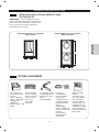
RequiredDimensionsforInstallation
With Pedestal
RequiredDimensionsforInstallation
WithStackingKit
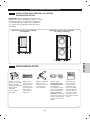
OPTIONAL ACCESSORIES
Use a pedestal to
make laundry easier
to reach.
White = 796.51022
Ginger = 796.51028
Chili Pepper =
796.51029
Stainless Steel = 796.
51026
Use the stacking
kit to mount the
dryer on top of the
washer to save
floor space
D26 18992
(Titanium)
Use the side vent kit
for venting directly on
either side or on the
bottom.
Kit # D26-49670
Use the LP
CONVERSION
KIT for changing
the dryer gas
connections from
Natural Gas (NG) to
Liquefied Propane
Gas (LP)
4948EL4002C
NOTE: Installation of
the LP conversion kit
must be
performed by a
qualified service
professional.
Remote Laundry
Monitor
Check the status
of a load of laundry
from anywhere in
the house without
special wiring. This
unit plugs into any
standard household
outlet and toggles
between washer and
dryer status.
11
EnGLISH
INSTALLATION INSTRUCTIONS
INSTALLATION WITH OPTIONAL PEDESTAL BASE
OR STACKING KIT

wWARNING: To reduce the risk of fire, electric shock, or injury to persons when using this appliance,
follow basic precautions, including the following:
•Gassupplyrequirements:
As shipped from the factory, this dryer is
configured for use with (NG) natural gas. It can
beconvertedforusewithLP(LiqueedPropane)
gas.Gaspressuremustnotexceed8in.water
column for (NG), or 13 in. water column for (LP).
•Aqualiedserviceorgascompanytechnician
must connect the dryer to the gas service. Failure
to do so can result in fire, explosion, or death.
• Isolate the dryer from the gas supply system by
closing its individual manual shutoff valve during
any pressure testing of the gas supply. Failure to
do so can result in fire, explosion, or death.
•Supplylinerequirements:Yourlaundryroom
must have a rigid gas supply line to your dryer. In
theUnitedStates,anindividualmanualshutoff
valveMUSTbeinstalledwithinatleast6ft.(1.8
m) of the dryer, in accordance with the National
FuelGasCodeANSIZ223.1orCanadiangas
installationcodeCSAB149.1.A1/8in.NPTpipe
plug must be installed. Failure to do so can result
inre,explosion,ordeath.
•Ifusingarigidpipe,therigidpipeshouldbe1/2in.
IPS.Ifacceptableunderlocalcodesand
ordinances and when acceptable to your gas
supplier,3/8in.approvedtubingmaybeused
wherelengthsarelessthan20ft.(6.1m).Larger
tubingshouldbeusedforlengthsinexcessof
20ft.(6.1m). Failure to do so can result in fire,
explosion, or death.
•Connect the dryer to the type of gas shown on
the nameplate. Failure to do so can result in fire,
explosion, or death.
•To prevent contamination of the gas valve,
purge the gas supply of air and sediment before
connecting the gas supply to the dryer. Before
tightening the connection between the gas supply
and the dryer, purge remaining air until the odor
of gas is detected. Failure to do so can result in fire,
explosion, or death.
•DONOTuseanopenametoinspectforgas
leaks.Useanoncorrosiveleakdetectionuid.
Failure to do so can result in fire, explosion, or death.
•UseonlyanewAGA-orCSA-certiedgassupply
linewithexiblestainlesssteelconnectors.
Failure to do so can result in fire, explosion, or death.
•Securelytightenallgasconnections. Failure to do
so can result in fire, explosion, or death.
•UseTeon£ótapeorapipe-jointcompoundthat
isinsolubleinLiqueedPetroleum(LP)gason
all pipe threads. Failure to do so can result in fire,
explosion, or death.
•DO NOT attempt any disassembly of the dryer;
anydisassemblyrequirestheattentionandtools
ofanauthorizedandqualiedserviceperson
or company. Failure to do so can result in fire,
explosion, or death.
•Do not, under any circumstances, cut or remove
the third (ground) prong from the power cord.
Failure to follow this warning can result in fire,
explosion, or death.
•For personal safety, this dryer must be properly
grounded. Failure to follow this warning can result in
fire, explosion, or death.
•Thepowercordofthisdryerisequippedwith
a 3-prong (grounding) plug which mates with
a standard 3-prong (grounding) wall outlet to
minimize the possibility of electric shock hazard
from this appliance. Failure to follow this warning
can result in fire, explosion, or death.
•Thisdryermustbepluggedintoa120-VAC,60-Hz.
grounded outlet protected by a 15-ampere fuse
or circuit breaker. Failure to follow this warning can
result in fire, explosion, or death.
•Where a standard 2-prong wall outlet is
encountered, it is your personal responsibility
and obligation to have it replaced with a properly
grounded 3-prong wall outlet. Failure to follow this
warning can result in fire, explosion, or death.
Ensure proper
ground exists
before use.
3-prong
grounding
plug
3-prong
grounding type
wall receptacle
12
EnGLISH
INSTALLATION INSTRUCTIONS
GAS REQUIREMENTS (GAS MODELS ONLY)
CONNECTING GAS DRYERS
ElectricalRequirementsforGasModelsOnly

wWARNING: To reduce the risk of fire, electric shock, or injury to persons when using this appliance,
follow basic precautions, including the following:
•Installation and service must be performed by a
qualiedinstaller,serviceagency,orthegas
supplier. Failure to do so can result in fire, explosion,
or death.
•Useonlyanewstainlesssteelexibleconnector
and a new AGA-certified connector. Failure to do
so can result in fire, explosion, or death.
•A gas shutoff valve must be installed within 6 ft.
(1.8 m) of the dryer. Failure to do so can result in
fire, explosion, or death.
•The dryer is configured for Natural Gas when
shipped from the factory. Make sure that the dryer
isequippedwiththecorrectburnernozzleforthe
typeofgasbeingused(NaturalGasorLiqueed
Petroleum). Failure to do so can result in fire,
explosion, or death.
•If necessary, the correct nozzle (for the LP nozzle
kit,orderpartnumber4948EL4002C)shouldbe
installedbyaqualiedtechnicianandthechange
should be noted on the dryer. Failure to do so can
result in fire, explosion, or death.
•All connections must be in accordance with local
codes and regulations. Failure to do so can result
in fire, explosion, or death.
•GasdryersMUSTexhausttotheoutdoors. Failure
to do so can result in fire, explosion, or death.
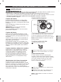
NOTE: This dryer is configured from the factory set for
Natural Gas (NG). If dryer is to be used with LP gas,
it must be converted by a qualified service technician.
Make sure that the gas supply to the laundry room is
turned OFF and the dryer is unplugged. Confirm that the
type of gas available in your laundry room is
appropriate for the dryer.
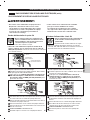
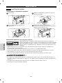
Remove the shipping cap from the gas fitting at the back
of the dryer. Be careful not to damage the threads of the
gas connector when removing the shipping cap.
Connect the dryer to your laundry room’s gas supply
using a new flexible stainless steel connector with a
3/8 in. NPT fitting.
NOTE:DO NOT use old connectors.
Securely tighten all connections between the dryer and
your laundry room’s gas supply.
Turn on your laundry room’s gas supply.
Check all pipe c onnections (both internal and external)
for gas leaks with a noncorrosive leak-detection fluid.
Proceed to Venting the Dryer on page 16.
The BTU rating of this dryer is AGA-certified for
elevations below 10,000 feet.
If your gas dryer is being installed at an elevation
above 10,000 feet, it must be derated by a qualified
technician or gas supplier.
1
2
3
4
5
6
7
13
EnGLISH
INSTALLATION INSTRUCTIONS
CONNECTING GAS DRYERS (cont.)
Connecting the Gas Supply
3/8” NPT Gas
Connection
AGA/CSA-Certified
Stainless Steel
Flexible Connector
Gas Supply
Shutoff Valve
1/8” NPT Pipe Plug
High-Altitude Installations

wWARNING: To help prevent fire,
electric shock, serious injury, or death, the wiring
and grounding must conform to the latest edition
of the National Electrical Code, ANSI/NFPA 70 and
all applicable local regulations. Please contact a
qualified electrician to check your home’s wiring
and fuses to ensure that your home has adequate
electrical power to operate the dryer.
wWARNING: To reduce the risk of
fire, electric shock, or injury to persons when using
this appliance, follow basic precautions, including
the following:
•Any installation in a manufactured or mobile
home must comply with the Manufactured Home
Construction and Safety Standards Title 24 CFR, Part
32-80 or Standard CAN/CSA0Z240 MH and local
codes and ordinances.
•A4-wireconnectionisrequiredforallmobileand
manufactured home installations, as well as all
newconstructionafterJanuary1,1996. Failure to
do so can result in fire, explosion, or death.
wWARNING: To reduce the risk of
fire, electric shock, or injury to persons when using
this appliance, follow basic precautions, including
the following:
•This dryer must be connected to a grounded
metal,permanentwiringsystem,oranequip-
ment grounding conductor must be run with the
circuitconductorsandconnectedtotheequip-
ment grounding terminal or lead on the dryer.
Failure to do so can result in fire, explosion, or
death.
•The dryer has its own terminal block that must
beconnectedtoaseparate240VAC,60-Hertz,
singlephasecircuit,fusedat30amperes(the
circuit must be fused on both sides of the
line).ELECTRICALSERVICEFORTHEDRYER
SHOULDBEOFTHEMAXIMUMRATEVOLTAGE
LISTEDONTHENAMEPLATE.DONOT
CONNECTDRYERTO110-,115-,OR120-VOLT
CIRCUIT. Heating elements are available for field
installation in dryers which are to be connected
to an electrical service of a different voltage
than that listed on the rating plate. Failure to fol-
low these instructions can result in fire, explosion,
or death.
• If branch circuit to dryer is 15 ft. (4.5 m) or less
in length, use UL (Underwriters Laboratories)
listedNo.-10AWGwire(copperwireonly),or
asrequiredbylocalcodes.Ifover15ft.(4.50
m), use UL-listed No.-8 AWG wire (copper wire
only),orasrequiredbylocalcodes.Allowsuf-
ficient slack in wiring so dryer can be moved
from its normal location when necessary. Failure
to do so can result in fire, explosion, or death.
•The power cord (pigtail) connection between
wallreceptacleanddryerterminalblockIS
NOT supplied with the dryer. Type of pigtail and
gauge of wire must conform to local codes and
with instructions on the following pages. Failure
to follow these instructions can result in fire, explo-
sion, or death
•A4-wireconnectionisrequiredforallnewcon-
structionafterJanuary1,1996.A4-wireconnec-
tion must be used where local codes do not per-
mit grounding through the neutral wire. Failure to
do so can result in fire, explosion, or death.
Electrical Requirements for Electric
Models Only
14
EnGLISH
INSTALLATION INSTRUCTIONS
ELECTRICAL REQUIREMENTS
CONNECTING ELECTRIC DRYERS
Special Electrical Requirements for Mobile
or Manufactured Homes

wWARNING:
•Connect the power cord to the terminal block.
Each colored wire should be connected to same
color screw. Wire color indicated on manual is
connected to the same color screw in block.
Failure to follow these instructions may result in a
short or overload.
•Grounding through the neutral conductor is
prohibitedfor:(1)newbranch-circuitinstallations,
(2) mobile homes, (3) recreational vehicles, and
(4) areas where local codes prohibit grounding
through the neutral conductor.
•A4-wireconnectionisrequiredforallmobileand
manufactured home installations, as well as all
new construction after January 1, 1996.
•AUL-listedstrainreliefisrequired.
•Usea30-amp,240-volt,4-wire,UL-listedpowercord
with#10AWG-minimumcopperconductor and closed
loop or forked terminals with upturned ends.
• A 3-wire connection is NOT permitted on new
constructionafterJanuary1,1996.
•AUL-listedstrainreliefisrequired.
•AUL-listedstrainreliefisrequired.
•Usea30-amp,240-volt,3-wire,UL-listedpowercord
with #10 AWG-minimum copper conductor and closed
loop or forked terminals with upturned ends.
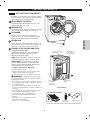
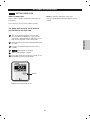
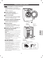
Remove the terminal block access cover on the upper
back of the dryer.
Install a UL-listed strain relief into the power cord
through-hole.
Thread a 30-amp,240-volt,4-wire,UL-listedpower
cordwith#10AWG-minimumcopperconductor
through the strain relief.
Remove the terminal block access cover on the upper
back of the dryer.
Install a UL-listed strain relief into the power cord
through-hole.
Thread a 30-amp,240-volt,3-wire,UL-listedpower
cordwith#10AWG-minimumcopperconductor
through the strain relief.
Transfer the dryer’s ground wire from behind the green
ground screw to the center screw of the terminal block.
Attach the two hot leads of the power cord to the outer
terminal block screws.
Attach the white neutral wire to the center screw of the
terminal block.
Attach the power cord ground wire to the green ground
screw.
TIGHTEN ALL SCREWS SECURELY.
Reinstall the terminal block access cover.
Attach the two hot leads (black and red) of the power
cord to the outer terminal block screws.
Attach the neutral wire to the center terminal block
screw.
Connect the external ground (if required by local codes)
to the green ground screw.
TIGHTEN ALL SCREWS SECURELY.
Reinstall the terminal block access cover.
1 1
2 2
3 3
4 4
5 5
6 6
7 7
8
8
9
15
EnGLISH
INSTALLATION INSTRUCTIONS
CONNECTING ELECTRIC DRYERS (cont.)
CONNECTING ELECTRIC DRYERS
Four-Wire Power Cord Three-Wire Power Cord

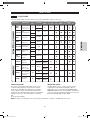
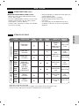
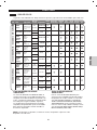
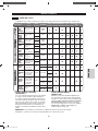
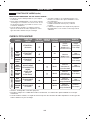
NOTE: Deduct 6 ft. (1.8 m) for each additional elbow. It is not recommended to use more than four 90° elbows.
Selecting and Verifying Duct Length Chart
0 65 feet (19.8 m)
1 55 feet (16.8 m)
2 47 feet (13.7 m)
3 36 feet (11.0 m)
4 28 feet (8.5 m)
0 55 feet (16.8 m)
1 47 feet (13.7 m)
2 41 feet (12.5 m)
3 30 feet (9.1 m)
4 22 feet (6.7 m)
2
1
/2"
(6.35 cm)
4"
(10.2 cm)
4"
(10.2 cm)
Recommended
Only for Short-Run
Installations
Numberof90°Elbows
VentHoodType
Maximumlengthof4”(10.2cm)
diameter rigid metal duct
16
EnGLISH
VENTING THE DRYER
INSTALLATION INSTRUCTIONS
IMPORTANT!
CHECK YOUR EXHAUST SYSTEM FOR
PROBLEMS
Themostcommoncauseofdryerproblemsispoorexhaustventing. Before you install your new dryer, check
the items listed below to make sure you get the best possible performance. This can save you time and money by
reducing cycle times and increasing energy efficiency.
DIRTYORDAMAGEDEXHAUSTDUCTS. Lint builds up in exhaust ducts over time. This decreases the airflow
and makes the dryer work harder. Visually inspect your ducts from both ends and have them cleaned if they have
not been cleaned recently.
WRONGVENTMATERIAL. Check your vent to make sure it is rigid or semi-rigid metal ducting. If your venting is
plastic or flexible foil, have it replace before using the dryer.
RESTRICTEDORDAMAGEDVENTHOOD. Check your vent hood outside. It must be clean and free of lint
buildup. Check the damper and make sure it opens fully and easily.
EXESSIVELYLONGVENT. Measure the length of your exhaust system and count the elbows. Use the chart of
page 16 to see if your duct is too long. If it is too long, have the duct routed to another location that is within the
venting guidelines.
DONOTUSEPLASTICORFOILVENTING. The transition duct from your dryer to the wall must be rigid or semi-
rigid metal ducting. If your old transition duct is plastic or foil, REPLACE IT with semi-rigid metal ducting.
Select the type of vent hood.
Select row that matches the number of elbows required in the dryer duct run.
Look to the right of elbow number for the maximum duct length for your installation. Longer duct length will result
in reduced drying performance, longer dry times and increased energy consumption.
DO NOT exceed maximum length for the duct type and number of elbows used.
1
1
2
2
3
3
4
5
Using the Duct Requirements Chart (below)

17
EnGLISH
INSTALLATION INSTRUCTIONS
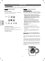
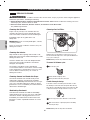
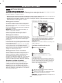
CorrectVenting
Restricted or Blocked Airflow
Avoid long runs or runs with multiple elbows or
bends.
Check for blockages and lint buildup.
Make sure the ductwork is not crushed or
restricted.
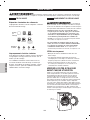
Your dryer features FlowSense
™
, an innovative sensing system that automatically detects
blockages and restrictions in dryer ductwork. Keeping ductwork clean of lint buildup and free of
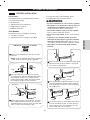
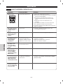
restrictions allows clothes to dry faster and reduces energy use.
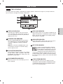
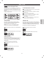
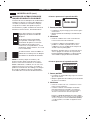
NOTE: When the dryer is first installed, this test should be performed to alert you to any existing
problems with the exhaust duct in your home. However, since the test performed during normal
operation provides more accurate information on the condition of the exhaust duct than does the
installation test, the number of bars displayed during the two tests may not be the same.
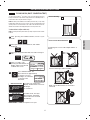
Toactivatetheowcheck(Ductconditiontest):
NOTE:Dryer heating test must be performed before proceeding. Then perform the duct condition
test below:
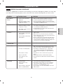
If no bars are shown in the
display, the ductwork is free from
blockages
or restrictions.
If all bars are lit, the dryer
ductwork has a blockage
that needs to be removed
immediately.
IMPORTANT:Do NOT interrupt the test cycle!
THE DUCTWORK IS FREE
FROM BLOCKAGES OR
RESTRICTIONS.
COMPLETED FLOW CHECK
THE DUCTWORK HAS
A BLOCKAGE THAT NEEDS
TO BE REMOVED
IMMEDIATELY.
NEED FLOW CHECK
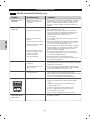
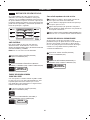
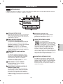
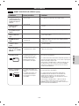
1
5
CUSTOM PGM
*PGM SAVE
OPTION
*LANGUAGE
FLOW CHECK
THIS TEST CHECKS THE CONDITION
OF THE EXHAUST DUCT AT THE TIME
OF INSTALLATION
HIGH
0:02
EST . TIME
REMAINING
FLOW CHECK
0:02
EST . TIME
REMAINING
HIGH
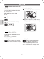
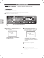
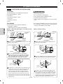
After pressing the POWER ON/OFF, turn the cycle
knob.
2
When pressing the OPTION button, OFF will be
displayed.
3
When pressing CUSTOM PGM, OFF will be change to
ON.
ON I
FLOW CHECK
4
After 3 seconds, or by
pressing the EXIT button, the
display will show the FLOW
CHECK start screen.
Press START/PAUSE. The
dryer will run for approximately
2 minutes to test for
blockages or restrictions
to air flow in the
ductwork.
FLOW CHECK (DUCT CONDITION TEST)

18
EnGLISH
INSTALLATION INSTRUCTIONS
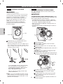
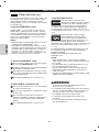
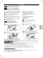
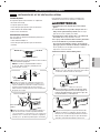
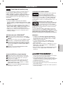
Use an adjustable wrench to turn the leveling
feet. Turn clockwise to raise the dryer or
counterclockwise to lower it. Raise or lower
the leveling feet until dryer is level from
side to side and front to back.
Make sure that all 4 leveling feet are in firm
contact with the floor.
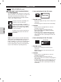
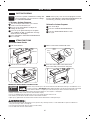
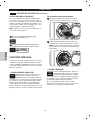
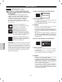
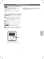
The swing of the dryer door can be reversed to fit your
installation location.
Position the dryer in the final location. Place
a level across the top of the dryer.
Level
Leveling Feet
•Allfourlevelingfeetmust restsolidly on the
floor. Gently push on the top corners of the
dryer to make sure that the dryer does not
rock from corner to corner.
To ensure that the dryer provides optimal drying
performance, it must be level. To minimize
vibration, noise, and unwanted movement, the
floor must be a perfectly level, solid surface.
NOTE:Adjust the leveling feet only as far as
necessary to level the dryer. Extending the
leveling feet more than necessary can cause
the dryer to vibrate.
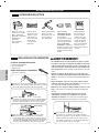
THEDRYERDOORISVERYLARGEANDHEAVY.Failure
to follow the instructions below can result in damage to the
dryer, property damage or personal injury.
•Toavoiddamagetothedryerorthedoor,supportthe
door with a stool or box that fits under the door, or have
an assistant support the weight of the door.
•AlwaysreversethedoorBEFOREstackingthedryeron
top of the washer.
•Avoiddroppingthedoortoavoiddamagetothedooror
the floor.
NOTE:If you are installing the dryer on the
optional pedestal, the dryer leveling feet should
be fully retracted. Use the leveling feet on the
pedestal to level the dryer.
LEVELING THE DRYER
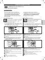
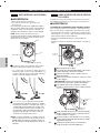
REVERSING THE DOOR SWING
WARNING
•Wearglovesduringinstallation.
•Failuretofollowtheseinstructionscanresultininjury.
w
WARNING
w
Hinge
Screws
Door
Latch
Latch Screws
Open the dryer door.
Using a Phillips screwdriver, remove the 2 latch
screws and the latch.
Remove the 2 blank screws, one each above and
below the latch.
While supporting the weight of the door, remove the 2
hinge screws.
CAUTION: Be sure to support the weight of the door
before removing the hinge screws.
Carefully turn the door upside down and reinstall it on
the opposite side using the screws removed in step 4.
Hinge
Screws
Latch
Screws
Install the door latch in the opening on the side
from which the door was removed using the
screws from step 2.
Install the blank screws from step 3 in the holes
above and below the latch where the door was
originally mounted.
Test the door for proper operation and make sure
it latches properly.
1
1
2
3
4
5
6
7
8

19
EnGLISH
HOW TO USE
Following are instructions for starting and using your new dryer. Please refer to specific sections
of this manual for more detailed information. ImportantWarning:Toreducetheriskoffire,
electricshock,orinjurytopersons,readthisentiremanual,includingtheImportantSafety
Instructions, before operating this dryer.
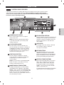
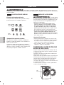
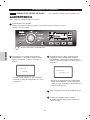
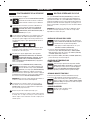
CYCLE SETTING BUTTONS
Use these buttons to select the desired cycle
settings for the selected cycle. The current
settings are shown in the display. Press the
button for that option to view and select
other settings.
5
POWER ON/OFF BUTTON
Press to turn the dryer ON. Press again to
turn the dryer OFF.
NOTE: Pressing the ON/OFF button during
a cycle will cancel that cycle and any load
settings will be lost.
CYCLE SELECTOR KNOB
Turn this knob to select the desired cycle.
Once the desired cycle has been selected, the
standard presets will be shown in the display.
On MANUAL DRY cycles, these settings can
be adjusted using the cycle settings buttons
anytime before starting the cycle.
1
2
START/PAUSE BUTTON
Press this button to START the selected
cycle. If the dryer is running, use this button
to PAUSE the cycle without losing the
current settings.
NOTE: If you do not press the START/PAUSE
button to resume a cycle within 4 minutes,
the dryer automatically turns off.
3
MORE TIME/LESS TIME BUTTONS
To adjust the drying time, use these buttons
with MANUAL DRY, TIME DRY, and STEAM
FRESH
™
cycles, as well as the REDUCE STATIC
and EASY IRON options. Press the MORE TIME
button to increase the selected manual cycle
time by a minute; press LESS TIME to decrease
the cycle time by a minute.
4
2
1
3
4
7
6
8
5
6
LCD DISPLAY
The display shows the settings, estimated
time remaining, options, and status
messages for your dryer.
8
HELPFUL STEAM FUNCTIONS
New steam technology allows you to inject
fabrics with a swirling jet of hot steam to
refresh clothes, reduce static, and make
ironing easier. Simply select the STEAM
FRESH
™
cycle, or you can add a STEAM
option to selected cycles.
For detailed information about the individual
options, please see the following pages.
7
OPTION BUTTONS
The OPTION buttons allow you to select
additional cycle options. Certain buttons
feature a special function (see the following
pages for details) that can be activated by
pressing and holding that option button.
CONTROL PANEL FEATURES

20
EnGLISH
HOW TO USE
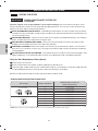
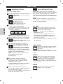
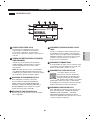
TEMP. CONTROL
Adjusts the temperature setting from ULTRA
LOW to HIGH. This allows precise care of
your fabrics
and garments. Press the TEMP.
CONTROL button repeatedly to scroll through available
settings.
TIME DRY
Allows you to manually select the drying
time, from 20 to 60 minutes, in 10-minute
increments. Use this for small loads or to
remove wrinkles. Use the MORE TIME/
LESS TIME buttons to add or reduce the drying time in
1-minute increments.
BEEPER
Adjusts the volume of the end-of-cycle
beeper, or turns off the beeper.
DRY LEVEL
Selects the level of dryness for the cycle.
Press the DRY LEVEL button repeatedly to
scroll through available settings.
• Thisoptionisonlyavailablewith
SENSOR DRY cycles.
•Thedryerwillautomaticallyadjustthecycletime.
Selecting VERY DRY or MORE DRY will increase
the cycle time, while LESS DRY or DAMP DRY will
decrease the cycle time.
•UseaLESSDRYorDAMPDRYsettingforitemsthat
you wish to iron.
DRY
LEVEL
TEMP.
CONTROL
TIME
DRY
BEEPER
SENSOR DRY cycles have preset settings that are
selected automatically and cannot be changed. MANUAL
DRY cycles have default settings, but you may also
customize the settings using the cycle setting buttons.
Press the button for that option to view and select other
settings.
NOTE:To protect your garments, not every dryness
level, temperature, or option is available with every cycle.
See the Cycle Guide for details.
Press the ON/OFF button to turn on the dryer. The
lights around the cycle selector knob
will illuminate.
Turn the cycle selector knob to the desired cycle.
The display will show
the preset Dry Level,
Temperature, Time, and
Option settings for that cycle.
If you would like to change the settings
for that cycle, press the option button(s)
to display additional settings for that option. Press the
button again to cycle through the settings until the de-
sired setting is highlighted.
NOTE:To protect your garments, not every dry level, tem-
perature, or option is available with every cycle.
1
2
3
Select any additional cycle options, such as ANTIBAC-
TERIAL, DAMP DRY BEEP, FLOW CHECK,
WRINKLE CARE, or RACK DRY by pressing
the button for that option.
4
Once you have loaded the dryer:
Press the START/PAUSE button to begin the
cycle. The display will change, and
the dryer will display the estimated
(SENSOR DRY) or set time (MANUAL
DRY) remaining and start tumbling. To
pause the cycle at any time, open the dryer door
or press PAUSE. To resume the cycle where it was
stopped, press START/PAUSE again.
NOTE: If the dryer has been stopped for more
than 8 minutes, the dryer will turn
off automatically.
5
When the load is finished, the beeper (if
set) will sound. If you have set the WRINKLE
CARE option, the dryer will tumble the load
periodically for up to 3 hours.
To prevent wrinkling, remove items from the dryer
immediately after the end of the cycle.
6
Always clean the lint filter after every cycle.
To clean, pull the lint filter straight up and roll any
lint off the filter with your fingers.
Do not rinse or wash the filter to remove lint. Push
the lint filter firmly back into place.
7
DRY
LEVEL
TEMP.
CONTROL
TIME
DRY
BEEPER
OPTION
*LANGUAGE
OPERATING THE Dryer CYCLE SETTING BUTTONS
Page is loading ...
Page is loading ...
Page is loading ...
Page is loading ...
Page is loading ...
Page is loading ...
Page is loading ...
Page is loading ...
Page is loading ...
Page is loading ...
Page is loading ...
Page is loading ...
Page is loading ...
Page is loading ...
Page is loading ...
Page is loading ...
Page is loading ...
Page is loading ...
Page is loading ...
Page is loading ...
Page is loading ...
Page is loading ...
Page is loading ...
Page is loading ...
Page is loading ...
Page is loading ...
Page is loading ...
Page is loading ...
Page is loading ...
Page is loading ...
Page is loading ...
Page is loading ...
Page is loading ...
Page is loading ...
Page is loading ...
Page is loading ...
Page is loading ...
Page is loading ...
Page is loading ...
Page is loading ...
Page is loading ...
Page is loading ...
Page is loading ...
Page is loading ...
Page is loading ...
Page is loading ...
Page is loading ...
Page is loading ...
Page is loading ...
Page is loading ...
Page is loading ...
Page is loading ...
Page is loading ...
Page is loading ...
Page is loading ...
Page is loading ...
Page is loading ...
Page is loading ...
Page is loading ...
Page is loading ...
Page is loading ...
Page is loading ...
Page is loading ...
Page is loading ...
Page is loading ...
Page is loading ...
Page is loading ...
Page is loading ...
Page is loading ...
Page is loading ...
Page is loading ...
Page is loading ...
Page is loading ...
Page is loading ...
Page is loading ...
Page is loading ...
Page is loading ...
Page is loading ...
Page is loading ...
Page is loading ...
Page is loading ...
Page is loading ...
Page is loading ...
Page is loading ...
Page is loading ...
Page is loading ...
Page is loading ...
Page is loading ...
Page is loading ...
Page is loading ...
Page is loading ...
Page is loading ...
Page is loading ...
Page is loading ...
Page is loading ...
Page is loading ...
Page is loading ...
Page is loading ...
Page is loading ...
Page is loading ...
Page is loading ...
Page is loading ...
Page is loading ...
Page is loading ...
-
 1
1
-
 2
2
-
 3
3
-
 4
4
-
 5
5
-
 6
6
-
 7
7
-
 8
8
-
 9
9
-
 10
10
-
 11
11
-
 12
12
-
 13
13
-
 14
14
-
 15
15
-
 16
16
-
 17
17
-
 18
18
-
 19
19
-
 20
20
-
 21
21
-
 22
22
-
 23
23
-
 24
24
-
 25
25
-
 26
26
-
 27
27
-
 28
28
-
 29
29
-
 30
30
-
 31
31
-
 32
32
-
 33
33
-
 34
34
-
 35
35
-
 36
36
-
 37
37
-
 38
38
-
 39
39
-
 40
40
-
 41
41
-
 42
42
-
 43
43
-
 44
44
-
 45
45
-
 46
46
-
 47
47
-
 48
48
-
 49
49
-
 50
50
-
 51
51
-
 52
52
-
 53
53
-
 54
54
-
 55
55
-
 56
56
-
 57
57
-
 58
58
-
 59
59
-
 60
60
-
 61
61
-
 62
62
-
 63
63
-
 64
64
-
 65
65
-
 66
66
-
 67
67
-
 68
68
-
 69
69
-
 70
70
-
 71
71
-
 72
72
-
 73
73
-
 74
74
-
 75
75
-
 76
76
-
 77
77
-
 78
78
-
 79
79
-
 80
80
-
 81
81
-
 82
82
-
 83
83
-
 84
84
-
 85
85
-
 86
86
-
 87
87
-
 88
88
-
 89
89
-
 90
90
-
 91
91
-
 92
92
-
 93
93
-
 94
94
-
 95
95
-
 96
96
-
 97
97
-
 98
98
-
 99
99
-
 100
100
-
 101
101
-
 102
102
-
 103
103
-
 104
104
-
 105
105
-
 106
106
-
 107
107
-
 108
108
-
 109
109
-
 110
110
-
 111
111
-
 112
112
-
 113
113
-
 114
114
-
 115
115
-
 116
116
-
 117
117
-
 118
118
-
 119
119
-
 120
120
-
 121
121
-
 122
122
-
 123
123
-
 124
124


Kenmore 796.8099 Use & Care Manual And Installation Instructions
- Category
- Electric laundry dryers
- Type
- Use & Care Manual And Installation Instructions
- This manual is also suitable for
Ask a question and I''ll find the answer in the document
Finding information in a document is now easier with AI
in other languages
- français: Kenmore 796.8099
- español: Kenmore 796.8099
Related papers
-
LG 796.8077 Serie Owner's manual
-
-
-
Kenmore 796.8172 User manual
-
 Kenmore Elite 79682192900 Owner's manual
-
 Kenmore Elite 79691028900 Owner's manual
-
-
-
-


Other documents
-
-
LG DLEX3250V User guide
-
IKEA AA-338731-2 User manual
-
-
-
-
LG DLGX4371W Owner's manual
-
 Kenmore Elite 79691549110 Owner's manual
-
LG DLGX3876V Owner's manual
-
LG TDN1653S Owner's manual
