
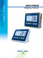
User's Guide
IND231/IND236
Weighing Terminal

IND231/IND236
Weighing Terminal
Essential Services for Dependable Performance of Your IND231/IND236 Weighing Terminal
Congratulations on choosing the quality and precision of METTLER TOLEDO. Proper use of your
new equipment according to this Manual and regular calibration and maintenance by our factory-
trained service team ensures dependable and accurate operation, protecting your investment.
Contact us about a service agreement tailored to your needs and budget. Further information is
available at www.mt.com/service
.
There are several important ways to ensure you maximize the performance of your investment:
1.
Register your product
: We invite you to register your product at
www.mt.com/productregistration so we can contact you about enhancements, updates and
important notifications concerning your product.
2.
Contact METTLER TOLEDO for service
: The value of a measurement is proportional to its
accuracy – an out of specification scale can diminish quality, reduce profits and increase
liability. Timely service from METTLER TOLEDO will ensure accuracy and optimize uptime and
equipment life.
a.
Installation, Configuration, Integration and Training
: Our service representatives are factory-
trained, weighing equipment experts. We make certain that your weighing equipment is
ready for production in a cost effective and timely fashion and that personnel are trained for
success.
b.
Initial Calibration Documentation
: The installation environment and application
requirements are unique for every industrial scale so performance must be tested and
certified. Our calibration services and certificates document accuracy to ensure production
quality and provide a quality system record of performance.
c.
Periodic Calibration Maintenance
: A Calibration Service Agreement provides on-going
confidence in your weighing process and documentation of compliance with requirements.
We offer a variety of service plans that are scheduled to meet your needs and designed to
fit your budget.

© METTLER TOLEDO 2013
No part of this manual may be reproduced or transmitted in any form or by any
means, electronic or mechanical, including photocopying and recording, for any
purpose without the express written permission of METTLER TOLEDO.
U.S. Government Restricted Rights: This documentation is furnished with
Restricted Rights.
Copyright 2013 METTLER TOLEDO. This documentation contains proprietary
information of METTLER TOLEDO. It may not be copied in whole or in part
without the express written consent of METTLER TOLEDO.
METTLER TOLEDO reserves the right to make refinements or changes to the
product or manual without notice.
COPYRIGHT
METTLER TOLEDO
®
is a registered trademark of Mettler-Toledo, LLC. All other
brand or product names are trademarks or registered trademarks of their
respective companies.
METTLER TOLEDO RESERVES THE RIGHT TO MAKE REFINEMENTS OR
CHANGES WITHOUT NOTICE.
FCC Notice
This device complies with Part 15 of the FCC Rules and the Radio Interference
Requirements of the Canadian Department of Communications. Operation is
subject to the following conditions: (1) this device may not cause harmful
interference, and (2) this device must accept any interference received, including
interference that may cause undesired operation.
This equipment has been tested and found to comply with the limits for a Class
A digital device, pursuant to Part 15 of FCC Rules. These limits are designed to
provide reasonable protection against harmful interference when the equipment
is operated in a commercial environment. This equipment generates, uses, and
can radiate radio frequency energy and, if not installed and used in accordance
with the instruction manual, may cause harmful interference to radio
communications. Operation of this equipment in a residential area is likely to
cause harmful interference in which case the user will be required to correct the
interference at his or her expense.
Declaration of Conformity is located on the documentation CD.

RoHS Compliance Statement.
The majority of our products fall within categories 8 and 9. Those categories
currently do not fall within the scope of the Directive 2002/95/EG (RoHS) of
January 27, 2003. If our products are intended for use in other products
which themselves fall within the scope of the RoHS Directive, compliance
requirements have to be separately negotiated contractually.
Those products which fall within categories 1-7 and 10 will be in compliance
with the EU RoHS Directive from no later than July 1, 2006.
If it is not possible for technical reasons to replace any non-RoHS-compliant
substances in any of the above products as required, we plan to inform our
customers in a timely manner
Statement regarding harmful substances
We do not make direct use of harmful materials such as asbestos, radioactive
substances or arsenic compounds. However, we purchase components from
third party suppliers, which may contain some of these substances in very small
quantities.

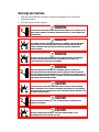
Warnings and Cautions
• READ this manual BEFORE operating or servicing this equipment and FOLLOW these
instructions carefully.
• SAVE this manual for future reference.
WARNING
FOR CONTINUED PROTECTION AGAINST SHOCK HAZARD CONNECT THE AC VERSION OF THE
IND231/IND236 TERMINAL TO PROPERLY GROUNDED OUTLET ONLY. DO NOT REMOVE THE
GROUND PRONG.
WARNING
ONLY PERMIT QUALIFIED PERSONNEL TO SERVICE THE TERMINAL. EXERCISE CARE WHEN
MAKING CHECKS, TESTS AND ADJUSTMENTS THAT MUST BE MADE WITH POWER ON.
FAILING TO OBSERVE THESE PRECAUTIONS CAN RESULT IN BODILY HARM AND/OR
PROPERTY DAMAGE.
WARNING
THE IND231/IND236 IS NOT DESIGNED FOR USE IN AREAS CLASSIFIED AS HAZARDOUS
BECAUSE OF COMBUSTIBLE OR EXPLOSIVE ATMOSPHERES. DO NOT INSTALL AN
IND231/IND236 INTO AN EXPLOSIVE ENVIRONMENT.
WARNING
WHEN THIS EQUIPMENT IS INCLUDED AS A COMPONENT PART OF A SYSTEM, THE
RESULTING DESIGN MUST BE REVIEWED BY QUALIFIED PERSONNEL WHO ARE FAMILIAR
WITH THE CONSTRUCTION AND OPERATION OF ALL COMPONENTS IN THE SYSTEM AND THE
POTENTIAL HAZARDS INVOLVED. FAILURE TO OBSERVE THIS PRECAUTION COULD RESULT IN
BODILY HARM AND/OR PROPERTY DAMAGE.
CAUTION
THE NiMH BATTERY USED IN THIS DEVICE MAY PRESENT A RISK OF FIRE OR CHEMICAL
BURN IF MISTREATED. DO NOT CRUSH, DISASSEMBLE, HEAT ABOVE 60°C OR INCINERATE.
REPLACE BATTERY WITH 30044650 ONLY. USE OF ANOTHER BATTERY MAY PRESENT A RISK
OF BURN, FIRE OR EXPLOSION.
CAUTION
USE CAUTION WHEN TESTING THE BATTERY. A LARGE AMOUNT OF CURRENT MAY BE
PRESENT IN THE BATTERY.
CAUTION
DISPOSE OF USED BATTERY PROMPTLY. KEEP AWAY FROM CHILDREN. DO NOT
DISASSEMBLE AND DO NOT DISPOSE OF IN FIRE.

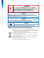
Warnings and Cautions
CAUTION
BEFORE CONNECTING/DISCONNECTING ANY INTERNAL ELECTRONIC COMPONENTS OR
INTERCONNECTING WIRING BETWEEN ELECTRONIC EQUIPMENT ALWAYS REMOVE POWER
AND WAIT AT LEAST THIRTY (30) SECONDS BEFORE ANY CONNECTIONS OR
DISCONNECTIONS ARE MADE. FAILURE TO OBSERVE THESE PRECAUTIONS COULD RESULT IN
DAMAGE TO OR DESTRUCTION OF THE EQUIPMENT AND/OR BODILY HARM.
NOTICE
DO NOT ATTEMPT TO CHARGE THE Ni-MH BATTERY IF THE BATTERY TEMPERATURE IS BELOW 0°C (32°F).
CHARGING IS NOT POSSIBLE AT OR BELOW THIS TEMPERATURE. DO NOT OPERATE THE BATTERY CHARGER
OUTSIDE ITS TEMPERATURE RANGE OF 0°C (32°F) TO 40°C (104°F).
NOTICE
TO AVOID DAMAGE TO THE PCB OR LOAD CELL, REMOVE POWER FROM THE IND231/IND236 TERMINAL AND
WAIT AT LEAST 30 SECONDS BEFORE CONNECTING OR DISCONNECTING ANY HARNESS.
NOTICE
OBSERVE PRECAUTIONS FOR HANDLING ELECTROSTATIC SENSITIVE DEVICES.
Disposal of Electrical and Electronic Equipment
In conformance with the European Directive 2002/96/EC on Waste Electrical and Electronic
Equipment (WEEE) this device may not be disposed of in domestic waste. This also applies
to countries outside the EU, per their specific requirements.
Please dispose of this product in accordance with local regulations at the collecting point
specified for electrical and electronic equipment.
If you have any questions, please contact the responsible authority or the distributor from
which you purchased this device.
Should this device be passed on to other parties (for private or professional use), the
content of this regulation must also be related.
Thank you for your contribution to environmental protection.

Document 30094013 | Revision 00 | 08/2013
METTLER TOLEDO IND231/IND236 Terminal User's Guide
1
Contents
1 Introduction ................................................................................. 1-1
1.1. IND231/IND236 Overview ............................................................. 1-1
1.1.1. Standard Features ............................................................................................... 1-1
1.1.2. IND231/IND236 Terminal Types ........................................................................... 1-2
1.2. Use in Hazardous Areas ................................................................. 1-2
1.3. Specifications ............................................................................... 1-2
1.4. Model Identification ....................................................................... 1-4
1.5. Inspection and Contents Checklist ................................................... 1-5
1.6. Physical Dimensions ..................................................................... 1-5
1.7. Main PCB .................................................................................... 1-6
1.8. Scale Bases ................................................................................. 1-7
1.9. Options ........................................................................................ 1-7
1.9.1. Isolated Serial interface RS232/RS422/RS485 ........................................................ 1-7
1.9.2. Discrete I/O ......................................................................................................... 1-7
1.9.3. USB ................................................................................................................... 1-7
1.10. Display and Keyboard ................................................................... 1-8
1.10.1. Display Layout .................................................................................................... 1-8
1.10.2. Front Panel Keys ................................................................................................. 1-8
2 Operation .................................................................................... 2-1
2.1. Overview ...................................................................................... 2-1
2.2. Keypad Operation and Display Elements .......................................... 2-1
2.2.1. Keypad Operation ................................................................................................ 2-1
2.2.2. Display Elements ................................................................................................ 2-3
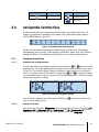
2.3. Configurable Function Keys ............................................................ 2-5
2.3.1. Configuring Function Keys .................................................................................... 2-5
2.3.2. Function keys assignment .................................................................................... 2-6
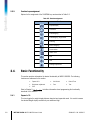
2.4. Basic Functionality ........................................................................ 2-6
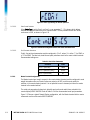
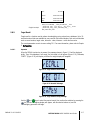
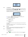
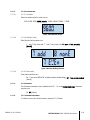
2.4.1. Expand x 10 ....................................................................................................... 2-6
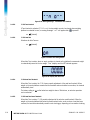
2.4.2. Unit Switching ..................................................................................................... 2-7
2.4.3. Date and Time .................................................................................................... 2-8
2.4.4. Backlight Adjustment ........................................................................................... 2-8
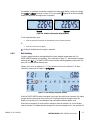
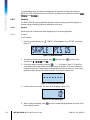
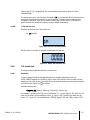
2.4.5. Zero ................................................................................................................... 2-8
2.4.6. Tare ................................................................................................................... 2-9
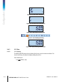
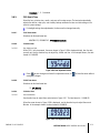
2.4.7. Print ................................................................................................................. 2-10
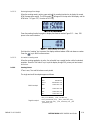
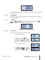
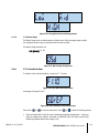
2.5. Remote Display Functionality ........................................................ 2-11
2.5.1. Introduction ...................................................................................................... 2-11
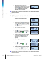
2.5.2. Setup ............................................................................................................... 2-11
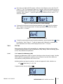
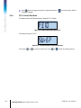
2.5.3. Remote Display Operation .................................................................................. 2-13

2
METTLER TOLEDO IND231/IND236 Terminal User's Guide
30094013 | 00 | 08/2013
Contents
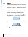
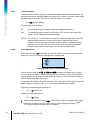
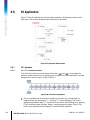
2.6. Applications ............................................................................... 2-14
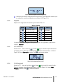
2.6.1. Checkweighing.................................................................................................. 2-14
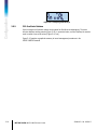
2.6.2. Target Recall ..................................................................................................... 2-17
2.6.3. Counting .......................................................................................................... 2-18
2.6.4. Animal Weighing ............................................................................................... 2-20
2.6.5. Accumulation .................................................................................................... 2-21
3 Configuration .............................................................................. 3-1
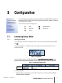
3.1. Accessing Setup Mode ................................................................... 3-1
3.1.1. Entering Setup Mode ............................................................................................ 3-1
3.1.2. Exiting Setup Mode .............................................................................................. 3-2
3.1.3. Setup Menu Navigation ........................................................................................ 3-3
3.2. Setup Menu Structure ..................................................................... 3-5
3.2.1. Main setup menu ................................................................................................ 3-5
3.2.2. Configurable function keys ................................................................................... 3-5
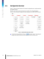
3.3. Configuration Overview .................................................................. 3-6
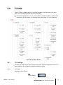
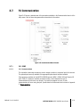
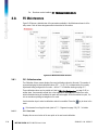
3.4. F1 Scale ...................................................................................... 3-7
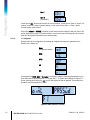
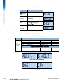
3.4.1. F1.1 Scale type ................................................................................................... 3-7
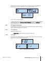
3.4.2. F1.2 Capacity and Increment ................................................................................ 3-9
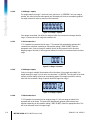
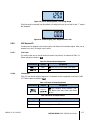
3.4.3. F1.3 Calibration ................................................................................................ 3-11
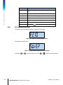
3.4.4. F1.4 Zero ......................................................................................................... 3-13
3.4.5. F1.5 Tare ......................................................................................................... 3-15
3.4.6. F1.6 Second Units ............................................................................................. 3-17
3.4.7. F1.7 Filter ......................................................................................................... 3-18
3.4.8. F1.10 Scale Block Reset .................................................................................... 3-19
3.5. F2 Application ............................................................................ 3-20
3.5.1. F2.1 Operation .................................................................................................. 3-20
3.5.2. F2.2 Over/Under Database ................................................................................. 3-22
3.5.3. F2.3 Counting ................................................................................................... 3-26
3.5.4. F2.4 Animal Weighing ....................................................................................... 3-26
3.5.5. F2.5 Discrete I/O ............................................................................................... 3-27
3.5.6. F2.10 Application Block Reset ............................................................................ 3-28
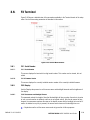
3.6. F3 Terminal ................................................................................ 3-29
3.6.1. F3.1 Serial Number ........................................................................................... 3-29
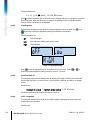
3.6.2. F3.2 Display ..................................................................................................... 3-29
3.6.3. F3.3 Date & Time .............................................................................................. 3-31
3.6.4. F3.10 Terminal Block Reset ................................................................................ 3-32
3.7. F4 Communication ..................................................................... 3-33
3.7.1. F4.1 COM1....................................................................................................... 3-33
3.7.2. F4.2 – COM 2 ................................................................................................... 3-36
3.8. F5 Maintenance .......................................................................... 3-38
3.8.1. F5.1 Calibration values ...................................................................................... 3-38
3.8.2. F5.2 – Statistics ................................................................................................ 3-39
3.8.3. F5.3 Keyboard Test ........................................................................................... 3-39

30094013 | 00 | 08/2013
METTLER TOLEDO IND231/IND236 Terminal User's Guide
3
3.8.4. F5.4 Display Test .............................................................................................. 3-40
3.8.5. F5.5 Serial Test ................................................................................................. 3-40
3.8.6. F5.6 Discrete I/O Test ........................................................................................ 3-41
3.8.7. F5.7 Raw counts ............................................................................................... 3-41
3.8.8. F5.8 Print Configuration ..................................................................................... 3-42
3.8.9. F5.10 Reset All to Factory Default Settings ........................................................... 3-42
4 Service and Maintenance ............................................................. 4-1
4.1. Cleaning and Maintenance ............................................................. 4-1
4.2. Service ........................................................................................ 4-1
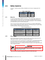
4.3. Battery Operation .......................................................................... 4-2
4.3.1. Battery Use ......................................................................................................... 4-2
4.3.2. Battery Disposal .................................................................................................. 4-2
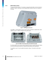
4.3.3. Battery Status Icon ............................................................................................... 4-3
4.3.4. Alkaline Battery Version ........................................................................................ 4-4
4.3.5. Rechargeable NiMH Battery Pack Version ............................................................... 4-5
4.4. Troubleshooting ............................................................................ 4-5
4.4.1. Battery Power...................................................................................................... 4-5
4.4.2. Problem Diagnosis .............................................................................................. 4-6
4.4.3. Error Codes and Error Messages ........................................................................... 4-6
4.4.4. Scale Statistics .................................................................................................... 4-8
4.5. Connection to InSite™ ................................................................... 4-8
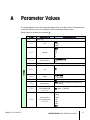
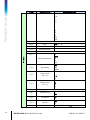
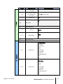
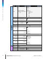
A Parameter Values ........................................................................ A-1
B Communications .......................................................................... B-1
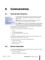
B.1. Serial Interface Parameters ............................................................. B-1
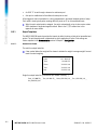
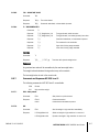
B.2. Demand Output Mode.................................................................... B-1
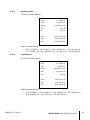
B.2.1. Output Templates ................................................................................................ B-2
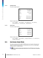
B.3. Continuous Output Mode ................................................................ B-4
B.3.1. Standard Continuous Output ................................................................................. B-5
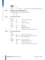
B.4. CTPZ ........................................................................................... B-7
B.5. Standard Interface Command Set (SICS) Protocol .............................. B-7
B.5.1. Version Number of the MT-SICS ............................................................................. B-8
B.5.2. Command Formats .............................................................................................. B-8
B.5.3. Response Formats ............................................................................................... B-9
B.5.4. Tips for the Programmer ..................................................................................... B-10
B.5.5. Commands and Responses MT-SICS Level 0 ....................................................... B-11
B.5.6. Commands and Responses MT-SICS Level 1 ....................................................... B-15
B.5.7. Commands and Responses MT-SICS Level 2 ....................................................... B-17
B.5.8. Commands and Responses MT-SICS Level 3 ....................................................... B-18
C GEO Codes .................................................................................. C-1
C.1. Original Site Calibration ................................................................. C-1

4
METTLER TOLEDO IND231/IND236 Terminal User's Guide
30094013 | 00 | 08/2013
Contents
C.2. New Site GEO Code Adjustment ...................................................... C-1

30094013 | 00 | 08/2013
METTLER TOLEDO IND231/IND236 User's Guide
1-1
This chapter covers
• Overview of IND231/IND236
• Use in Hazardous Areas
• Specifications
• Model Identification
• Inspection and Contents
Checklist
• Physical Dimensions
• Main PCB
• Scale Bases
• Options
• Display and Keyboard
1 Introduction
The IND231/IND236 industrial scale terminal provides a compact yet flexible
solution for a variety of weighing needs. Available as either AC powered for
stationary applications or battery-powered for portable applications, this terminal is
at home in virtually any industrial environment.
Both 2mv/V and 3mv/V load cells are supported without the need for any
configuration change. The IND231/IND236 delivers precision measurement data
from grams to kilograms in a single, cost effective package.
Standard applications include basic weighing, animal weighing, Over/Under
checkweighing, counting and accumulation. Pre-defined application-specific print
templates including date and time stamp, provide transmission of weighing
transaction information to printers and PC software applications.
1.1. IND231/IND236 Overview
1.1.1. Standard Features
• Easy to handle plastic enclosure design for the IND231, rugged stainless steel enclosure for
the IND236
• Supports one analog load cell platform with up to four 350Ω load cells
• Can be used as a remote display to show weight from a separate main terminal
• Large seven segment LCD display with white backlight and graphic icons for clear readability
in varying light conditions
• Powered by either 85–264 V AC or internal battery pack
• One standard serial port (COM1) for asynchronous, bidirectional communication
• Support for one of the following option boards:
COM2 electrically isolated RS232, RS422 and RS485 serial Interface
USB device Interface for connection to a PC
Discrete I/O interface
• Front panel key access to basic weighing functions – zero, tare, clear, configurable function
and print
• Selectable primary unit of measure including grams, kilograms, pounds and ounces
• Selectable second unit of measure including grams, kilograms, pounds and ounces

1-2
METTLER TOLEDO IND231/IND236 User's Guide
30094013 | 00 | 08/2013
Introduction
• Backup and restore of configuration and calibration settings, using InSite
®
SL tool
• Automatic shutoff and backlight timeout features to help conserve energy and extend battery
life when using the battery powered version
1.1.2. IND231/IND236 Terminal Types
The terminal is available in the following four versions:
• IND231plastic housing, AC power (also designed for use with AA size alkaline cells)
• IND231plastic housing, Rechargeable Ni-MH Battery power
• IND236 stainless steel housing, AC power
• IND236 stainless steel, Rechargeable Ni-MH battery power
1.2. Use in Hazardous Areas
WARNING
DO NOT USE THE IND231/IND236 TERMINAL IN AREAS CLASSIFIED AS HAZARDOUS
BECAUSE OF COMBUSTIBLE OR EXPLOSIVE ATMOSPHERES. CONTACT AN AUTHORIZED
METTLER TOLEDO REPRESENTATIVE FOR INFORMATION ABOUT HAZARDOUS AREA
APPLICATIONS.
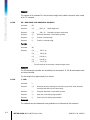
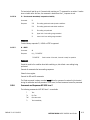
1.3. Specifications
The IND231 and IND236 terminal conforms to the specifications listed in Table 1-1.
Table 1-1: Terminal Specifications
Specifications IND231 IND236
Enclosure Type
Plastic, configurable as desk top or
column/wall mount enclosure
Stainless steel, configurable as desk
top or column/wall mount enclosure
Product Dimensions
(w × h × d)
220 mm x 150 mm x 102 mm
(8.66 in. x 5.90 in. x 4.02 in.)
220 mm x 150 mm x 93.3 mm
(8.66 in. x 5.90 in. x 3.67 in.)
Shipping Dimensions
(w × h × d)
350 mm x 220 mm x 195 mm
(13.78 in. x 8.66 in. x 7.68 in.)
Product Weight
AC Version: 1.2 kg (2.6 lb)
Battery Version: 1.5 kg (3.3lb)
AC Version: 2.2 kg (4.9 lb)
Battery Version: 2.5 kg (5.5 lb)
Shipping Weight
2.0 kg 3.0 kg
Environmental Protection
IP54 IP66/67
Operating Environment
Operating temperature range: -10 °C to +40 °C
Storage temperature range: -20 °C to +60
°C
Relative Humidity: 10-95%, non-condensing.

30094013 | 00 | 08/2013
METTLER TOLEDO IND231/IND236 User's Guide
1-3
Specifications IND231 IND236
Hazardous Areas
The terminal cannot be operated in areas classified as Hazardous because of
combustible or explosive atmospheres in those areas. Contact an authorized
METTLER TOLEDO representative for information about hazardous area
applications.
Power
AC version: Operates at 85–264 VAC, 49–61 Hz and includes a power cord
configured for the country of use.
Battery version :
Six "AA" size alkaline batteries or
NiMH rechargeable battery pack
(about 120hrs for one load cell)
Battery version :
NiMH rechargeable battery (about
120hrs for one load cell)
Display
40 mm height character, seven digits seven segment LCD with white backlight
including weight display, weight units, gross/net indication and symbols for
motion, center of zero and variable applications
Weight Display
Maximum displayed resolution of 30,000 divisions
Scale Types
Analog load cells
Number of Cells
Up to four 350 ohm load cells(2 or 3 mV/V)
Number of Scales
One
Analog/Digital Update Rate
Internal analog: 80 Hz
Load Cell Excitation Voltage
5 VDC
Minimum Sensitivity
0.5 µV/e
Keypad
Seven keys: Zero, Tare, Clear, On/Off, Print, F1 & F2 (configurable)
Communication options
Serial Interfaces
Standard: One serial port (COM1) RS-232, 1,200 to 115,200 baud
Optional isolated serial port: (COM2) RS-232/422/485, 1,200 to
115,200 baud
Discrete I/O Interface
Optional Discrete I/O port: 2 inputs/4 outputs
USB Interface
Optional USB device port
Protocol
Serial Inputs: ASCII commands for CTPZ (Clear, Tare, Print, Zero), SICS
(most level 0 and level 1 commands)
Application
Zero, Tare, Print, X10, Date & Time, Basic weighing, Animal weighing,
Counting with APW enhancement, Over/Under checkweighing with 10 records
database, Accumulation, Remote display

1-4
METTLER TOLEDO IND231/IND236 User's Guide
30094013 | 00 | 08/2013
Introduction
Specifications IND231 IND236
Approvals
Weights and Measures,
USA:
NTEP Class III/IIIL - 10,000d; Cert. #13-049,
Canada:
Class III - 10,000d; Class IIIHD - 20,000d,
Europe:
Class III, 2 x 3000e and 6000e; TC8351, T5976
OIML:
Class III, 2 x 3000e and 6000e; R76/2006-NL1-13.06
Product Safety
UL, cUL, CE
Accessories
Wall mount/column mount bracket; desk bracket.
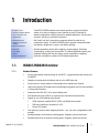
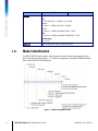
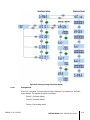
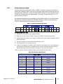
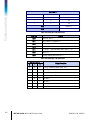
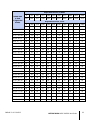
1.4. Model Identification
The IND231/IND236 model number, factory number and serial number are located on the data
plate of the terminal. Refer to Figure 1-1 to verify the configuration of the IND231/IND236 terminal
when it left the METTLER TOLEDO factory.
Figure 1-1: IND231 Configuration Chart

30094013 | 00 | 08/2013
METTLER TOLEDO IND231/IND236 User's Guide
1-5
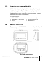
1.5. Inspection and Contents Checklist
Verify the contents and inspect the package immediately upon delivery. If the shipping container is
damaged, check for internal damage and file a freight claim with the carrier if necessary. If the
container is not damaged, remove the terminal from its protective package, noting how it was
packed, and inspect each component for damage.
If shipping the terminal is required, it is best to use the original shipping container. The terminal
must be packed correctly to ensure its safe transportation.
The package should include:
• IND231 or IND236 Terminal • User manual (or resource CD)
• Installation Manual (or Safety Instructions) • Battery Pack (battery version only)
• Power cord • Mounting brackets (1)
• Bag of miscellaneous parts
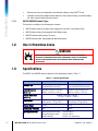
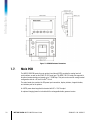
1.6. Physical Dimensions
The physical dimensions of the IND231/IND236 enclosure are shown in Figure 1-2 and Figure 1-3
in mm and [inches].
Figure 1-2: IND231 Enclosure Dimensions

1-6
METTLER TOLEDO IND231/IND236 User's Guide
30094013 | 00 | 08/2013
Introduction
Figure 1-3: IND236 Enclosure Dimensions
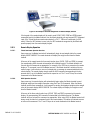
1.7. Main PCB
The IND231/IND236 terminal’s main printed circuit board (PCB) provides the analog load cell
scale interface, as well as the COM1 RS-232 serial port. The COM1 RS-232 serial port supports bi-
directional communications at speeds up to 115200 bps. This port can be used for saving terminal
configuration data to a PC via the InSite
®
SL tool.
The main board also contains the DC power input connection, display interface, keypad interface,
and interface port for the options.
An AC/DC power board supplies the terminal with DC +12V/1A output.
An optional charging board is included with the rechargeable battery powered version.

30094013 | 00 | 08/2013
METTLER TOLEDO IND231/IND236 User's Guide
1-7
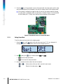
1.8. Scale Bases
The IND231/IND236 terminal supports analog scale bases and provides 5 volts of excitation to
drive analog load cells. Up to four 350Ω load cells can be powered by the terminal.
A four- or six-wire load cell connection is provided, with sense lines to help maintain accuracy as
the load cell cable resistance changes due to variations in temperature.
1.9. Options
Three kinds of option interface can be mounted on COM2. The connection pin specifications are
printed on the PCB.
The following options are available for the IND231 and IND236.
1.9.1. Isolated Serial interface RS232/RS422/RS485
This optional port provides RS-232 and RS-422/485 communication which can be configured in
setup. The port is bidirectional and can be used for various functions such as print, auto print,
Toledo continuous output or SICS communications.
The COM2 port is galvanically isolated for both RS-232 and RS-485, to provide surge voltage
protection.
The RS-485 connection can be used as an RS-422 transmit only, when sending continuous output
to a scoreboard or remote display.
The interface RS422/485 is required for data transmission with higher baud rate over longer
distances up to 500 m.
Communication settings can be configured in the terminal setup menu.
1.9.2. Discrete I/O
The discrete I/O interface option provides four dry-contact relay outputs. The relay contacts will
switch up to 30 volts DC or 250 volts AC at 1A.
The two inputs are switch selectable as either active (for simple pushbutton control) or passive (for
connection to devices that supply their own power for the inputs).
1.9.3. USB
The USB port provided is a UART-USB device bridge acting as a virtual COM port, and is used for
communication of serial data to devices such as a PC. The port is bidirectional and can be
configured for various functions such as print, auto print, Toledo continuous output or SICS
communications. USB external keyboards and bar code scanners are not supported.

1-8
METTLER TOLEDO IND231/IND236 User's Guide
30094013 | 00 | 08/2013
Introduction
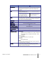
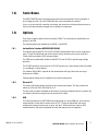
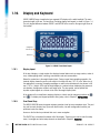
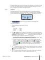
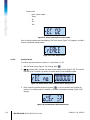
1.10. Display and Keyboard
IND231/IND236 uses a transflective type segment LCD display with a white backlight. The main
character height is 40 mm. The front panel, including display and keypad, is shown in Figure 1-4.
The only keypad difference between IND231 and IND236 is the name on the upper right corner of
the terminal.
Figure 1-4: IND231 Front Panel Layout
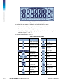
1.10.1. Display Layout
At the top of display, a single system line displays terminal status such as range number, center of
zero, checkweighing status, counting, accumulation and auto accumulation.
Below the system line is the weight display block. During normal, basic weighing operation, the
terminal display shows the gross or net weight in the larger 40 mm (1.57 in.) size. When one of
the applications is running, prompting messages or menu index characters are also shown in 40
mm (1.57 in.) height. At the right of weight display is a vertical column displaying the gross and
net symbols, average piece symbol, and weight units. The star symbol, minus symbol and
dynamic symbol appear in a column to the left of the weight display block.
At the bottom of the normal basic weighing display is a block used for assigning functions to
and
. For display and keypad operation during setup, refer to Chapter 3,
Configuration.
1.10.2. Front Panel Keys
The IND231/IND236 terminal operator interface provides a total of seven membrane keys. The print
key and five scale function keys (three with fixed function, two with configurable functions) are
positioned under the display.
Arrows on the first four keys indicate their use in menu navigation.
The ON/OFF key is located at the bottom left of the display. These keys are used to enter the setup
menu, to navigate and select setup elements as described in Chapter 2,
Operation
.
Print Key
ON/OFF key
Configurable
Function keys

30094013 | 00 | 08/2013
METTLER TOLEDO IND231/IND236 User's Guide
2-1
This chapter covers
• Overview
• Keypad Operation and Display
Elements
• Configurable Function Keys
• Basic Functionality
• Remote Display Functionality
• Applications
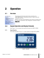
2 Operation
2.1. Overview
This chapter provides information about the basic functionality of the
IND231/IND236 terminal, including display operation, keypad functions and
configurable function keys.
Operation of the terminal varies depending on which functions are enabled, and on
the configuration of parameters in setup. Configuration is described in Chapter 3,
Configuration.
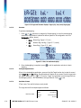
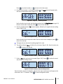
2.2. Keypad Operation and Display Elements
Refer to Figure 2-1 for an overview of the layout of the front panel of the IND231/ IND236.
2.2.1. Keypad Operation
The front panel keys shown in Figure 2-1 are used to operate and configure IND231/IND236.
Figure 2-1: Front panel

2-2
METTLER TOLEDO IND231/IND236 User's Guide
30094013 | 00 | 08/2013
Operation
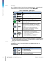
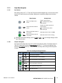
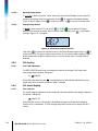
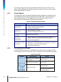
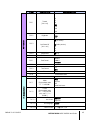
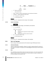
2.2.1.1. Function Keys
Table 2-1 explains the function of each of the keys during normal operation. Further details about
keypad functions while in the setup menu are provided in Chapter 3,
Configuration
.
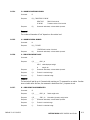
Table 2-1: Keypad Functions – Normal Operation
Keys Function Explanation
FUNCTION 1
Function varies depending on what is selected in the
menu.
FUNCTION 2
Function varies depending on what is selected in the
menu.
ZERO
Used to reset the displayed weight to Zero.
TARE
Captures current weight as a tare value, and sets
terminal to Net mode.
CLEAR
When in the net weight mode, press CLEAR to clear the
current tare value; the display will revert to the gross
weight value. CLEAR operates regardless of motion on
the scale.
Note that once the tare value has been cleared, it
cannot be recalled. The complete tare process as
described above must be performed.
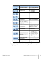
Transfer /
Print / Enter
Key
• Send information to the RS232 interface
• Access to setup menu by long pressing the icon
• Used for printing application
• Press the ENTER key to accept the item or
selection and move to the next display.
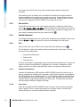
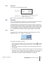
The ZERO and TARE functions will not operate when there is motion on the scale. If one of these
keys is pressed while the scale is in motion, the command will be retained for the programmed number
of seconds while the terminal waits for no-motion. If a no-motion condition is not detected within the
timeout period, the request is cancelled and discarded.
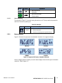
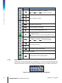
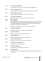
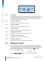
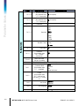
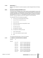
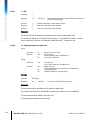
2.2.1.2. Direction Keys
The direction keys in Table 2-2 are used for changing focus between on-screen items, for
confirming a selection.
Table 2-2: Direction Keys
Keys Function Explanation
LEFT
• Move the focus left
• Back to previous menu
RIGHT
• Move the focus right
• Access to the next submenu
Page is loading ...
Page is loading ...
Page is loading ...
Page is loading ...
Page is loading ...
Page is loading ...
Page is loading ...
Page is loading ...
Page is loading ...
Page is loading ...
Page is loading ...
Page is loading ...
Page is loading ...
Page is loading ...
Page is loading ...
Page is loading ...
Page is loading ...
Page is loading ...
Page is loading ...
Page is loading ...
Page is loading ...
Page is loading ...
Page is loading ...
Page is loading ...
Page is loading ...
Page is loading ...
Page is loading ...
Page is loading ...
Page is loading ...
Page is loading ...
Page is loading ...
Page is loading ...
Page is loading ...
Page is loading ...
Page is loading ...
Page is loading ...
Page is loading ...
Page is loading ...
Page is loading ...
Page is loading ...
Page is loading ...
Page is loading ...
Page is loading ...
Page is loading ...
Page is loading ...
Page is loading ...
Page is loading ...
Page is loading ...
Page is loading ...
Page is loading ...
Page is loading ...
Page is loading ...
Page is loading ...
Page is loading ...
Page is loading ...
Page is loading ...
Page is loading ...
Page is loading ...
Page is loading ...
Page is loading ...
Page is loading ...
Page is loading ...
Page is loading ...
Page is loading ...
Page is loading ...
Page is loading ...
Page is loading ...
Page is loading ...
Page is loading ...
Page is loading ...
Page is loading ...
Page is loading ...
Page is loading ...
Page is loading ...
Page is loading ...
Page is loading ...
Page is loading ...
Page is loading ...
Page is loading ...
Page is loading ...
Page is loading ...
Page is loading ...
Page is loading ...
Page is loading ...
Page is loading ...
Page is loading ...
Page is loading ...
Page is loading ...
Page is loading ...
Page is loading ...
Page is loading ...
Page is loading ...
Page is loading ...
Page is loading ...
Page is loading ...
Page is loading ...
Page is loading ...
Page is loading ...
Page is loading ...
Page is loading ...
Page is loading ...
Page is loading ...
-
 1
1
-
 2
2
-
 3
3
-
 4
4
-
 5
5
-
 6
6
-
 7
7
-
 8
8
-
 9
9
-
 10
10
-
 11
11
-
 12
12
-
 13
13
-
 14
14
-
 15
15
-
 16
16
-
 17
17
-
 18
18
-
 19
19
-
 20
20
-
 21
21
-
 22
22
-
 23
23
-
 24
24
-
 25
25
-
 26
26
-
 27
27
-
 28
28
-
 29
29
-
 30
30
-
 31
31
-
 32
32
-
 33
33
-
 34
34
-
 35
35
-
 36
36
-
 37
37
-
 38
38
-
 39
39
-
 40
40
-
 41
41
-
 42
42
-
 43
43
-
 44
44
-
 45
45
-
 46
46
-
 47
47
-
 48
48
-
 49
49
-
 50
50
-
 51
51
-
 52
52
-
 53
53
-
 54
54
-
 55
55
-
 56
56
-
 57
57
-
 58
58
-
 59
59
-
 60
60
-
 61
61
-
 62
62
-
 63
63
-
 64
64
-
 65
65
-
 66
66
-
 67
67
-
 68
68
-
 69
69
-
 70
70
-
 71
71
-
 72
72
-
 73
73
-
 74
74
-
 75
75
-
 76
76
-
 77
77
-
 78
78
-
 79
79
-
 80
80
-
 81
81
-
 82
82
-
 83
83
-
 84
84
-
 85
85
-
 86
86
-
 87
87
-
 88
88
-
 89
89
-
 90
90
-
 91
91
-
 92
92
-
 93
93
-
 94
94
-
 95
95
-
 96
96
-
 97
97
-
 98
98
-
 99
99
-
 100
100
-
 101
101
-
 102
102
-
 103
103
-
 104
104
-
 105
105
-
 106
106
-
 107
107
-
 108
108
-
 109
109
-
 110
110
-
 111
111
-
 112
112
-
 113
113
-
 114
114
-
 115
115
-
 116
116
-
 117
117
-
 118
118
-
 119
119
-
 120
120
-
 121
121
-
 122
122


Ask a question and I''ll find the answer in the document
Finding information in a document is now easier with AI
Related papers
Other documents
-
Detecto DR660 Calibration Operating instructions
-
-
Mettler Toledo IND231-IND236 Operating instructions
-
-
Hardy HIBSD User manual
-
-
Ohaus A71P15DTNUS User manual
-
Cardinal PS-6 Owner's manual
-
Adam Equipment AE403 User manual
-