Page is loading ...

Owner's Manual
P80153001F-Date: 01/10/2003
Important Note: This grill is manufactured to
exact specifications. Model SS48055 LP is
certified for use with LP gas and Model SS48055
NG is certified for use with Natural Gas. You
can not convert this grill from one fuel type
to the other. For your safety, conversion kits
are not available. Any attempt to convert your
grill will void your warranty.
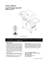
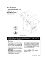
Liquid Propane Gas Grill
MODEL SS48055 LP
Natural Gas Grill
MODEL SS48055 NG
WARNING:
Read this Owner's Manual carefully and be sure
your gas grill is properly assembled, installed and
maintained. Follow all leak check procedures
carefully in this manual prior to grill operation. Do
this even if the grill was store assembled.
Failure to follow these instructions could result in
serious bodily injury and/or property damage.
This grill is intended for outdoor use only and is
not intended to be installed in or on recreational
vehicles or boats.
!
Note to Installer: Leave this Owner's Manual
with the consumer after delivery and/or installation.
Customer Service: If you have questions about assembly or grill operation, or if there are damaged
or missing parts when you unpack this unit from the shipping boxes, call us 8:00am - 5:00 pm EST,
Monday through Friday at: 1-800-667-7313
MODEL SS48055 LP SHOWN
Note to Consumer: Leave this Owner's Manual
in a convenient place for future reference.
Imported by S.R. Potten Ltd/Ltée
1645-50th AVE. LACHINE, QUEBEC, CANADA
H8T 3C8
TEL:514-631-4995
TOLL FREE:1-800-667-7313
FAX:514-636-8185

2
Warranty ..................................................... 2
Safety Instructions ..................................... 2
Natural Gas Safety Instructions............... 4
Pre-Assembly Instructions..............................5
Hardware, Parts Diagram and Lists ..... 6
Assembly Instructions ............................... 10
Lighting Instructions .................................. 16
Back Burner, Rotisserie Instructions....... 18
Cleaning and Maintenance Instructions .... 19
Frequently Asked Questions.................. 21
Cooking Instructions ................................ 22
Cooking Guide and Recipes................ 23
Read These Safety Instructions
Grill Installation Codes
This gas grill must be installed in accordance with all
local codes. In areas without local codes, follow the
latest edition of the National Fuel Gas Code ANSI Z223.
1. In Canada, installation must conform to standard
CAN/CGA 1b149.1 or 1-b149.2 (Installation Code for
Gas Burning Appliances and Equipment) and all local
codes.
Correct LP Gas Tank Use
LP gas grill models are designed for use with a standard
20 lb. Liquid Propane Gas (LP gas) tank, not included
with grill box. Never connect your gas grill to an LP
gas tank that exceeds this capacity. A tank of
approximately 12 inches in diameter by 18-1/2 inches
high is the maximum size LP gas tank to use. You
must use an "OPD" gas tank which offers an
Overfill Prevention Device. This safety feature pre-
vents the tank from being overfilled which can cause
malfunction of the LP gas tank, Regulator and/or grill.
The LP gas tank must be constructed and marked in
accordance with specifications of the U.S. Dept. of
Transportation (DOT). In Canada, the LP gas tank must
meet the Canadian Transportation and Communications
(CTC) specifications. Also be sure to read and follow
all LP gas instructions on the following page.
Patio Chef Warranty
Warranty Restrictions:
• This warranty does not cover surface rust or
natural oxidation.
• This warranty is void if grill is used for commercial
or rental purposes.
• This warranty applies only when the grill is used
in the United States
. This warranty gives you specific legal rights, and
you may also have other rights which vary from
province to province. See back cover for warranty
details.
Full 1-Year Warranty on Grill
For one year from the date of purchase, the Manufacturer
will repair or replace, at their option, any grill part (except
for paint loss, rusting, AA batteries) that is defective
in material or workmanship.
Limited Warranty on Selected Grill Parts
From the date of purchase for the designated time
periods stated below, the Manufacturer will replace the
following grill parts if they are defective in material or
workmanship. Some charges may appply for shipping
and handling.
• Lifetime of the grill: Stainless steel parts
(except for discoloration due to normal use or
excessive heat, and scratches or dents caused
by normal use and improper maintenance).
Aluminum Castings (except for paint loss)
• 5 Years: Cast-iron Burners
• For Warranty Service: Call our Customer Service
Dept. 8:00am - 5:00pm EST, Monday through
Friday at 1-800-667-7313
Table of Contents
1. Shut off gas to the appliance.
2. Extinguish any open flame.
3. Open lid.
4. If odor continues, immediately call your gas
supplier or your fire department.
If you smell gas:
FOR YOUR SAFETY
Do not store or use gasoline or other flammable
vapors and liquids in the vicinity of this or any
other appliance.
An LP gas tank not connected for use shall not
be stored in the vicinity of this or any other
appliance.
1.
2.
FOR YOUR SAFETY
!
WARNING
Combustion byproducts produced when using
this product contain chemicals known to the
State of California to cause cancer, birth
defects, or other reproductive harm.
Failure to comply with these instructions could
result in a fire or explosion that could cause
serious bodily injury, death, or property
damage.
!
WARNING
Your grill will get very hot. Never lean over
the cooking area while using your grill. Do not
touch cooking surfaces, grill housing, grill lid or
any other grill parts while the grill is in operation,
or until the grill has cooled after use.
Failure to comply with these instructions
may result in serious bodily injury.
!
WARNING

3
• Never connect an unregulated LP gas tank to
your gas grill. The gas Regulator assembly
supplied with your gas grill is adjusted to have
an outlet pressure of 11" water column (W.C.)
for connection to an LP gas tank.
• Only use the Regulator and Hose Assembly
supplied with your gas grill. Replacement
Regulators and Hose Assemblies must be
those specified by manufacturer.
• Have your LP gas tank filled by a reputable propane
gas dealer and visually inspected and
re-qualified at each filling.
• Never fill the gas tank beyond 80% full.
Have your propane gas dealer check the release
valve after every filling to ensure that it remains free
of defects.
• Always keep LP gas tanks in upright position.
• Do not store (or use) gasoline or other flammable
vapors and liquids in the vicinity of this gas grill.
• An LP gas tank that is not connected for use must
NOT be stored on bottom shelf inside cabinet or in
the vicinity of this or any other gas grill.
• Do not subject the LP gas tank to excessive heat.
• Never store an LP gas tank indoors. If you
store your gas grill in the garage or other indoor
location, always disconnect the LP gas tank
first, store it safely outside.
• LP gas tanks must be stored outdoors in a
well-ventilated area and out of the reach of
children. Disconnected LP gas tanks must not be
stored in a building, garage or any other enclosed
area.
• When your gas grill is not in use the gas
must be turned off at the LP gas tank.
Proper Placement and Clearance of Grill
Never use your gas grill in a garage, porch, shed,
breezeway or any other enclosed area. Your gas grill is to
be used outdoors only, at least 24 inches from the back
and side of any combustible surface. Your gas grill
should not be placed under any surface that will burn.
Do not obstruct the flow of ventilation air around the
gas grill housing.
This outdoor gas grill is not intended to be installed in
or on recreational vehicles and/or boats.
The LP gas tank has a Shut Off Valve, terminating
in an LP gas supply tank valve outlet, that is
compatible with a Type 1 tank connection device.
The LP gas tank must also have a safety relief
device that has a direct communication with the
vapor space of the tank.
The tank supply system must be arranged for
vapor withdrawal.
The LP gas tank used must have a collar
to protect the tank valve.
1.
2.
3.
• The Regulator and Hose assembly must be
inspected before each use of the grill. If there
is excessive abrasion or wear or if the hose
is cut, it must be replaced prior to the grill
being used again.
• Keep the gas Regulator Hose away from hot
grill surfaces and dripping grease. Avoid
unnecessary twisting of hose. Visually inspect
hose prior to each use for cuts, cracks,
excessive wear or other damage. If the Hose
appears damaged do not use the gas grill, call
our Customer Service Dept. for a replacement,
at 1-800-667-7313.
• Never light your gas grill with the Lid closed
or before checking to insure the Burner Tubes
are fully seated over the Gas Valve Orifices.
• Never allow children to operate your grill. Do
not allow children to play near your grill.
Failure to comply with these instructions
could result in a fire or explosion that could
cause serious bodily injury, death, or prop-
erty damage.
WARNING!
A strong gas smell, or the hissing sound of gas
indicates a serious problem with your gas grill
or the LP gas tank. Failure to immediately follow
the steps listed below could result in a fire or
explosion that could cause serious bodily
injury, death, or property damage.
NOTE: The normal flow of gas through the
Regulator and Hose Assembly can create a
humming sound. A low volume of sound is
perfectly normal and will not interfere with opera-
tion of the grill. If humming sound is loud and
excessive you may need to purge air from the
gas line or reset the Regulator excess gas flow
device. This purging procedure should be done
every time a new LP gas tank is connected to
your grill. For help call the Grill Information
Center.
Customer Service Dept., 8:00am-5:00pm
EST, Monday through Friday at:
1-800-667-7313
• Shut off gas supply to the gas grill.
• Turn the Control Knobs to OFF position.
• Put out any flame with a Class B fire
extinguisher.
• Open Grill Lid.
• Get away from the LP gas tank.
• Do not try to fix the problem yourself.
• If odor continues or you have a fire you cannot
extinguish, call your fire department. Do not call
near the LP gas tank because your telephone is
an electrical device and could create a spark
resulting in fire and/or explosion.
!
WARNING

Natural Gas Safety Instructions
• Your Natural Gas Grill is designed to operate on
Natural Gas only, at a pressure of 7" water column
(W.C.) (1/4 psig or 1.75 kpa), regulated at the
residential meter. Check with your gas utility com-
pany for local gas pressure and with your local
municipality for building code requirements. If your
residential gas line pressure has not been
regulated to 7" W.C., contact your local gas utility
company for professional assistance.
• The gas pressure Regulator supplied with this
appliance must be used. This Regulator is set
for an outlet pressure of 4" W.C.
• It is recommended that a Shut Off Valve be installed
at the gas supply source outdoors. Install at a point
after the gas pipe exits the outside wall and before the
Quick Disconnect Hose, or install it at the point
before the gas line piping enters the ground. See
Figure 1.
• Pipe sealing compound or pipe thread tape resistant
to the action of Natural Gas must be used on all male
pipe threads when making the connection.
• Disconnect your gas grill from fuel source when
the gas supply is being tested at high pressures.
This gas grill and its individual Shut Off Valve must
be disconnected from the gas supply pipe system
during any pressure testing of that system at
pressure in excess of 1/2 psi (3.5kpa).
• Turn off your gas grill when the gas supply is
tested at low pressures. The grill must be
isolated from the gas supply pipe system
by closing its individual Manual Shut Off
Valve during any pressure testing of the gas
supply pipe system at pressures equal to
or less than 1/2 psi (3.5kpa).
• The Quick Disconnect connects to a 3/8 inch
NPT thread from gas source. The Quick
Disconnect fitting is a hand operated device
that automatically shuts off the the flow of
gas from the source when it is disconnected.
• The Quick Disconnect fitting can be installed
horizontally,or pointing downward.DO NOT
install the fitting with the opening pointing
upward because the fitting could collect water
and debris.
• The Dust Covers (plastic plugs) provided with
the Quick Disconnect help keep the open
ends clean while disconnected.
• The outdoor connector must be firmly attached to
a ridged permanent construction.
• The Quick Disconnect MUST BE installed above
ground.
• WARNING: Do not route the 12 foot Quick
Disconnect Hose under a deck. The hose must
be visible and inspected prior to each grill use.
Figure 1
(For Natural Gas Model Only)
If the length of line required does not exceed 50 feet, use
a 5/8" O.D. tube. One size larger should be used for
lengths greater than 50 feet.
Gas piping may be copper tubing, type K or L; polyeth-
ylene plastic tube, with a minimum wall thickness of .
062 inch; or standard weight (schedule 40) steel or
wrought iron pipe.
Copper tubing must be tin-lined if the gas contains more
than 0.3 grams of hydrogen sulfide per 100 cubic feet
of gas.
Plastic tubing is suitable only for outdoor, underground
use.
Gas piping in contact with earth, or any other material
which may corrode the piping, must be protected
against corrosion in an approved manner.
Underground piping must have a minimum of 18"
cover.
All connections and joints must be thoroughly tested
for leaks in accordance with local codes and all listed
procedures in the latest edition of ANSI Z223.1
4
Gas Line Piping
Test Connections
Do not use an open flame to check for gas
leaks. Be sure there are no sparks or open
flames in the area while you check for gas
leaks. This will result in a fire or explosion
which can cause serious bodily injury or
death, and damage to property.
DANGER!
NATURAL GAS SUPPLY
QUICK
DISCONNECT
INSIDE WALL
OUTSIDE WALL
MALE
FITTING
TO NATURAL GAS
REGULATOR
LOCKING GAS
SHUT OFF VALVE
LOCKING
GAS
SHUT OFF
VALVE
Additional
Hardware Not
Included

To reduce the chance of "FLASH-BACK" (see CAU-
TION at left) clean the Burner Tubes and Burners
before fully assembling your grill. Remove the Cotter
Pin from the rear underside of each Burner using a
pair of long nose pliers. Carefully lift each Burner up
and away from the Gas Valve Orifice, then refer to
Figure 1 and perform one of these three cleaning
methods:
Pre-Assembly Instructions
Bend a stiff wire, (a lightweight coat hanger
works well) into a small hook as shown below.
Run the hook through the Burner Tube and
inside the Burner several times to remove any
debris.
Use a Burner Cleaning Brush, or a bottle brush
with a flexible handle. Run the brush through
the Burner Tube and inside the Burner several
times, removing any debris.
Use an air hose to force air through each Burner
Tube. The forced air should pass debris or
obstructions through the Burner and out the
ports.
1.
2.
3.
CAUTION: Spiders and small insects occasionally
spin webs or make nests in the grill burner tubes
during transit and warehousing. These webs can
lead to a gas flow obstruction which could result
in a fire in and around the Burner Tubes. This
type of fire is known as a "FLASH-BACK" and
can cause serious damage to your grill and create
an unsafe operating condition for the user.
Although an obstructed Burner Tube is not the only
cause of "FLASH-BACK", it is the most common
cause.
To reduce the chance of "FLASH-BACK", you
must clean the Burner Tubes before assembling
your grill, and at least once a month in late
summer or early fall when spiders are most active.
Also perform this Burner Tube cleaning procedure
if your grill has not been used for an extended
period of time.
CAUTION: BEWARE OF FLASH-BACK
The location of the Burner Tube with respect
to the Orifice is vital for safe operation. Check
to ensure the Orifice is inside of the Burner Tube
before using your gas grill. See Figure 2. If the
Burner Tube does not fit over the Valve Orifice,
lighting the Burner may cause explosion
and/or fire.
Figure 1
Figure 2
WARNING
!
Tools Required for Assembly
•
•
•
•
•
•
Phillips Head screw driver
Adjustable wrench
Long nose pliers - used to remove the
Cotter Pin when cleaning the Burners
Open-end wrench (included with Hardware
Pack) used to tighten the Casters.
Protective work gloves
Eye protection
GAS VALVE
ORIFICE
CONTROL
KNOB
CROSS
SECTION
OF MANIFOLD
GAS COLLECTOR BOX
ORIFICE
BURNER TUBE
BURNER PORT
BURNER
SPARK ELECTRODE
GAS COLLECTOR BOX
TO CLEAN BURNER TUBE,
INSERT HOOK HERE

Contents for Hardware Pack (Part #P4182A)
Contents for Hardware Pack (Part #P4182A)
Contents for Hardware Pack
Purpose of Component
The following table illustrates a breakdown of the Hardware Pack. It highlights what components
are used in the various stages of assembly.
Ref.
Qty. to use
1/4" x 2 1/2" Phillips Head Screw
1/4" x 1/2" Phillips Head Screw
3/16" x 1/2" Phillips Head Screw
1/4" x 1/2" Phillips Head Screw
3/16" x 3/8" Phillips Head Screw
M5 x 6mm Phillips Head Screw
1/4" x 1/2" Phillips Head Screw
M4 x 10 Self-Tapping Screw
1/4" x 1/2" Phillips Head Screw
1/4" Lock Nut
1/4" x 3/4" Phillips Head Screw
1/4" x 2 1/2" Phillips Head Screw
1/4" Lock Nut
3/16" x 3/8" Phillips Head Screw
3/16" Lock Nut
3/16" x 1/2" Phillips Head Screw
Component
6
A.
B.
C.
B.
D.
J.
B.
E.
B.
F.
H.
A.
F.
D.
G.
C.
8
8
12
2
2
4
8
1
4
4
4
2
2
6
2
2
Attaches Cart Leg to Bottom Shelf
Secures Bowl Brackets to Cart
Secures Side Panel and Rear Panel to Cart
Secures Door Bracket
Secures Door Stop
Secures Door Handle
Secures Side Shelf Bracket to Cart Leg
Secures Lighting Stick
Secure the Grill Bowl onto the Cart
Attaches Side Shelf on the Side Shelf Bracket
Secures Grill Bowl to Cart Leg
Attaches the Trim Plate on the Side Shelf
Attached the NG Regulator on the Left Rear
Leg

7
Contents for Hardware Pack (Part #P4182A)
Contents for Hardware Pack (Part #P4182A)
Contents for Hardware Pack
Actual Size and Quantity of Each Hardware Piece:
A. 1/4" x 2 1/2" Phillips Head Screw - QTY 10
B. 1/4" x 1/2"
Phillips Head Screw
QTY. 22
H. 1/4" X 3/4"
Phillips Head Screw
QTY. 4
F. 1/4" Lock Nut x 6
H. Manual Lighting Stick (scale 1/2) - QTY. 1 J. "AA" Batteries - QTY. 1
K. Door Handle (scale 1/2) - QTY. 2
L. Caster Wrench - QTY. 1
C. 3/16" x 1/2"
Phillips Head Screw
QTY. 12(additional 2 for NG)
D. 3/16" x 3/8"
Phillips Head Screw
QTY. 8
G. 3/16" Lock Nut x 2
E. M4 x 10
Self-Tapping Screw
QTY. 1
Grill Information Center: If you have questions about assembly or grill operation, or if there are
damaged or missing parts when you unpack this unit from the shipping boxes, call us
8:00am - 5:00 pm CST, Monday through Friday at: 1-800-667-7313
J. M5 x 6mm
Phillips Head Screw
QTY. 4
(found in door handles)

SS48055 Parts Diagram
8
Remove all components from both cartons and place within easy reach. Turn the largest carton
upside down and it will provide a comfortable height work surface for grill assembly.
1
2
4
5
6
7
18
31
32
38
40
36
35
43
47
48
53
34
37
41
37
36
35
33
39
54
34
19
10
9
8
42
30
28
27
26
21
25
20
15
14
12
11
13
16
17
22
23
29
24
44
45
46
50
51
52
49
3
55
56
57
57

9
SS48055 Parts List
QTY.REF# PART#DESCRIPTION
1.
2.
3.
4.
5.
6.
7.
8.
9.
10.
11.
12.
13.
14.
15.
16.
17.
18.
19.
20.
21.
22.
23.
24.
25.
26.
27.
28.
29.
30.
31.
32.
33.
34.
35.
36.
37.
38.
39.
40.
41.
42.
43.
44.
45.
46.
47.
48.
49.
50.
51.
52.
53.
54.
1
1
1
1
1
2
3
1
1
1
1
1
1
1
1
3
3
1
1
1
1
3
3
3
1
1
1
1
4
3
1
1
1
1
1
2
2
2
2
1
1
1
1
1
1
1
1
1
4
4
1
1
1
2
2
1
For the repair or replacement parts you need:
Call our Customer Service Dept., 8am - 5pm EST,
Monday through Friday at 1-800-667-7313
To make sure you obtain the correct replacement part
(s) for your gas grill please refer to the parts list on
this page. The following information is required to
insure you receive the correct parts:
1. Model and Serial Number (see CSA label on grill)
2. Part Number
3. Description
4. Quantity of parts needed
Please allow sufficient time to process and ship.
IMPORTANT: Keep this Owner's Manual for
convenient referral and for part replacement.
IMPORTANT: Use only factory authorized parts. The
use of any part that is not factory authorized can
be dangerous. This will also void your warranty.
Lid Plate
Heat Gauge
Name Plate
Lid Handle
Warming Rack
Cooking Grid
Flame Tamer
Grease Draining Tray
Grease Receptacle
Gas Tube
Back Burner Frame
Spark Electrode
Back Burner
Bowl Rear Panel
Burner Bracket
Burner
Gas Collector Box with Electrode
Bowl Side Panel,Left
Bowl Side Panel,Right
Bowl Front Panel
Heat Shield for Control Panel
Electric Wire Set
Gas Valve for Main Burner
Gas Valve for Main Burner(NG)
Gas Valve for Back Burner
Gas Valve for Back Burner(NG)
Gas Manifold
Control Panel
Control Konb Seat
Control Knob(Main Burner)
Control Knob(Back Burner)
AA Battery
Electric Ignitor
Side Shelf,Left
Side Shelf,Right
Shelf Bracket-A
Shelf Bracket-B
Side Panel
Bowl Support Bracket
Shelf Trim Plate,Left
Shelf Trim Plate,Right
Regulator W.Hose(LP)
Rear Panel
Tank Screw
Side Cart Leg,LF
Side Cart Leg,LR
Side Cart Leg,RF
Side Cart Leg,RR
Castor Seat
Castor
Bottom Shelf
Door Bracket
Door Stop
Door Plate
Door Handle
Lighting Stick
QTY.REF# PART#DESCRIPTION
55.
56.
57.
NG Regulator
Connection Hose
Side Shelf Handle
1
1
2
P0013650AA
P00601021A
P00414040N
P00205042B
P01505007B
P01602005B
P01705005E
P02705084B
P02701041A
P03701003A
P03305006H
P02610005B
P02007027D
P00725044A
P02203055A
P02001031E
P02609002B
P00720413C
P00721413C
P00724046C
P03007051B
P02615033A
P03222053B
P03222026B
P03222026B
P32A9D
P05004072B
P02907011S
P03413011A
P03419031B
P03411142H
P05301001A
P02502134C
P01106038B
P01107038B
P01213005A
P01211005A
P01105039B
P01303010B
P07503002A
P07502003A
P03601004A
P07701017A
P06222019B
P00917005B
P00918005B
P00912005B
P00920005B
P04507003A
P05106003D
P01008005C
P03302001C
P05510009E
P04301003A
P00214034B
P05507031E
Y0080007
P03718038A
P00205016B
CSA Label

10
Cart Assembly Instructions
Remove all cart parts, hardware, and Grill Head from
shipping boxes. Raise the Grill Lid and remove all
packed components. Use the parts list to check that
all necessary parts have been included.
Assemble the gas grill on a protective work surface
to avoid scratching grill surfaces. Inspect your grill for
damage as you proceed. Do not assemble or operate
your grill if it appears damaged.
1.
2.
3.
Assembling The Cart
4.
5.
Position bottom shelf with tank toward the left side.
See Figure 1.
Note: The label on the cart legs indicate their
assembly position to the bottom shelf. LF=Left
Front, LR=Left Rear, RF=Rear Front, and RR=
Right Rear. Labels should face inward toward each
other when correctly assembled. Remaining com-
ponents cannot be assembled if leg postions are
incorrect.
Install the four cart legs to the indicated corners
of the bottom shelf using 8 of the 1/4" x 2-1/2"
Phillips Head screws provided. Do not fully tighten
screws.
Screw the 4 Carters into the caster seats in the
bottom of each cart leg. Turn the threaded caster
stem by hand, clockwise unit it stops. Fully tighten.
With the wrench provided. See Figure 2.
Install the two Side Panels and one Rear Panel to
the cart by using 4 of the 3/16" x 1/2" Phillips
Head screws on each panel. Leave rear panel
screws loose. See Figure 2.
Install the Bowl Support Brackets, facing inward, to
cart legs on both side using 8 of the 1/4" x 1/2"
Phillips Head screws . Fully tighten.
A. 1/4" x 2-1/2" Phillips Head Screw x 8
B. 1/4" x 1/2" Phillips Head Screw x 8
C. 3/16" x 1/2" Phillips Head Screw x 12
Figure 1
Figure 2
BOWL SUPPORT
BRACKET
SIDE CART LEG
CASTER
CASTER
SEAT
SIDE PANEL
REAR PANEL

11
8.
6.
7.
Attach the Door Bracket to the low holes in the
front legs with the end tabs pointing upward and
flange to the rear, pointing downward. Use 2 of
1/4" x 1/2" Phillips Head Screws. Do not fully
tighten. See Figure 3.
Attach the Door Stop to the bottom shelf, with
the flange facing the front, using 2 of 5M x 6mm
Phillips Head Screws. Fully tighten. See
Figure 3.
Place doors into the hinge holes of the bottom shelf
and Door Bracket. Push Door Bracket down until
doors are secure and can open and close freely.
Do not full tighten Door Bracket screws. See
Figure 3.
Remove protective film from Doors. Install Door
Handle to Doors using 4 of 3/16" x 3/8" Phillips Head
Screws and washers. See Figure 3.
Attach the 4 Side Shelf Brackets to the top of the
cart legs using 8 of 1/4" x 1/2" Phillips Head
Screws. Be sure the flat side of each bracket faces
outward. Fully tighten. See Figure 4.
9.
10.
Attach lighting stick to the Right Rear Leg, below
side shelf bracket using 1 M4 x 10 self-tapping
screw. See Figure 5.
11.
B. 1/4" x 1/2" Phillips Head Screw x 2
D. 3/16" x 3/8" Phillips Head Screw x 4
B. 1/4" x 1/2" Phillips Head Screw x 8
E. M4 x 10 Self-Tapping Screw x 1
J. M5 x 6mm Phillips Head Screw x 4
Figure 3
Figure 4
Figure 5
LIGHTING
STICK
SIDE SHELF
BRACKET
DOOR HANDLE
DOOR BRACKET
DOOR PLATE

12.
12
13.
Grill Head Assembly
14.
Slide grill head into cart from the front. Align the
2 holes beneath the hang ledge on each side of
the grill bowl with the 2 holes in the Bowl Support
Bracket on the cart. Raise the grill Lid and insert
4 of 1/4" x 1/2" Phillips Head Screws and 1/4"
Nut. See Figure 6.
Place the Side Shelves over the brackets and
cross braces with the wider-spaced shelf holes to
the outside (shelf with trim plate on right side).
Be sure the inside shelf holes align with holes
in Side Shelf Bracket. Using 4 of 1/4" x 3/4"
Phillips Head Screws. Fully tighten. See
Figure 7.
Secure grill head to all cart legs using 2 of 1/
4" x 2-1/2" Phillips Head Screws and 1/4" Nut for
LR and RR legs. See Figure 7.
Fully tighten all leg screw, Rear Panel Screws,
Door Bracket screws and grill head screws.
From the back of the cart, slide the grease draining
tray into the grill head. Place the grease receptacle
into the notches on the bottom of the tray.
Attach trim plate to front left and right shelf by
placing top lip of plate above bottom lip of shelf.
Secure using 4 of 3/16" x 3/8" Phillips Head
Screws and 3/16" Nuts. Fully tighten attach the
trim plate to leg by using 2 of 3/16" x 3/8" Phillips
Head Screws.
15.
16.
17.
B. 1/4" x 1/2" Phillips
Head Screw x 4
F. 1/4" Lock Nut x 4
A. 1/4" x 2-1/2" Phillips Head Screw x 2
H. 1/4" x 3/4" Phillips
Head Screw x 4
F. 1/4" Lock Nut x 2
D. 3/16" x 3/8" Phillips
Head Screw x 6
G. 3/16" Lock Nut x 4
Figure 6
Figure 8
Figure 7
GRILL BOWL
GREASE RECEPTACLE
GREASE DRAINING TRAY
SIDE SHELF
SHELF BRACKET

18.
To install the side shelf handle, remove the bolt
and washer from one side of the handle (cap
remains with handle). From beneath shelf, place
washer onto bolt and into handle. Leave bolt loose
until other side of handle is attached, then fully
tighten both sides. Repeat for other side shelf.
13
19.
Attaches the Regulator Bracket on the Left
Rear leg.Secure using 2 of 3/16" x 1/2"
Phillips head screws.See Figure 10.
C. 3/16" x 1/2" Phillips Head Screw x 2
Regulator Assembly(NG Only)
Figure 9
Figure 10 (Natural Gas only)
Connection
Hose
Natural Gas Regulator
Regulator
Bracket
Left Rear Leg
Side Shelf Handle

Requires and assistant:
Before placing the cooking components into your grill,
insure that the Spark Electrode Tip is properly positioned
within each Gas Collector Box (stainless steel mecha-
nism found at the front between each set of Burners.)
The easiest way to insure this is to perform this Electrode
Check:
14
1. Be sure all Control Knobs are set to "OFF"
and open the Grill Lid.
2. Have an assistant stand behind to the right of
the grill and look down at each Gas Collector
Box. NEVER put your face inside Grill Head.
3. Push Ignition Cap. You should hear a clicking
sound and your assistant should see a small
blue spark within each Gas Collector Box.
If a spark is present the Electrode Tips are
properly positioned.
4. If no spark is seen the Spark Gap shown in
Figure 12 needs to be adjusted as follows:
• Using an adjustable wrench, loosen the inside
Nut just until the Gas Collector Box can be
maneuvered and turned upward.
• The gap between the Spark Electrode Tip and
Spark receiver should be approximately 3/16".
• If the gap is wider than 3/16" use a pair of long
hose pliers and gently squeeze the Gas
Collector Box until the gap is correct.
• Return the Gas Collector Box to its original
horizontal position, secure the inside Nut and try
the Electrode Check again.
5. If no "clicking" sound is heard check the
following common causes. If you need
assistance call our Grill Information Center
at 1-800-667-7313.
• Ignitor AA battery not installed properly.
• Ignitor wires may be loose. Remove the AA
battery, inspect the Ignitor Junction Box
found behind the Control Panel, and connect
any loose wires.
Ignitor Battery Installation - See Figure 11
1. Unscrew the Ignitor Cap located on the Grill Control
Panel and remove the Contact and Spring from the
Ignitor Slot.
2. Place the manufacturer supplied AA battery into the
Ignitor Slot. Be sure to place the positive pole facing
toward you.
3. Place the Spring over the AA battery, then place
the Contact on top of the Spring. Screw the Ignitor
Cap back onto the grill Control Panel.
Grill Information Center: If you have questions about assembly or grill operation, or if there are
damaged or missing parts when you unpack this unit from the shipping boxes, call us
8:00am - 5:00 pm CST, Monday through Friday at: 1-800-667-7313
Electrode Check
Figure 11
Figure 15 - Side View Gas Collector Box
INSIDE
NUT
SPARK
ELECTRODE TIP
SPARK GAP
+
IGNITOR SOLT
CONTRACT
SPRING
AA BATTERY
IGNITOR CAP

15
Congratulations
Your Member's Mark gas grill is now ready for
use. Before the first use and at the beginning
of each season (and whenever a LP gas tank
has been changed):
1.
2.
3.
Read all safety, lighting and operating
instructions.
Check Gas Valve Orifices, Burner Tubes and
Burner Ports for any obstructions.
Perform gas leak check according to
instructions found on page 17 of this
Owner's Manual.
CAUTION: When the appliance is not in use, the
gas must be turned off at the supply tank.
Place the Flame Tamers on the lower ledge above
Burners. See Figure 13. Place 3 of Flame Tamers
onto the Rack.
Place Cooking Grids on the ledge above Flame
Tamers.
Place Warming Rack into the slot on the upper
left and upper right of the grill bowl panels. See
Figure 13.
IMPORTANT: The Grill is not designed for use with
lava rock or briquettes and the use of such items
will void the warranty.
1.
Installing Cooking Components
2.
Connecting A Liquid Propane Gas (LP gas)
Tank To Your Grill
1. Check the Tank Valve to insure it has proper
external mating threads to fit the Hose and
Regulator Assembly provided. (Type 1 connec
tion per ANSI Z21.58a-1998)
2. Inspect the Valve Connection Port and
Regulator assembly. Look for damage or debris.
Remove any debris. Inspect Hose for damage.
Never use damaged or plugged equipment.
3. Hang your filled gas tank on the Tank Hole.
4. Make sure all Burner Valves are in the OFF
position.
5. When connecting the Hose and Regulator
Assembly to the Tank Valve, hand tighten nut
clockwise to a full stop. Do Not use a wrench
to tighten because it could damage the Quick
Coupling Nut and result in a hazardous
condition.
6. Slowly open the tank valve 1/4 to 1/2 open
(counterclockwise). Use a soapy water solution
to check all connections for leaks before
attempting to light your grill. See "Checking for
Gas Leaks" on page 17. If a leak is found,
turn the Tank Valve off and do not use your
grill until the leak is repaired. Do this leak test
even if the grill was store assembled.
Disconnecting A Liquid Propane Gas (LP gas)
Tank From Your Grill
Turn the Burner Valves and LP Gas Tank Valve
to the full OFF position (turn clockwise to
close).
Detach the Hose and Regulator Assembly from
the LP gas Tank Valve by turning the Quick
Coupling Nut counterclockwise.
1.
2.
Figure 14
Figure 13
COOKING GRID
FLAME
TAMERS
These holes are for
Rotisserie Mount-
ing Bracket use
WARMING RACK
TYPE 1
CONNECTION
PER ANSI Z21.
58A-1998
TANK HOLE
To connect A Natural Gas (NG) Grill Refer
to Instructions on page 4.

Set control knobs to OFF and open the LP gas
tank valve slowly until 1/4 to 1/2 open.
Push and turn the LEFT control knob to HIGH.
Immediately press the electric ignitor for 3-4
seconds to light the burner.
If the burner does not light, turn the control knob to
OFF, wait 5 minutes for gas to clear, then retry.
Once the left grill burner is ignited, the adjacent
burner can be lit by simply turning its control knob
to HIGH.
Adjust control knobs to your desired cooking
temperature.
16
Checking For LP Gas
Never test for leaks with a flame. Prior to first use,
at the beginning of each season, or every time your
LP gas tank is changed, you must check for gas leaks.
Follow these four steps:
3.
4.
Apply the soap solution to all gas connections.
If bubbles appear in the soap solution the con-
nections are not properly sealed. Check each
fitting and tighten or repair as necessary.
If you have a gas leak that you cannot repair,
turn off the gas at the source, disconnect fuel line
from your grill and call 1-800-667-7313 or your gas
supplier for repair assistance.
1.
2.
Make a soap solution by mixing one part liquid
detergent and one part water.
Turn the grill Control Knobs to the full OFF
position, then turn the gas ON at source.
Grill Lighting Instructions
Basic Lighting Procedures
Familiarize yourself with the safety guidelines
at the front of this manual. Do not smoke
while lighting grill or checking gas supply
connections.
Be sure the LP gas tank is filled.
Check that the end of each Burner Tube is
properly located over each valve orifice.
Make sure all gas connections are securely
tightened..
Open the Grill Lid.
1.
2.
3.
4.
WARNING
!
• Shut off gas supply to the gas grill.
• Turn the Control Knobs to OFF position.
• Put out any flame with a fire extinguisher.
• Open Grill Lid.
• Get away from the LP gas tank.
• Do not try to fix the problem yourself.
• If odor continues or you have a fire you
cannot extinguish, call your fire department.
Do not call near the LP gas tank because
your telephone is an electrical device and
could create a spark resulting in fire and/
or explosion.
A strong gas smell, or the hissing sound of gas
indicates a serious problem with your gas grill
or the LP gas tank. Failure to immediately follow
the steps listed below could result in a fire or
explosion that could cause serious bodily injury,
death, or property damage.
NOTE: The normal flow of gas through the
regulator and hose assembly can create a
humming nosie. A low volume of nosie is
perfectly normal and will not interfere with
operation of the grill. If humming nosie is
loud and excessive you may need to purge
air from the gas line or reset the regulator
excess gas flow device. This purging
procedure should be done every time a new
LP gas tank is connected to your grill. For
help call the Customer Service Helpline for
assistance.
WARNING
Failure to open Grill Lid during the lighting
procedures could result in a fire or explosion
that could cause serious bodily injury, death,
or property damage.
!
6.
7.
8.
9.
10.
Customer Service Helpline, 8:00am - 5:00
pm EST, Monday through Friday at
1-800-667-7313.
5.
OFF
HIGH
OFF
Open LP
gas tank
PRESS
ELECTRIC
IGNITOR
11.

17
Manually Lighting Your Grill by Match
To light your gas grill by match, insert a match into the
Manual Lighting Stick and follow steps 1 through 6 of the
Basic Lighting Procedures. Then, light the match and
place Manual Lighting Stick through the Lighting Hole on
the right side of the grill. See Figure 19. Turn the nearest
Main Burner Control Knob to the HIGH setting to release
gas. The Burner should light immediately.
To purge air from your gas line and/or reset
the Regulator excess gas flow device:
Opening the tank valve all the way or too quickly is
what triggers the Regulators safety device to shut
down gas flow which prevents excessive gas flow to
your grill. Lighting the Burner farthest from the fuel
source every time will help eliminate air pockets in
the Manifold. This procedure should be done every
time a new LP gas tank is connected to your grill:
Never lean over the grill cooking area while
lighting your gas grill. Keep your face and body
a safe distance (at least 18 inches) from the
Lighting Hole or Burners, when lighting your grill
by match.
WARNING
!
•
•
•
2.
3.
Misalignment of Burner Tubes over Orifices
Correction: Reposition Burner Tubes over Orifices.
Obstruction in gas line
Correction: Remove fuel line from grill. Do not smoke!
Open gas supply for one second to clear any obstruc-
tion from fuel line. Close off gas supply at source and
reconnect fuel line to grill.
Plugged Orifice
Correction: Remove Burners from grill by pulling
Cotter Pin (beneath Burner) using Long nose
pliers. Carefully lift each Burner up and away
from Gas Valve Orifice. Remove the Orifice from
Gas Valve and gently clear any obstruction with
a fine wire. Then reinstall all Orifices, Burners,
Cotter Pins and cooking components.
If an obstruction is suspected in Gas Valves or Gas
Valve Bracket, please call the Customer Service
Dept. at 1-800-667-7313.
Turn gas off at source and turn the Control Knobs
to OFF. Wait at least five minutes for gas to clear,
then retry.
Check gas supply and connections.
Repeat lighting procedure. If your grill still fails to
operate properly, turn the gas off at source, turn the
Control Knobs to OFF, then check the following:
If the grill fails to light properly:
1.
•
•
•
Misalignment of Ignitor on Burner
Correction: Check for proper position of the
Electrode Tip as shown on page 15. The gap
between the Spark Electrode Tip and Spark
Receiver should be approximately 3/16". Ad-
just if necessary following the Electrode Check
procedure on page 15.
Disconnected Ignition Wires
Correction: Inspect the Ignitor Junction Box
found behind the Control Panel. Connect loose
Ignitor wires to Junction Box and try to light
grill.
Weak AA battery
Correction: Unscrew the Ignitor Cap and replace
the battery.
• Shut off gas supply to the gas grill.
• Turn the Control Knobs to OFF position.
• Put out any flame with a Class B fire
extinguisher.
• Open Grill Lid.
• Once the grill has cooled down, clean
the Burner Tubes and Burners accord
ing to the cleaning instructions found on
page 21 in this manual.
Should a "FLASH-BACK" fire occur in/or
around the Burner Tubes, follow the in-
structions below. Failure to comply with
these instructions could result in a fire or
explosion that could cause serious bodily
injury, death, or property damage.
WARNING
!
Figure. 19
Turn all Control Knobs to the OFF position.
Turn off the LP gas tank valve at the tank
valve.
Disconnect Regulator from LP gas tank.
Let unit stand for 5 minutes.
Reconnect Regulator to the LP gas tank.
Open Grill Lid or Side Burner Lid.
Turn the LP gas tank valve on
slowly until
1/4 to 1/2 open.
Light the Burner farthest from fuel source
by turning its Control Knob to IGN then
pushing in the Control Knob. To light the
Side Burner push its Control Knob in and
turn to HIGH.
••
••
•
••
••
•
••
••
•
••
••
•
••
••
•
••
••
•
••
••
•
••
••
•
LIGHTING
HOLE
MANUAL
LIGHTING
STICK
MATCH

Your new grill includes an Infrared Back Burner and a
Rotisserie designed to slowly cook foods that are moist
and flavorful, because the turning food self bastes using
infrared heat. The location of the Back Burner allows the
placement of a basting pan beneath the food to collect
juices and drippings for basting and gravy. To flavor the
contents of the basting pan you may add herbs, onions,
or other spices of your choice. The Rotisserie Burner is
Infrared, which provides intense radiant heat. This intense
heat is magnificent for searing in the natural juices and
nutrients found in quality cuts of meat.
Rotisserie cooking is a slow cooking process and the
maximum temperature you can expect to reach with
the Lid closed is about 325 to 350
P
F.
18
Using your Infrared
Back Burner and Rotisserie
The Rotisserie Motor must be electrically grounded
in accordance with local codes or, in the absence of
local codes, with the National Electric Code, ANSI/
NFPA 70-1990. Keep the Rotisserie Motor electric
cord away from the heated surface of the grill. Do
not operate the Rotisserie with a damaged cord or
plug, or if the Rotisserie malfunctions or has been
damaged in any manner. Call the Grill Information
Center for replacement. The power supply cord has
a 3-prong grounded plug. For your personal safety
do not remove the grounding prong. It must be
plugged into a mating 3-prong grounding type
receptacle, grounded in accordance with the National
Electrical Codes and local codes and ordinances. If
an extension cord is used it must be properly
grounded and suitable for use with Outdoor
Appliances. Keep the extension cord connection dry,
off of the ground and out of the reach of children.
When the Rotisserie Motor is not in use remove and
store in a dry indoor area.
!
Loading The Rotisserie
To load the Skewer begin with the Handle in place, and
slide one of the Meat Holders (Prongs facing away from
the Handle) onto the Skewer. Push the Skewer through
the center of the food, and then slide the second Meat
Holder, (prongs toward the food) onto the Skewer. It is
very important to center and balance the food to be cooked
on the Skewer then push the Meat Holders firmly together.
Tighten the Wing Nuts with pliers. It may also be
necessary to wrap the food with butcher string (never use
plastic or nylon string) to secure any loose portions. Once
the food is secure insert the Skewer into the motor. If
needed, remove the grill Cooking Grids. Place a basting
pan below the food to collect the juices and drippings as
the food cooks. It is normal for the Skewer to flex when
larger cuts of meats are being cooked. Start motor and
cook food with the Lid closed.
Back Burner Lighting Instructions
Note: The location of the Back Burner makes it more
susceptible to winds that will decrease the performance of
your Rotisserie cooking. For this reason you should not
operate the Back Burner during windy weather conditions.
For best results, always Rotisserie cook with the grill Lid
down and the Back Burner Control Knob set to High. Do
not use the main grill Burners when the Back Burner is in
operation.
1. Open the Grill Lid.
2. Set all Control Knobs to OFF and open the LP gas
Tank Valve
slowly until 1/4 to 1/2 open. For Natural
Gas open Shutt Off Valve at source completly.
3. Push and turn the Back Burner Control Knob to IGN
position. Push the Control Knob in to ignite the burner.
4. If the Burner does not light, turn the Control Knob to
OFF, wait 5 minutes for gas to clear, then retry.
5. Once lit, the Back Burner will reach cooking
temperature quickly. The orange/red glow will even out
in about 5 minutes.
6. For best results, always Rotisserie cook with the grill
Lid down and the Back Burner Control Knob set on
HIGH. Do not use the main Burners when the Back
Burner is in operation.
Read All Instructions:
1. Always attach the Rotisserie to the grill first, and
then plug cord into a grounded outlet. To disconnect,
turn Rotisserie "OFF" then remove plug from outlet.
2. Most grill surfaces and accessories are hot during
and after cooking, so use reasonable care around
grill, wear protective mitts and use the Rotisserie
Handle.
3. The use of accessory attachments on the Rotisserie
is not recommended by the manufacture and may
cause injuries.Do not use this appliance for other
than intended use.
4. Never line the bottom of your Grill Bowl with aluminum
foil, sand or any grease absorbent substance.
5. Should a grease fire occur, turn the Burners and gas
off and leave the Lid CLOSED until fire is out.
WARNING
WARNING
Failure to open Grill Lid during the
lighting procedures could result in a fire
or explosion that could cause serious
bodily injury, death, or property damage.
!

Keeping outdoor cooking gas appliance area clear
and free from comustible materials, gasoline and
other flammable vapors and liquids.
As with all appliances, proper care and mainte-
nance will keep your grill in top operating condition
and prolong its life. By following these cleaning
procedures on a timely basis, your grill will stay
clean and work properly with minimum effort.
19
Cleaning The Cooking Grids
Before initial use and as needed, wash your Grids
with a mild detergent and rinse with hot water. For
stubborn food residue use a degreaser and fiber or
brass cleaning brush.
Cleaning The Grease Tray and Receptacle
To reduce the chance of fire, the Grease Draining
Tray, Grease Receptacle and Heat Shield should be
inspected before each grill use. Remove grease
(a plastic spatula works well) and wash Grease Tray
and Receptacle with a mild soap and warm water
solution.
Cleaning the Flame Tamers
To reduce the chance of flare-ups, Flame Tamers
should be cleaned whenever food or grease drip-
pings accumulate. Brush off Flame Tamers with a
fiber type brush and turn over to allow the burner
heat to burn off any stuborn food residue. The
Ceramic Flame Tamers work equally well on
either side.
Cleaning and Maintenance
Annual Cleaning of The Grill Interior
Use a fiber or brass cleaning brush to clean the
interior Grill Bowl, Cooking Grids, Flame Tamers and
grease containers. On porcelain finished parts never
use a wire brush or metal scraper which can scratch
or chip the porcelain finish and promote rusting.
Check eachSpark Electrode, adjusting as needed.
The space between the Spark Electrode Tip and Spark
Receiver should be approximately 3/16".
Replace the Burners and adjust the gas collector
box. The edge of the collector box should be
overlapping the Burner Port.
Replace Flame Tamers and the Cooking Grids.
Reconnect the gas source and observe the Burner
flame for correct operation.
8.
9.
11.
10.
CAUTION:
Be sure your grill is OFF and cool before cleaning.
1. Turn all Control Knobs to the full OFF position.
2. Turn the LP gas Tank Valve to the full OFF position.
3. Detach the LP gas Regulator assembly from your gas
grill or disconnect the Quick Disconnect Hose from the
gas source.
4. Remove and clean the Flame Tamers, Cooking
Grids, and Grill Burners.
Exterior Stainless Steel Surfaces:
Weathering and high heat can cause a stainless
steel grill Lid to turn tan in color. This is not to be
confused with rust and is not a product defect. Ma-
chine oils used in the manufacturing process of
stainless steel as well as cooking oils and a dirty
grill Lid can also encourage discoloration if the Lid
is not cleaned prior to grill use.
1. Shut off gas supply at source and disconnect
fuel line from Gas Valve Manifold. Protect fuel
line fitting.
2. Use a Stainless Steel Cleaner and soft cloth to
remove residual adhesive and oils from the in
side and outside of your grill Lid. Never use
abrasive cleaners or scrubbers. In addition to
the initial cleaning, routine cleaning to remove
dirt, grease and oils will help discourage Lid
dis
coloration.
Cover each gas Valve Orifice with aluminum foil.
Brush the inside and bottom of the grill with a
brass wire brush or fiber cleaning pad, and wash
with a mild soap and warm water solution. Rinse
thoroughly and let dry.
Remove aluminum foil from Orifices and check
each Orifice for obstruction.
5.
6.
7.
Grill Information Center: If you have questions about assembly or grill operation, or if there are damaged
or missing parts when you unpack this unit from the shipping boxes, call us 8:00am - 5:00 pm CST, Monday
through Friday at:
1-800-677-7313

20
Regardless of which Burner cleaning procedure you
use, we recommend you also complete the
following steps to help prolong Burner life.
1.
2.
3.
Use a wire brush to clean the entire outer
surface of each Burner until free of food residue
and dirt.
Clean any clogged ports with a stiff wire, such
as an open paper clip.
Inspect each Burner for damage (cracks or
holes) and if such damage is found, order and
install a new Burner. After installation, check to
insure that the Gas Valve Orifices are correctly
placed inside the ends of the Burner Tubes.
Also check the position of your Spark
Electrode.
Figure 1
Figure 2
The location of the Burner Tube with respect
to the Orifice is vital for safe operation.
Check to ensure the Orifice is inside of the
Burner Tube before using your gas grill. See
Figure 2. If the burner tube does not fit over
the Valve Orifice, lighting the Burner may
cause explosion and/or fire.
WARNING
!
Bend a stiff wire, (a lightweight coat
hanger works well) into a small hook as
shown below. Run the hook through the
Burner Tube and inside the Burner several
times to remove any debris.
Use a Burner Cleaning Brush or a bottle
brush with a flexible handle. Run the brush
through the Burner Tube and inside the
Burner several times, removing any debris.
Use an air hose to force air through each
Burner Tube. The forced air should pass
debris or obstructions through the Burner
and out the ports.
Cleaning The Burner Tubes and Burner Ports
To reduce the chance of "FLASH-BACK" you must
clean the Burner Tubes at least once a month in late
summer or early fall when spiders are most active or
when your grill has not been used for an extended
period of time.
Turn all Control Knobs to the full OFF position.
Turn the LP gas Tank Valve to the full OFF position.
Detach the LP gas Hose and Regulator Assem-
bly from your gas grill or disconnect the Quick
Disconnect Hose from the Natural Gas source.
Remove the Cooking Grids, Flame Tamers, and
Grease Trays from your grill.
Remove the Cotter Pin from the rear underside of each
Burner using a pair of long nose pliers.
Carefully lift each Burner up and away from the
gas Valve Orifice.
Refer to Figure 1 and perform one of these
three cleaning methods:
1.
2.
3.
4.
5.
6.
7.
•
•
•
ORIFICE
BURNER TUBE
BURNER PORT
BURNER
SPARK ELECTRODE
GAS COLLECTOR BOX
TO CLEAN BURNER TUBE,
INSERT HOOK HERE
GAS VALVE
ORIFICE
CONTROL
KNOB
CROSS
SECTION
OF MANIFOLD
GAS COLLECTOR BOX
SPARK ELECTRODE
/