
Instructions pour l'installation...................................3-4
Instructies voor het installeren.................................5-6
Installationsanleitungen............................................7-8
Instructions for installation.....................................9-10
Istruzioni per l'installazione...................................11-12
Page is loading ...
Page is loading ...
Page is loading ...
Page is loading ...
Page is loading ...
Page is loading ...

7
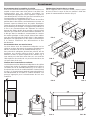
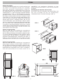
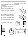
Built-in Installation
Built in installation
For correct operation of the oven built into a kitchen unit or
other housing section, the latter must be suitable.
The characteristics of the housing section and instructions
for fitting in and assembling are given below (Fig. 1- 2).
Protection against contact with electrical parts, in
compliance with current regulations, must be ensured by
correct building-in of the appliance.
All parts which guarantee protection, even any covering
panel (for example if an appliance is located at the end or
beginning of the modular units), must be fixed in such a
way that it cannot be removed without tools. It should be
noted that heat-resistant glues (90°C) must be used to bond
together the layers of plastic material and veneered wood
in housing units for built-in appliances.
Unsuitable plastic materials or glues that are not heat-
resistant are the cause of warping and ungluing.
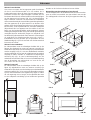
Fitting onto base unit
The housing section must have the dimensions shown in
the figures and be fitted with supports allowing efficient
circulation of cooling air (Fig.3).
Suitable air intakes (Fig. 4) should be provided for efficient
ventilation on the bottom front part and the top part of the
appliance: bottom inlet of at least 200 cm², top outlet of at
least 60 cm² for 60cm (90 cm² ovens for 90cm ovens).
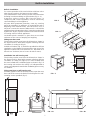
Installation into tall housing unit
The housing section must have the dimensions shown in
the figures and be fitted with supports allowing efficient
circulation of cooling air (Fig.10), It is also essential that
the oven is fitted with a ventilation pipe as shown in fig. 5. If
the housing unit reaches the ceiling, it is indispensable to
connect an adequate channel to the ventilation pipe to convey
air outdoors.
Fixing onto base or tall housing unit
Insert the appliance into the housing section; open the oven
door and fix the oven to the kitchen unit using the four self-
screwing screws provided (fig. 6).
FIG.. 3 FIG.. 4
FIG.. 5 FIG.. 6A
447 mm
78
78
min. 550 mm
3 mm
52
472 mm
480 mm
860 mm
22 mm
895 mm
525 mm
469 mm
840 mm
575 / 585 mm
560 mm
22 mm
545 mm
550 mm
25 mm
595 mm
595 mm
7,5 mm
FIG.. 1
FIG.. 2
min. 45 mm.
A
FIG.. 6B

8
This appliance meets the following CE standards:
DBT 73/23/CEE modified by 93/68/CEE
CEM 89/336/CEE
Before installing the appliance, the meter must be checked
to verify the conditions for the delivery of the available
electrical power (number of phases, voltage, maximum
power) which must be compatible with the needs of the
Scholtès appliance to be installed.
There are two ways to connect the oven during
installation:
- by using an electrical outlet
- or by using a connection panel.
In both cases, refer to the connection diagrams for the
minimum diameters of the wires and the calibration of the
protective components according to the type of connection.
If the installation is done using a connection panel, an
omnipolar switchgear with a minimum gap between
contacts of 3 mm must be installed upstream from the
connection of the appliance.
We recommend that you use a power cord that is long
enough to allow the removal of the oven for maintenance
operations. Use only cables of H05VV-F/H05VV-R quality
equipped with a plug that complies with the regulations of
the country where the appliance is installed.
The plug must be accessible.
Before any maintenance or repair operation, including
replacing the light bulb, you must first disconnect the
appliance.
It is hazardous to operate an appliance that has not
been properly earthed.
Important: After connecting the appliance to the flexible
cable, tighten all the screws on the terminal plate
Electrical Connection
Cookers with a three-pole power supply cable are designed
to operate with alternated current at the supply frequency
and voltage indicated on the data plate (on the front of the
oven dashboard). The earthing conductor of the cable is
the yellow-green conductor.
Connecting the power supply cable to the mains
The appliance must be directly connected to the mains using
an omnipolar circuit-breaker with a minimum contact
opening of 3 mm installed between the appliance and the
mains, suitable for the load indicated and complying with
current directives (the earthing wire must not be interrupted
by the circuit-breaker). The power supply cable must be
positioned so that it does not exceed 50°C more than room
temperature at any point of its length. Before making the
connection check that:
• the limiter valve and the home system can support the
appliance load (see data plate);
• the power supply system has an efficient earthing
connection which complies with the provisions of current
regulations;
• the socket or omnipoar circuit-breaker is easily
accessible once the cooker has been installed.
FAILURE TO OBSERVE THE ACCIDENT-PREVENTION
REGULATIONS RELIEVES THE MANUFACTURER OF ALL
LIABILITY.
Important: the wires in the mains lead are coloured in
accordance with the following code:
Green & Yellow - Earth
Blue - Neutral
Brown - Live
As the colours of the wires in the mains lead may not
correspond with the coloured markings identifying the
terminals in your plug, proceed as follows:
Connect the Green & Yellow wire to terminal marked “E” or
or coloured Green or Green & Yellow. Connect the Brown
wire to the terminal marked “L” or coloured Red. Connect
the Blue wire to the terminal marked “N” or coloured Black.
Replacing the cable
Use a rubber cable of the type H05VV-F / H05RR-F with a
suitable cross section 3 x 1.5 mm². The yellow-green earth
wire must be 2-3 cm longer than the other wires.
NOTE: do not use reducers, adaptors or shunts as they
could cause overheating and burns.
Page is loading ...
Page is loading ...

Merloni Electroménager S.A.
CUISSON - AÉRATION - CONSERVATION - LAVAGE
SOCIÉTÉ ANONYME AU CAPITAL DE 110 000 000 F
RC THIONVILLE B 335 075 404 000 12 - APE 297 A
http://www.scholtes.fr - 195035786.00
-
 1
1
-
 2
2
-
 3
3
-
 4
4
-
 5
5
-
 6
6
-
 7
7
-
 8
8
-
 9
9
-
 10
10
-
 11
11
-
 12
12


Whirlpool FP 955.3 User guide
- Type
- User guide
- This manual is also suitable for
Ask a question and I''ll find the answer in the document
Finding information in a document is now easier with AI
in other languages
- italiano: Whirlpool FP 955.3 Guida utente
- français: Whirlpool FP 955.3 Mode d'emploi
- Deutsch: Whirlpool FP 955.3 Benutzerhandbuch
- Nederlands: Whirlpool FP 955.3 Gebruikershandleiding
Related papers
-
Whirlpool TP 95 G NL User guide
-
Whirlpool BP 185 GD User guide
-
-
Whirlpool B 40/CS BNV F User guide
-
-
-
-
Hotpoint-Ariston XC 902 GH DC.3 NL(T) Owner's manual
-
-
Other documents
-
Indesit kp958 User manual
-
-
-
-
Scholtes CJ 32G W User manual
-
Candy PL2D 31 User manual
-
-
-
Scholtes B 40 L/CS SF Owner's manual
-