Page is loading ...

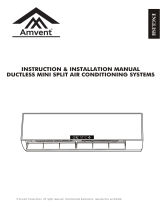
Install the indoor unit level on a strong wall that is not
subject to vibrations.
The inlet and outlet ports should not be obstructed:the
air should be able to blow all over the room.
Do not install the unit near a source of heat , steam,or
flammable gas.
Install the unit near an electric socket or private circuit.
Do not install the unit where it will be exposed to
direct sunlight.
Install the unit where connection between indoor and
outdoor unit is as easy as possible.
Install the unit where it is easy to drain the condensed
water.
Check the machine operation regularly and leave the
necessary spaces as shown in the picture.
Install the indoor unit where the filter can be easily
accessible.
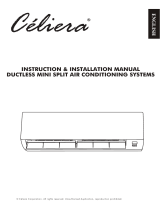
condensed water drain pipe
150
150
150
Sleeve
insulating covering
electrical cable
Mounting plate
Do not install the outdoor unit near sources of heat,
steam or flammable gas.
Do not install the unit in too windy or dusty places.
Do not install the unit where people often pass.Select
a place where the air discharge and operating sound
level will not disturb the neighbours.
Avoid installing the unit where it will be exposed
to direct sunlight ( other wise use a protection , if
necessary, that should not interfere with the air flow).
Leave the spaces as shown in the picture for the air to
circulate freely.
Install the outdoor unit in a safe and solid place.
If the outdoor unit is subject to vibration, place rubber
gaskets onto the feet of the unit..
water drain pipe
300
500
2000
300
minimum space to be left (mm) showing
in the picture
500
Outdoor unit
Indoor unit
Pipe length is
15 meters Max.
aht ssel eb m5 n
dluohs thgieH
Outdoor unit
Indoor unit
Pipe length is
15 meters Max.
be less than 5m
dluohs thgieH
INSTALLATION DIAGRAM
INDOOR UNIT
OUTDOOR UNIT
Only persons and/or companies qualified and experienced in the installation,service and repair of refrigerant
products should be permitted to do so.The purchaser must ensure that the person and/or company who is to
install,service or repair this air conditioner has qualifications and experience in refrigerant products.
SELECTING THE INSTALLATION PLACE
15

1. By using a level, put the mounting plate in a perfect
square position vertically and horizontally.
2. Drill 32 mm deep holes in the wall to fix the
plate;
3. Insert the plastic anchors into the hole;
4. Fix the mounting plate by using the provided tapping
screws
5. Check that the mounting plate is correctly fixed;
50
5mm
Note : Keep the drain pipe down towards the direction
of the wall hole, otherwise leakage may occur.
Before starting installation, decide on the position of the
indoor and outdoor units, taking into account the minim-
um space required around the units
Install the indoor unit in the room to be air conditio-
ning, avoiding to install in corridors or communal
areas.
Install the indoor unit at a height of at least 2.5 m
from the ground.
To install, proceed as follows:
1. Decide where to drill the hole in the wall for the pip-
ing ( if necessary ) according to the position of the
mounting plate;
2. Install a flexible flange through the hole in the wall to
keep the latter intact and clean.
The hole must slope downwards towards the exterior
Note : The shape of the mounting plate may be different
from the one above, but installation method is similar .
Indoors
Outdoors
1. Lift the front panel.
2. Take off the cover as indicated in the piciure ( by
removing a screw or by breaking the hooks).
3. For the electrical connections, see the circuit diagram
on the right part of the unit under the front panel.
4. Connect the cable wires to the screw terminals by
following the numbering ,Use wire size suitable to
the electric power input (see name plate on the unit)
and according to all current national safety code
requirements.
5. The cable connecting the outdoor and indoor units
must be suitable for outdoor use.
6. The plug must be accessible also after the appliance
has been installed so that it can be pulled out if nece-
ssary.
7. An efficient earth connection must be ensured.
8. If the power cable is damaged, it must be replaced by
an authorised Service Centre.
Front panel
Terminal block cover
Wiring diagram
Note:The cable wires has been connected to the main
PCB of indoor unit by manufacturer according to the
model without terminal block
Installation of the mounting plate
Drilling a hole in the wall for the piping
Electrical connections---Indoor unit
INSTALLATION OF THE INDOOR UNIT
16

INSTALLATION OF THE INDOOR UNIT - Continued
3
2
1
The piping can be run in the 3 directions indicated by
numbers in the picture . When the piping is run in
direction 1or3, cut a notch along the groove on the side
of the indoor unit with a cutter.
Run the piping in the direction of the wall hole and bind
the copper pipes , the drain pipe and the power cables
together with the tape with the drain pipe at the bottom,
so that water can flow freely.
Do not remove the cap from the pipe until connecting
it, to avoid dampness or dirt from entering.
If the pipe is bent or pulled too often , it will become
stiff . Do not bend the pipe more than three times at
one point.
When extending the rolled pipe, straighten the pipe by
unwinding it gently as shown in the picture.
1. Remove the indoor unit pipe cap (check that there is
no debris inside).
2. Insert the fare nut and create a flange at the extreme
end of the connection pipe.
3. Tighten the connections by using two wrenches
working in opposite directions
torque wrench
Connecting the pipes
Indoor unit condensed water drainage
The indoor unit condensed water drainage is fundamen-
tal for the success of the installation.
1. Place the drain hose below the piping, taking care not
to create siphons.
2. The drain hose must slant downwards to aid drainage.
3. Do not bend the drain hose or leave it protruding or
twisted and do not put the end of it in water . If an
extension is connected to the drain hose , ensure that
it is lagged when it passes into the indoor unit.
4. If the piping is installed to the right, the pipes, power
cable and drain hose must be lagged and secured onto
the rear of the unit with a pipe connection.
1) Insert the pipe connection into the relative slot.
2) Press to join the pipe connection to the base.
YES
Refrigerant piping connection
Connections to the indoor unit
NO NO
NO
YES
Extending the rolled pipe
Shape the connection pipe
17

INSTALLATION OF THE INDOOR UNIT - Continued
INSTALLATION OF THE OUTDOOR UNIT
18
INSTALLATION OF THE INDOOR UNIT
refrigerant
pipe
refrigerant
pipe
insulation
sleeve
connection
(for heat-pump)
cable 1
connection
cable
Probe
cable(for heat-pump)
Condensed water
drain pipe
Covered by vinyl tape
After having connected the pipe according to the instruc-
tions, install the connection cables. Now install the drain
pipe. After connection,lag the pipe, cables and drain pipe
with the insulating material.
1. Arrange the pipes ,cables and drain hose well.
2. Lag the pipe joints with insulating material , securing
it with vinyl tape.
3. Run the bound pipe , Cables and drain pipe through
the wall hole and mount the indoor unit onto the upper
part of the mounting plate securely.
4. Press and push the lower part of the indoor unit tightly
against the mounting plate
mounting plate
The outdoor unit should be installed on a solid wall
and fastened securely.
The following procedure must be observed before co-
nnecting the pipes and connecting cables : decide
which is the best position on the wall and leave enough
space to be able to carry out maintenance easily.
Fasten the support to the wall using screw anchors
which are particularly suited to the type of wall;
Use a larger quantity of screw anchors than normally
required for the weight they have to bear to aviod
vibration during operation and remain fastened in the
same position for years without the screws becoming
loose.
The unit must be installed following the national
regulations.
drain pipe
The condensed water and the ice formed in the outdoor
unit during heating operation can be drained away thro-
ugh the drain pipe
1. Fasten the drain port in the 25mm hole placed in the
part of the unit as shown in the picture.
2. Connect the drain port and the drain pipe.
Pay attention that water is drained in a suitable place.
Outdoor unit condensed water drainage
(only for heat pump models)
drain port

INSTALLATION OF THE INDOOR UNIT - Continued
19
outdoor unit
remove
the upper
cover
screw
wiring diagram on the
back of the cover
1. Take the cover away.
2. Connect the cable wires to the terminal board using
the same numbering as in the indoor unit.
3. For the electrical connections, see the wiring diagram
on the back of the cover
4. Fasten the cables with a cable-clamp.
5. An efficient earth connection must be ensured.
6. Replace the covers .
Screw the flare nuts to the outdoor unit coupling with
the same tightening procedures described for the indoor
unit.
connection pipes
flare nuts
liquid tap
gas tap
indoor unit
protection caps
liquid valve
gas valve
service port nut
To avoid leakage, pay attention to the following points:
1. Tighten the flare nuts using two wrenches. Pay atten-
tion not to damage the pipes.
2. If the tightening torque is not sufficient , there will
probably be some leakage. With excessive tightening
torque there will also be some leakage, as the flange
could be damaged.
3. The surest system consists in tightening the connecti-
on by using a fix wrench and a torque wrench:in this
case use the table on page 21.
vacuum pump
service port
Air and humidity left inside the refrigerant circuit can
cause compressor malfunction. After having connected
the indoor and outdoor units, bleed the air and humidity
from the refrigerant circuit by using a vacuum pump.
ELECTRICAL CONNECTIONS
CONNECTING THE PIPES
BLEEDING

INSTALLATION OF THE OUTDOOR UNIT - Continued
FINAL STAGES
20
The air and humidity left inside the refrigerant circulat-
ion can cause compressor malfunction. After having co-
nnected the indoor and outdoor units, bleed the air and
humidity from the refrigerant circulation using a va-
cuum pump.
Refrigerant flow direction
2-way valve
(6) Open 1/4 turn
valve cap
(1) Turn
(8) Tighten
(2) Turn
3-way valve
(8) Tighten
(1) Turn
(7) Turn to fully
open the valve
(7) Turn to fully
open the valve
(8) Tighten
Service
port nut
Valve cap
(1) Unscrew and remove the caps from the 2 - way and
3-way valves.
(2) Unscrew and remove the cap from the service port.
(3) Connect the vacuum pump hose to the service port.
(4) Operate the vacuum pump for 10 - 15 minutes until
an absolute vacuum of 10 mm Hg has been reached.
(5) With the vacuum pump still in operation , close the
low - pressure knob on the vacuum pump coupling.
Stop the vacuum pump.
(6) Open the 2 - way valve by 1/4 turn and then close it
after10 seconds. Check all the joints for leaks using
liquid soap or an electronic leak device.
(7) Turn the body of the 2-way and 3-way valves.
Disconnect the vacuum pump hose.
(8) Replace and tighten all the caps on the valves.
3-way valve diagram
connect to indoor unit
open position
spindle
service port cap
Connect to
outdoor unit
Valve core
needle
BLEEDING
Indoor unit
wall
(indoor) (outdoor)
piping
piping
gasket
insulating tape
insulating covering
Clamps
1. Wind insulating covering around the joints of the ind-
oor unit and fix it with insulating tape.
2. Fix the exceeding part of the signal cable to the
piping or to the outdoor unit.
3. Fix the piping to the wall ( after having coated it with
insulating tape) using clamps or insert them into pla-
stic slots.
4. Seal the hole in the wall through which the piping is
passed so that no air or water can fill.
Do the ON/OFF and FAN operate normally?
Does the MODE operate normally?
Do the set point and TIMER function properly?
Does each lamp light normally?
Do the flap for air flow direction operate normally?
Is the condensed water drained regularly?
Is there any abnormal noise or vibration during
operation?
Could the noise , the air flow or the condensed water
drainage disturb the neighbours?
Is there any coolant leakage?
Indoor unit test
Outdoor unit test
Note: the electronic controller allows the compressor to
start only three minutes after voltage has reached
the system.

INFORMATION FOR THE INSTALLER
21
(1) Refer to the data rating label sticked on the outdoor unit.
TIGHTENING TORQUE FOR PROTECTION CAPS AND FLANGE CONNECTION
MODEL capacity (Btu/h)
7k
9k
12k
15/18k
22/24k
28/30k
Liquid pipe diameter
Gas pipe diameter
Lenght of pipe with standard charge
Maximum distance between indoor and outdoor unit
Additional gas charge
Max. diff. in level between indoor and outdoor unit
Type of refrigerant(1)
1/4
(6)
1/4
(6)
1/4
(6)
1/4
(6)
3/8
( 9.52)
3/8
( 9.52)
1/2
( 12)
3/8
( 9.52)
3/8
( 9.52)
5/8
( 15.88)
5/8
( 15.88)
3m 3m
3m 4m
4m 4m
15m 15m 15m 15m 15m 15m
20g/m 20g/m 20g/m 30g/m 30g/m 30g/m
5m 5m 5m 5m 5m 5m
R410A R410A R410A R410A R410A R410A
PIPE
1/4
(6)
3/8
( 9.52)
1/2
( 12)
5/8
( 15.88)
TIGHTENING TORQUE
[N x m]
TIGHTENING TORQUE
[N x m]
CORRESPONDING STRESS
(using a 20 cm wrench)
15 - 20
31 - 35
35 - 45
75 - 80
Service port nut
Protection caps
7 - 9
25 - 30
wrist strength
arm strength
arm strength
arm strength
3/8
( 9.52)
FIXED-SPEED TYPE

INFORMATION FOR THE INSTALLER - CONTINUED
22
OUTDOOR UNIT
INDOOR UNIT
POWER
SUPPLY
OUTDOOR UNIT
INDOOR UNIT
POWER
SUPPLY
WIRING DIAGRAM
FOR 9K-12K-18K-24K COOLING ONLY MODELS
FOR 9K-12K-18K-24K HEAT PUMP MODELS
Note: The cable wires hasbeen connected to the main PCB of indoor unit by manufacturer according to the
model without terminal block, see the wiring diagram on the right part of the unit under the front
panel and the back of the outdoor cover
Please see the pasted diagram instruction on the unit first
110V 220V

INFORMATION FOR THE INSTALLER - CONTINUED
23
CABLE WIRES SPECIFICATION
Type for 220V of fuse used on indoor unit controller for 7K , 9K , 12K 15K , 16K , 18K , 22K , 24K , 30K is
50T with rating 3.15 A , 250V Type for 110V of fuse used on indoor unit controller for 7K , 9K 12k is 50T with
rating 3.15 A , 125V, ; Type of fuse used on inverter outdoor unit controller for 7K , 9K , 12K is 61T with ratin
g
15 A , 250V , for 18K , 22K , 24K is 65TS with rating 25A , 250V.
MODEL capacity (Btu/h)
5k 7k
9k
12k
15/18k
22/24k
28/30k
Power supply cable
Connection supply cable
N
L
E
1
2
3
N
L
2
1.0mm
2
1.0mm
2
1.0mm
2
1.0mm
2
0.75mm
2
0.75mm
2
0.75mm
2
1.0mm
2
1.6mm
2
2.0mm
2
2.0mm
2
2.6mm
2
1.0mm
2
1.0mm
2
(1.5mm)
2
1.0mm
2
1.0mm
2
1.0mm
2
(1.5mm)
2
1.0mm
2
1.0mm
2
1.0mm
2
(1.5mm)
2
1.0mm
2
0.75mm
2
0.75mm
2
0.75mm
2
0.75mm
2
0.75mm
2
0.75mm
2
1.5mm
2
1.5mm
2
1.5mm
2
0.75mm
2
0.75mm
2
0.75mm
2
0.75mm
2
0.75mm
2
0.75mm
2
0.75mm
2
0.75mm
2
0.75mm
2
0.75mm
2
0.75mm
2
0.75mm
2
0.75mm
2
0.75mm
2
0.75mm
2
0.75mm
2
0.75mm
2
0.75mm
sectional area
AWG18 AWG18 AWG14
AWG12
AWG12
2
1.0mm
2
1.0mm
2
1.6mm
2
2.0mm
2
2.0mm
2
2.6mm
AWG18 AWG18 AWG14
AWG12
AWG12
2
1.0mm
2
1.0mm
2
1.6mm
2
2.0mm
2
2.0mm
2
2.6mm
AWG18 AWG18 AWG14
AWG12
AWG12
AWG10
AWG10
AWG10
2
1.6mm
AWG14
2
1.6mm
AWG14
2
1.6mm
AWG14

45 ).
( not higher than 40 ) and neutral soap . Never use
MAINTENANCE
24
Periodic maintenance is essential for keeping your air
conditioner efficient.
Before carrying out any maintenance , disconnect the
power supply by putting the installation on/ off switch to
off .
INDOOR UNIT
ANTIDUST FILTERS
1. Open the front panel following the direction of the
arrow
2. Keeping the front panel raised with one hand, take out
the air filter with the other hand
3. Clean the filter with water ; if the filter is soiled with
oil,it can be washed with warm water (not exceeding
Leave to dry in a cool and dry place.
4. Keeping the front panel raised with one hand , insert
the air filter with the other hand
5. Close
The electrostatic and the deodorant filter (if installed)
cannot be washed or regenerated and must be replaced
with new filters once every 6 months.
CLEANING THE HEAT EXCHANGER
1. Open the front panel of the unit and life it till its
greatest stroke and then unhooking it from the hinges
to make the cleaning easier.
2. Clean the indoor unit using a cloth with the water
aggressive solvents or detergents.
3. If the battery of the outdoor unit is clogged , remove
the leaves and the waste and remove the dust with air
jet or a bit of water.
END OF SEASON MAINTENANCE
1. Disconnect the automatic switch or the plug.
2. Clean and replace the filters
3. On a sunny day let the conditioner work in ventilation for some hours , so that the inside of the unit can
dry completely..
REPLACING THE BATTERIES
When:
How:
N.B: Use only new batteries. Remove the batteries from the remote control when the conditioner is not in
operation
WARNING! Do not throw batteries into common rubbish, they should be disposed of in the special
containers situated in the collection points.
antidust filter
There is no confirmation beep from the indoor unit.
The LCD doesn t activate.
Take off the cover at back.
Place the new batteries respecting the symbols + and - .

COOLING or DEHUMIDIFYING/DRY modes.
TROUBLESHOOTING
25
MALFUNCTION
Strange odour
The appliance does not
operate
Noise of running water
A fine mist comes from
the air outlet
Insufficient airflow, either
hot or cold
The appliance does not
respond to commands
The display is off
Switch off the air condi-
tioner immediately and
cut off the power supply
in the event of:
ERROR SIGNALS ON THE DISPLAY
In case of error, the display on the indoor unit shown the following error codes:
POSSIBLE CAUSES
Power failure/plug pulled out
Damaged indoor/outdoor unit fan motor
Faulty compressor thermomagnetic circuit breaker
Faulty protective device or fuses.
Loose connections or plug pulled out
It sometimes stops operating to protect the appliance.
Voltage higher or lower than the voltage range
Active TIMER-ON function
Damaged electronic control board
Dirty air filter
Back flow of liquid in the refrigerant circulation
This occurs when the air in the room becomes very cold, for example in the
This noise is made by the expansion or contraction of the front panel due
to variations in temperature and does not indicate a problem.
Unsuitable temperature setting.
Obstructed air conditioner intakes and outlets.
Dirty air filter.
Fan speed set at minimum.
Other sources of heat in the room.
No refrigerant.
Remote control is not near enough to indoor unit.
The batteries of remote control nearly has no power.
Obstacles between remote control and signal receiver in indoor unit.
Active LIGHT function
Power failure
Strange noises during operation.
Faulty electronic control board
Faulty fuses or switches.
Spraying water or objects inside the appliance.
Overheated cables or plugs.
Very strong smells coming from the appliance.
The fault of indoor temperature senser
The fault of indoor pipe temperature senser
Malfunction of indoor fan motor.
A strange noise can be
heard
flashes once
RUN lamp
flashes twice
flashes 6 times
Description of the trouble
/