Page is loading ...

OWNERS MANUAL
B2198 – Variable Speed Wood Lathe

2
B2198 VARIABLE SPEED WOOD LATHE
Table of Contents
General Safety Instructions Page3
Specific Safety Instructions Page4
Tool Features Page 5
Electrical Information Page 6
Operating Controls Page 7
Assembly Instructions
Carton Contents Page 8
Leg Set Assembly Page 9
Installing Lathe On Leg Set Page 9
Headlock Handle Page 10
Spurs Page 10
Face Plate Page 11
Extension Bed Page 11
Headstock Page 12
Tailstock Page 13
Articulated Tool Rest Page 13
Operation
Power Switch Page 14
Speed Control Page 14
Maintenance Page 15
Schematic Drawing Page 16
Parts List Page 17
Warranty Page 18
Contact Info Page 19

3
GENERAL SAFETY INSTRUCTIONS
EXTREME CAUTION SHOULD BE USED IN OPERATING ALL POWER TOOLS. KNOW
YOUR POWER TOOL, BE FAMILIAR WITH ITS OPERATION. READ THE OWNER’S
MANUAL AND PRACTICE SAFE USAGE PROCEDURES AT ALL TIMES.
CONNECT your machine ONLY to the matched and specified power
source.
WEAR SAFETY GLASSES, RESPIRATORS, HEARING PROTECTION
and SAFETY SHOES when operating heavy machinery. Always wear
safety glasses.
DO NOT wear loose clothing or jewellery when operating machinery.
A Safe Environment is important. Keep the area free of dust, dirt and
other debris in the immediate vicinity of the machine.
BE ALERT! Do Not Use prescription or other drugs that may affect your
ability or judgement to safely use this machine.
DISCONNECT the power source when changing drill bits, hollow chisels
or making other adjustments or repairs.
NEVER leave an operating tool unattended.
NEVER reach over the table when the tool is in operation.
ALWAYS keep blades, knives or bits sharp and properly aligned.
ALWAYS keep all safety guards in place and ensure their proper function.
ALWAYS use push sticks and featherboards to safely feed your work
through the machine.
ALWAYS make sure that any tools used for adjustments are removed
before operating the machine.
ALWAYS secure your work with the appropriate clamps or vises.
ALWAYS keep bystanders safely away while operating machinery.
THINK SAFETY. WORK SAFELY. Never attempt a procedure if it does
not feel safe or comfortable.

4
B2198 SPECIFIC SAFETY RULES FOR THE WOOD
LATHE
Read and understand the entire owner’s manual before operating the lathe.
Read and understand the warning labels on the lathe.
ALWAYS wear a safety face shield or safety goggles.
Before turning on the B2198, make sure all locks are tightened.
Do not wear gloves, jewellry, neckties or loose clothing.
ALWAYS inspect your workpiece for splits or defects. Do not attempt to turn a defective
workpiece.
ALWAYS use the slowest speed when rough-turning a new workpiece.
ALWAYS make sure that your workpiece runs free and clear of the tool rest and any other
fixed components that may strike the rotating work.
ALWAYS be sure that the tool rest is positioned ABOVE the horizontal center line of the
workpiece.
NEVER allow your turning tools to ‘bite’ into the turning workpiece.
ALWAYS ‘round’ the workpiece before mounting on a faceplate by cutting off as many corners
as possible. Make certain that the faceplate is securely mounted to the headstock.
Check all stock for loose knots and remove them.
Sawdust from some wood species may be toxic. Be aware of this and use the lathe in a well-
ventilated area, use a dust collection system and wear a dust mask.
NEVER reach over a rotating workpiece.

5
B2198 VARIABLE SPEED WOOD LATHE
Features
As part of the growing line of Craftex woodworking equipment, we are proud to offer the
B2198 Variable Speed Wood Lathe. The Craftex name guarantees Craft Excellence. By
following the instructions and procedures laid out in this owner’s manual, you will receive
years of excellent service and satisfaction. The B2198 is a professional tool and like all
power tools, proper care and safety procedures should be adhered to.
Cast-iron bed, headstock, tailstock and tool rest.
Swivel headstock for large, outboard turning.
Articulated tool rest included.
Swing over bed: 12”.
Distance between centers: 33 1/2".
Overall length: 60”.
Tailstock spindle travel: 2 1/4".
Variable speeds: 600 – 2,400 RPM’s.
Motor: 1/2HP, 110 volt, single phase.
Safety (removable key type) power switch included.
Sturdy sheet steel stand included.
Integrated lower accessory shelf included
Morse #2 taper spur headstock included.
Morse #2 taper ‘live’ ball bearing tailstock included.
Threaded headstock faceplate included.
Headstock wrenches (2 – 32mm) included.
Morse taper headstock removal tool included.
Gross weight: 75 kg.

6
B2198 VARIABLE SPEED WOOD LATHE
Electrical Information
In the event of a malfunction or breakdown, grounding provides the path of least
resistance for electrical current to reduce the risk of electrical shock. This lathe is
equipped with an electrical cord that has an equipment grounding conductor wire
and a grounding plug. The plug MUST be plugged into a matching outlet that is
properly installed and grounded in accordance with ALL local codes and
ordinances.
DO NOT MODIFY THE PLUG. If the plug on the 2198 lathe will not fit, have the
proper outlet installed by a qualified electrician.
IMPROPER CONNECTION of the plug-grounding conductor can result in an
electrical shock.
CHECK with a qualified electrician if you are not certain that the 2198 lathe is
properly and safely grounded.
USE ONLY 3-WIRE EXTENSION CORDS that have 3-prong grounding type
plugs.
Repair or replace a damaged electrical cord immediately.
A SEPARATE 15-AMPERE CIRCUIT IS RECOMMENDED FOR STATIONARY
POWER TOOLS SUCH AS THIS.

7
B2198 VARIABLE SPEED WOOD LATHE
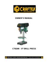
Operating Controls

8
B2198 VARIABLE SPEED WOOD LATHE
Assembly Instructions
Unpacking
Carefully remove the leg set from the carton and set aside.
CAUTION: The B2198 is a heavy machine (75 kg) and must be lifted with
assistance to assemble the lathe to the leg set.
Separate the leg set parts.
Lay out all parts and check them against the parts illustrated below.
Examine all parts carefully.

9
B2198 VARIABLE SPEED WOOD LATHE
Assembly, Continued
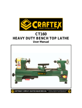
Leg Set Assembly
Attach one front leg and one back leg
(1) to the outside edges of the top
plate (2) using carriage bolts (3),
washers (4) and nuts (5). The top
plate (2) should fit inside the legs (1).
Do not tighten nuts at this time.
Repeat this procedure for the
remaining legs and top plate.
Attach the long stretchers (6) to the
legs using carriage bolts, washers and
nuts.
Attach the short stretchers (7) on the
ends of the legs in the same fashion.
Place the leg stand on a level surface and tighten all nuts securely using a
14mm wrench.
Installing the lathe on the leg set
CAUTION: The lathe is heavy, use assistance for lifting.
Place the lathe unit on the leg set.
Position the headstock (2) assembly
over the top plate and align the holes
of the lathe bed (3) with the holes in
the top plate (4).
Align the tailstock assembly bolt holes
with the top plate holes.
Install the Allen bolts (5) into all of the
mounting holes and through the top
plates.
Install a washer (6) and nut (7) onto
each bolt and tighten securely with a wrench and the supplied Allen keys.
Verify that all nuts and bolts are securely fastened.

10
B2198 VARIABLE SPEED WOOD LATHE
Assembly, Continued
Headlock Handle
Locate and assemble the head locking
handle (1), spring (2) and Allen bolt (3)
as shown.
Thread the head lock assembly into the
head locking clamp and tighten.
Note: Spring loaded handles
The spring-loaded handles on the lathe
are designed to minimize interference with
other lathe parts or the workpiece. To operate
these handles, push the handle in and rotate
clockwise to tighten. Releasing the handle will
disengage the threaded shaft allowing you to reposition the handle so that it is
out of the way.
Spurs
Remove the faceplate (if factory
installed) (1) from the headstock using
the 2 wrenches (2) provided and set
aside.
Insert the headstock spur (3) into the
spindle hole.
Install the tailstock live center into the
tailstock hole.
Removal of spurs
To remove either the headstock spur or
the tailstock live center insert the push
rod (5) through the back access holes of
the headstock and tailstock.
Remove the rod and store it for future
use.

11
B2198 VARIABLE SPEED WOOD LATHE
Assembly, Continued
Faceplate Installation
Remove the headstock spur from the
spindle by using the push-out rod.
Thread the 4” diameter faceplate
onto the spindle and tighten with the
supplied wrenches.
Mount your workpiece to the
faceplate using flat head brass
screws. Be certain that the ends of
the screws will not interfere with your
planned turning.
Extension Bed
The extension bed is attached to the
left of the headstock for outboard
faceplate turning when the use of the
articulated tool rest is required.
If outboard faceplate turning does
not require the use of the tool rest,
do not attach the extension bed until
required.
To attach the extension bed (1) to
the lathe bed, align the bolt holes (2)
with the threaded bed holes (3).
Install a lock washer (4) onto an Allen bolt (5).
Finger tighten and then secure tightly with the Allen key provided.
DO NOT ATTEMPT TO OPERATE YOUR LATHE UNTIL IT IS COMPLETELY
ASSEMBLED AND ADJUSTED ACCORDING TO THE INSTRUCTION
MANUAL.

12
B2198 VARIABLE SPEED WOOD LATHE
Adjustments
Headstock
The headstock has 5 pre-set positions.
0 degrees for all spindle turning
applications, 60, 90 and 120 degrees for
use when making faceplate turnings and
180 degrees when using the extension
bed and the tool rest.
To set the headstock in the desired
position you must first turn the headlock
handle (1) until you have completed at
least one full rotation.
Pull out the headstock release (2).
Rotate the entire headstock in a
clockwise rotation to the desired
position. The headstock will ‘click’ into
one of the pre-set settings.
Tighten the headlock handle (1).

13
B2198 VARIABLE SPEED WOOD LATHE
Operation, Continued
Tailstock
Move the tailstock (1) by loosening
the tailstock lock lever (2) and
sliding the tailstock assembly to the
desired position on the lathe bed.
Securely lock the tailstock into
position by tightening the lock
lever.
The tailstock spindle (3) can
extend up to 2 1/2" from the
tailstock housing. You can move
the tailstock spindle by loosening the spindle lock lever (4) and then
rotating the spindle hand wheel (5).
Be sure that lock levers (4) and (2) are secure before operating the lathe.
The tailstock spindle is hollow and can be accessed from the hand wheel
end. Use the push-out rod to remove the Morse Taper tailstock spindle.
Articulated Tool Rest
The articulated tool rest (1) may be
used with or without the extension
arm (2).
To move the tool rest base (3)
loosen the lock lever (4) and slide
the tool rest base left or right along
the lathe bed or it may be moved
forward or backwards.
When using the tool rest extension
arm you can loosen lock levers (5)
and (6) to make any necessary adjustments.
Be certain to tighten all tool rest locking levers before turning on the lathe.
The articulated tool rest may also be repositioned onto the extension bed
for use on outboard turnings.
IMPORTANT: Make sure that the tool rest is adjusted to be as close to the
workpiece as possible. Rotate the workpiece by hand to check the
clearance before turning the lathe on.

14
B2198 VARIABLE SPEED WOOD LATHE
Operation
Power Switch
Your Craftex B2198 Variable Speed
lathe is equipped with a safety switch to
prevent unauthorised use.
To turn the lathe ‘on’, insert the yellow
switch key into the switch housing.
Move the switch to the ‘on’ position.
To turn the lathe ‘off’, move the switch
to the ‘off’ position.
To lock the switch in the ‘off’ position,
remove the yellow switch key and store it in a safe place.
NEVER leave a running lathe unattended.
Speed Control
The lathe motor must be turned on
before you can use the speed control
lever.
The B2198 speed control lever may be
rotated to any one of ten fixed speeds.
To set the speed, pull back on the
speed control lever (1) and rotate the
lever to the desired speed. Use the
index plate (2) as a reference to select
the desired speed.
Rotating the lever clockwise will
increase the speed while a counter
clockwise rotation decreases the speed.
You must move the speed control
lever to the lowest speed position
before turning the lathe off. Not
complying may prevent the motor
from starting.

15
B2198 VARIABLE SPEED WOOD LATHE
Maintenance
WARNING - FOR YOUR OWN SAFETY, TURN THE LATHE OFF AND
DISCONNECT THE POWER PLUG FROM THE POWER SOURCE BEFORE
PERFORMING ANY MAINTENANCE OR LUBRICATION WORK ON THE
LATHE.
Vacuum and/or blow out any dust accumulation inside the motor housing
on a regular basis.
Apply a coat of paste wax to the lathe bed to help keep it clean and to
facilitate the easy movement of the articulated tool rest and tailstock.
Proper Oiling and maintenance must take place to ensure the quality and
life of the machine. To Maintain this, the use of a pin point oiler would be
helpful. Take the headstock cover off, and oil the point in the diagram.
This should be done periodically.
Periodic lubrication (white grease) of the spring levers and other threaded parts
will make them easier to operate and prevent any possible corrosion.

16
B2198 VARIABLE SPEED WOOD LATHE
Schematic Diagram

17
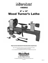
SCHEMATIC DIAGRAM

18
WARRANTY
Craftex warrants every product to be free from defects in materials and agrees to correct such defects where applicable.
This warranty covers two years for parts and 90 days for labour (unless specified otherwise), to the original purchaser
from the date of purchase but does not apply to malfunctions arising directly or indirectly from misuse, abuse, improper
installation or assembly, negligence, accidents, repairs or alterations or lack of maintenance.
Proof of purchase is necessary.
All warranty claims are subject to inspection of such products or part thereof and Craftex reserves the right
to inspect any returned item before a refund or replacement may be issued.
This warranty shall not apply to consumable products such as blades, bits, belts, cutters, chisels, punches etceteras.
Craftex shall in no event be liable for injuries, accidental or otherwise, death to persons or damage to
property or for incidental contingent, special or consequential damages arising from the use of our
products.
RETURNS, REPAIRS AND REPLACEMENTS
To return, repair, or replace a Craftex product, you must visit the appropraite Busy Bee Tools showroom.
Craftex is a brand of equipment that is exclusive to Busy Bee Tools.
For replacement parts directly from Busy Bee Tools, for this machine, please call 1-800-461-BUSY(2879),
and have your credit card and part number handy.
• All returned merchandise will be subject to a minimum charge of 15% for re-stocking and handling
with the following qualifications.
• Returns must be pre-authorized by us in writing.
• We do not accept collect shipments.
• Items returned for warranty purposes must be insured and shipped pre-paid to the nearest warehouse
(see locations on inside back cover of this manual).
• Returns must be accompanied with a copy of your original invoice as proof of purchase. Returns must
be in an un-used condition and shipped in their original packaging a letter explaining your reason for
the return. Incurred shipping and handling charges are not refundable.
• Busy Bee will repair or replace the item at our discretion and subject to our inspection.
• Repaired or replaced items will be returned to you pre-paid by our choice of carriers.
• Busy Bee reserves the right to refuse reimbursement or repairs or replacement if a third party without
our prior authorization has carried out repairs to the item.
• Repairs made by Busy Bee are warranted for 30 days on parts and labour.
• Any unforeseen repair charges will be reported to you for acceptance prior to making the repairs.
• The Busy Bee Parts & Service Departments are fully equipped to do repairs on all products purchased
from us with the exception of some products that require the return to their authorized repair depots. A
Busy Bee representative will provide you with the necessary information to have this done.
• For faster service it is advisable to contact the nearest Busy Bee location for parts availability prior to
bringing your product in for repairs.
CRAFTEX 2 YEAR LIMITED WARRANT
Y

19
Craftex® Tools are Available Exclusively at all Busy
Bee Tools Locations Across Canada
.
BUSY BEE TOOLS - - - SHOWROOMS -Coast to Coast
Head Office
355 Norfinch Drive, North York, Ontario, M3N 1Y7
Tel. - 416-665-8008, Fax – 416-665-8337
Vancouver
30 Braid Street, New Westminister, British Columbia, V3L 3P3
Tel. – 604-517-3922, Fax – 604-517-8272
Mississauga
6325 Dixie Rd. Unit 6 & 7, Mississauga, Ontario, L5T 2E5
Tel. – 905-795-3200, Fax – 905-795-0091
Ottawa
2251 Gladwin Crescent, Ottawa, Ontario, K1B 4K9
Tel. – 613-526-4696, Fax – 613-731-8636
London
1398 Wellington Road, London, Ontario, N5E 1M5
Tel. – 519-659-9868, Fax – 519-659-0771
Dartmouth
133 Ilsley Avenue, Dartmouth, Nova Scotia, B3B 1S9
Tel. – 902-468-8088, Fax – 902-468-8830
Barrie
21 Commerce Park Drive, Barrie, Ontario, L4N 8X1
Tel. – 705-730-0498, Fax – 705-730-0495
Pickering
1064 Salk Road, Pickering, Ontario, L1W 4B5
Tel. – 905-831-9582, Fax – 905-831-4292
Calgary
2611 Hopewell Place, N.E, Unit#109, Calgary, Alberta, T1Y 7K3
Tel – (403) 250-1986, Fax –
(403) 250-7768
We have been serving the Canadian woodworking and metalworking industry for over 28 proud
years. We stand behind all of our machines. If you have any questions, comments, or concerns,
please call or write to our head office or call toll free at 1-800-461-BUSY.
Email us at [email protected] or contact us though our web site at

20
/