Nuaire MRXBOX-ECO Heat Recovery Units Installation guide

Type
Installation guide

Nuaire MRXBOX-ECO Heat Recovery Units are designed to offer improved sound levels and an aesthetically pleasing installation of a Mechanical Ventilation with Heat Recovery unit inside an acoustically lined enclosure. The unit has two independent fans, each with full-speed control for background and boost ventilation rates. It recovers up to 95% of the normally wasted heat. The MVHR unit is suitable for wall mounting on a solid wall only.

Nuaire MRXBOX-ECO Heat Recovery Units are designed to offer improved sound levels and an aesthetically pleasing installation of a Mechanical Ventilation with Heat Recovery unit inside an acoustically lined enclosure. The unit has two independent fans, each with full-speed control for background and boost ventilation rates. It recovers up to 95% of the normally wasted heat. The MVHR unit is suitable for wall mounting on a solid wall only.

1
19. 11. 21. Document Number 672003
Nuaire | Western Industrial Estate | Caerphilly | CF83 1NA | nuaire.co.uk
MRXBOXAB-ECO2B-1ZSW (Standard Hand Unit)
MRXBOXAB-ECO2B-1ZHSW (Opposite Hand Unit)
Mechanical Ventilation Units with Heat Recovery for Wall Mounting
Installation Manual
1.0 SAFETY INFORMATION
The provision of the electrical supply and the connection of the unit to the electrical supply
must be carried out by a qualified electrician in accordance with latest edition of the wiring
regulations.
Isolate from power supply before removing any covers. During installation / maintenance ensure
all covers are fitted before switching on the mains supply.
All-pole disconnection from the mains as shown in the wiring diagram must be incorporated
within the fixed wiring and shall have a minimum contact separation of 3mm in accordance with
latest edition of the wiring regulations.
This unit must be earthed.
Ducting must be securely fixed with screws to the spigot to prevent access to live parts. Duct
runs terminating close to the fan must be adequately protected by suitable guards.
If the supply cord is damaged, it must be replaced by the manufacturer, its service agent or
similarly qualified persons in order to avoid a hazard. The replacement cord must be of the same
technical specification as the original cord or greater.
Precautions must be taken to avoid the back-flow of gases into the room from the open flue of
gas or other fuel-burning appliances.
This appliance should not be used by children or persons with reduced physical, sensory or
mental capabilities or lack of experience and knowledge, unless they have been given supervision
or instruction concerning the safe use of the appliance by a person responsible for their safety.
Children shall not play with the appliance. Cleaning and user maintenance shall not be carried
out by children.
1.1 Hazard Symbols
REFER TO INSTRUCTION MANUAL
Read and understand the installation and maintenance manual before installing,
operating or maintaining this product.
1.2 Important Information
This manual contains important information on the safe and
appropriate assembly, transport, commissioning, operation,
maintenance, disassembly and simple troubleshooting of the product.
While the product has been manufactured according to the accepted
rules of current technology, there is still a danger of personal injury or
damage to equipment if the following general safety instructions and
the warnings contained in these instructions are not complied with.
Read these instructions completely and thoroughly before
working with the product.
Keep these instructions in a location where they are accessible
to all users at all times.
Always include the operating instructions when you pass the
product on to third parties.
1.3 Personal Protective Equipment
The following minimum Personal Protective Equipment (PPE) is
recommended when interacting with Nuaire product:
Protective Steel Toed Shoes - when handling heavy objects.
Full Finger Gloves (Marigold PU800 or equivalent) - when
handling sheet metal components.
Semi Fingerless Gloves (Marigold PU3000 3DO or equivalent)
- when conducting light work on the unit requiring tactile
dexterity.
Safety Glasses - when conducting any cleaning/cutting operation
or exchanging filters.
Reusable Half Mask Respirators - when replacing filters which
have been in contact with normal room or environmental air.
Nuaire would always recommend a site specific risk assessment by a
competent person to determine if any additional PPE is required.
2
19. 11. 21. Document Number 672003
Nuaire | Western Industrial Estate | Caerphilly | CF83 1NA | nuaire.co.uk
MRXBOXAB-ECO2B-1Z(H)SWInstallation Manual
2.0 INTRODUCTION
The ECO2B-1Z wall mounted range of units are designed to offer
improved sound levels and an aesthetically pleasing installation by
housing a Mechanical Ventilation with Heat Recovery unit (MVHR)
and attenuator inside an acoustically lined enclosure.
The MVHR unit is fitted with two independent fans. Each fan has full
speed control for background and boost ventilation rates. To recover
heat from the extract air the heat exchanger block is utilised. The heat
exchanger can recover up to 95% of the normally wasted heat.
If the MVHR unit has integral automatic HX bypass (AB models
only), the bypass damper shall open automatically via a wax actuator
allowing the air to bypass the heat exchanger to deliver fresh filtered air
during the warmer months.
Bypass operation can be disabled via a manual switch in colder months
so the unit recovers heat continually.
Intake air
from outside
Extract air
from house
to house
Supply air
Exhaust air
from house
to outside
Extract air
from house
Intake air
Exhaust air from outside
from house
to outside Supply air
to house
1 Airflow Through Unit (Opposite Hand Unit)
Intake air
from outside
Extract air
from house
to house
Supply air
Exhaust air
from house
to outside
Extract air
from house
Intake air
Exhaust air from outside
from house
to outside Supply air
to house
2 Airflow Through Unit (Standard Hand Unit)
The unit must remain switched on at all times to maintain
ventilation within the dwelling. Turning the unit off will cause long
term damage to the unit and building fabric.
This appliance is not intended for use by persons (including
children) with reduced physical, sensory or mental capabilities,
or lack of experience and knowledge, unless they have been given
supervision or instruction concerning the use of the appliance by a
person for their safety. Children should be supervised so that they
do not play with the appliance.
3.0 MECHANICAL INSTALLATION
Installation must be carried out by competent personnel in accordance
with the appropriate authority and conforming to all statutory
governing regulations. All mains wiring must be in accordance with the
current I.E.E. Regulations, or the appropriate standards. Ensure that the
mains supply (Voltage, Frequency and Phase) complies with the rating
label.
Please allow a minimum of 350mm in front of the enclosure.
The fan must be installed indoors, on a suitable wall away from direct
sources of frost, heat and water spray or moisture generation.
For a vibration-free result the unit must be mounted to a non-
reverberant wall.
3.1 Transportation Fixings
To prevent damage during transportation the product is shipped
with securing fixings, these can be found front and centre of the
enclosure top panel (Figure 3). These must be removed before use,
failure to do so will result in excessive vibration and noise. The
screws removed can be discarded and replaced with rubber caps
provided.
Spigot fixing plate
Transportation fixings
3 Transportation Fixings
3.2 Wall Mounting
The unit is designed for wall mounting on a solid wall only, a gypsum
block/plasterboard wall will not suffice. Examples of suitable
installation are shown overleaf. The wall brackets supplied should be
secured to the wall using suitable fixings (supplied by others) as per
the dimensions given in Figure 4; the head of the chosen fixing should
protrude no more than 8mm from the wall bracket. The enclosure
assembly can then be lifted using suitable equipment and moved into
position so it is sitting directly on the wall brackets (ensuring the rear
panel of the enclosure is not in contact with the wall bracket fixings).
The enclosure can be secured to the wall brackets using the 4x M8
fixings supplied.
No part of enclosure should be in contact with the building structure,
the only components that should be in contact are the wall mounting
brackets.
Care must be taken to ensure the unit is installed true in all 3
dimensions. Failure to do so may result in overflow from the
internal condensation drip tray.
4 Wall Bracket Dimensions
2525 656 crs
9.1 dia.
30
94
94
33
3
19. 11. 21. Document Number 672003
Nuaire | Western Industrial Estate | Caerphilly | CF83 1NA | nuaire.co.uk
MRXBOXAB-ECO2B-1Z(H)SWInstallation Manual
3.3 Condensate Drain
The MVHR unit inside the enclosure is fitted with a straight coupling to
allow 21.5mm overflow pipe (not supplied) to be attached using solvent
cement, the pipe should be passed through the flexible adhesive backed
cover plate before the solvent cement is applied.
The pipe can then be inserted into the coupling of the MVHR unit and
the cover plate slid along the length to bond against the base panel of
the enclosure preventing noise breakout (Figure 7).
1. The condensate must be discharged under a water level in a U-trap
drainpipe or an alternative drain method which acts as an airlock.
2. This condensate discharge connection is suitable for 21.5mm dia.
overflow pipe. Solvent cement should be used to make the joint.
3. If using a U-trap please ensure the U-trap has been filled to a
suitable level of water to avoid any air locks.
4. If the condensation pipe is fitted in an unheated space the pipe
should be in insulated to prevent freezing.
Nuaire recommend MVHR-DRAIN be used as the primary
condensate take-off (Figures 9 and 10).
7 Wall Bracket Dimensions
Solvent cement to be applied
Flexible adhesive backed
cover plate
Overflow pipe
Min 5o Drop
8 Condensate Drain - Wet Connection: Unit Pipe Connection To
Typical “U” Trap Drainpipe Example
Collar
9 Condensate Drain - MVHR-DRAIN: Condensate Drain,
Uninsulated Drain Pipe With Min 5° Fall Running To SVP.
3.2.1 Solid Wall Mounting (Recommended)
The MVHR unit fixed to a solid wall construction using the
mounting bracket provided.
Ducting in the
ceiling void.
Side view of unit
mounted on the
block wall in a
cupboard using
MVHR-DRAIN
the wall brackets.
Condensate drain,
uninsulated drain
pipe with min 5o fall
running to SVP.
Valve in ceiling.
Unit weight
= 58kG
5 Cupboard Mounted Unit Fixed to Block Work Wall Example
3.2.2 Stud Partition Wall Mounting (Alternative)
If it is not practical to use a solid wall, the unit should be fixed to a
stud partition with a 25mm minimum thickness MDF panel solidly
fixed behind the plasterboard.
If fixing to a stud wall the MDF panel should extend, width wise, over
a minimum of 3 vertical studs with centres of no more than 400mm.
A vertical stud should be located to correspond with the position each
mounting bracket is to be fixed to provide additional support.
Add additional vertical supports if necessary. Height wise, the MDF
panel should extend from floor to ceiling.
Fix the mounting bracket to the wall (Figure 4) and use the wall
mounted bracket to mount the unit on (as shown in Figure 6).
6 Cupboard Mounted Unit Fixed to Stud Partition Wall Reinforced
With MDF Panel Example
Ducting in the
ceiling void.
Side view of unit
mounted in a
with the 25mm
cupboard fixed to
a stud partition
MDF fixed behind
the plasterboard
using the wall
MVHR-DRAIN
brackets.
Condensate drain,
uninsulated drain
pipe with min 5o fall
running to SVP.
Valve in ceiling.
Unit weight
= 58kG
4
19. 11. 21. Document Number 672003
Nuaire | Western Industrial Estate | Caerphilly | CF83 1NA | nuaire.co.uk
MRXBOXAB-ECO2B-1Z(H)SWInstallation Manual
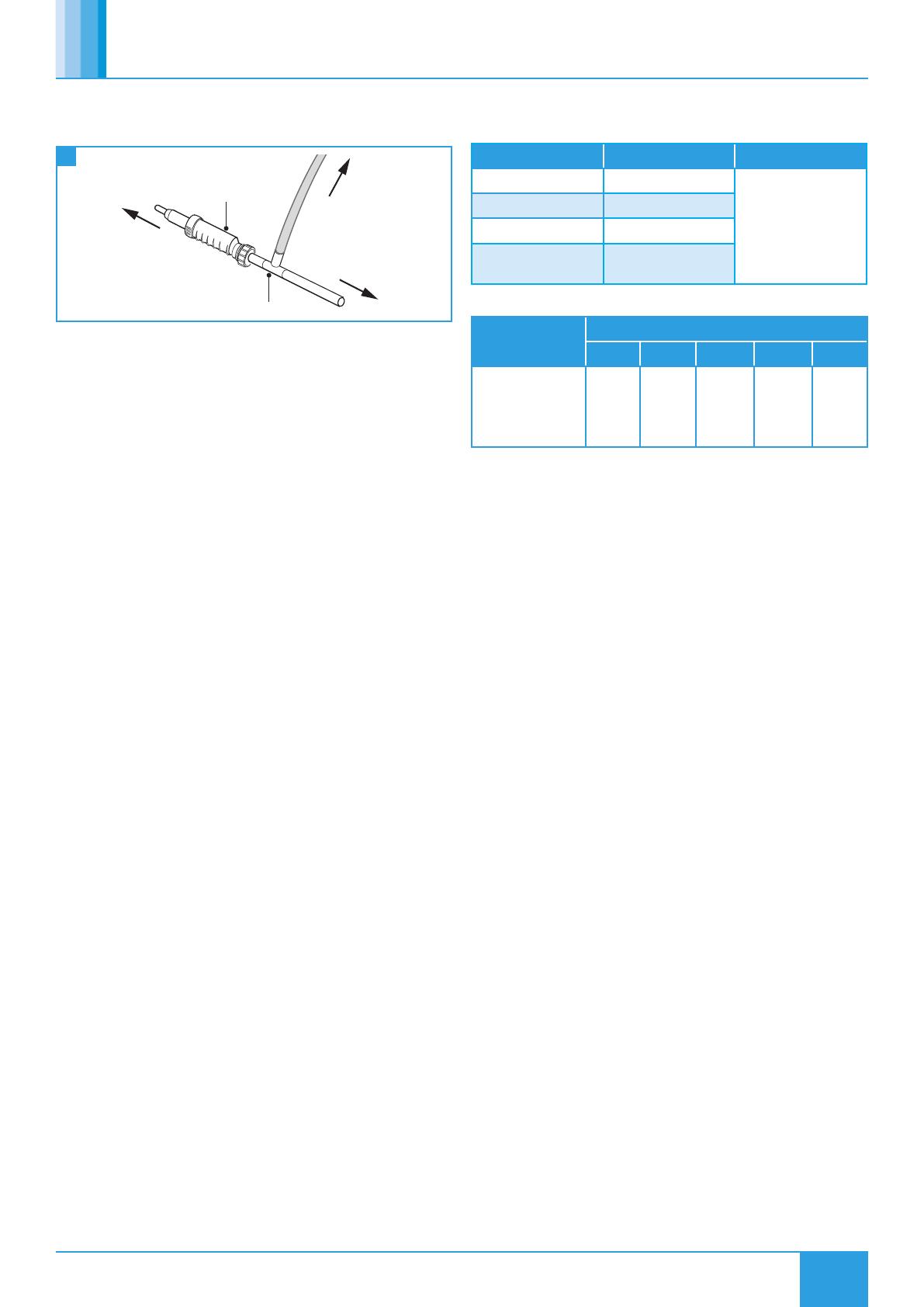
When using a “T” Piece to connect the CONTRAP drainage and
the MVHR drain pipework the MVHR drain must always be fitted
before the “T” Piece.
10 Condensate Drain "T" Piece Installation
To SVP
“T” piece
MVHR Drain
To unit
To CONTRAP
3.4 Extract & Supply Areas
The unit is designed to extract air from all wet rooms e.g. bathroom,
kitchen, en-suite, utility room (with sink). WC’s do not need to be
ventilated if openable windows are fitted.
Supply air should be to all habitable rooms e.g. bedrooms and lounge.
Extract / input grilles should be adjustable valve types (not supplied).
External grilles are to have a minimum free area of 12,250 mm2.
3.5 Ducting
Before commencing ducting installation reference should be made
to building regulations document “Domestic ventilation compliance
guide”. This document supports ADF2010 and details installation,
testing and commissioning of all ventilation systems.
If the enclosure is to be used in conjunction with an ancillary
distribution box (MRXBOX-DB2) refer to additional assembly
instructions supplied with the MRXBOX-DB2 as requirements will
differ.
Otherwise fit 4x 125mm diameter plastic spigots with the self-tapping
screws supplied to the spigot fixings plates found on the top panel of
the enclosure, a bead of silicone should be applied to the groove of
spigot fixing plate to prevent leakage (Figure 3).
It is recommended that rigid ducting be used at all times. Flexible
ducting has a very high resistance and it is impossible to calculate how
much resistance will be on a system if used.
If used the flexible ducting must be kept to a minimum and should
always be pulled taut. A maximum of 300mm should be used on each
leg.
To prevent condensation on the outside of the outside air inlet duct and
the air outlet duct from the unit, these ducts should be insulated.
Ducting must be installed in such a way that resistance to airflow is
minimised. Bends should be kept to a minimum.
A minimum distance of 300mm between the appliance and any bends
in ductwork is recommended.
Ideally 125mm diameter or 220 x 90mm rectangular ducting should
be used (Refer to dwelling design drawing, Figures 12 & 13 for further
information).
Ducting joints must be sealed with silicone type sealant and shall be
adequately and reliably fixed to the appliance.
Any air intake terminal MUST be installed in accordance with the
appropriate regulation.
As a guide, the BS5440 series of British Standards deals with this
issue and currently states that an air intake must be at a minimum
distance of 300mm from a gas boiler balanced flue.
Installers are advised to be aware of the requirements of this
standard when installing ‘through the wall’ supply air ducting.
3.6 Ventilation Flow Rates
3.6.1 ADF 2010 - Extract Ventilation Rates
Room Min high rate Min low rate
Kitchen 13 l/s Total extract rate
should be at least
the whole dwelling
ventilation rate given
in table 2.
Utility Room 8 l/s
Bathroom 8 l/s
Sanitary
Accommodation 6 l/s
3.6.2 Whole Dwelling Ventilation Rates
Number of bedrooms in dwelling
1 2 3 4 5
Whole dwelling
ventilation rate
(l/s)
1,2
13 17 21 25 29
1. In addition, the minimum ventilation rate should be no less than
0.3 l/s per m2 of internal floor area. (This includes all floors, e.g.
for a two-story building add the ground and first floor areas).
2. This is based on two occupants in the main bedroom and a single
occupant in all other bedrooms. This should be used as the default
value. If a greater level of occupancy is expected add 4 l/s per
occupant.
3.7 ADF 2010 Ventilation Calculations Design Of MVHR
Systems
The MVHR system has been sized for the winter period. Additional
ventilation may be required during the warmer months and it has
been assumed that the provisions for purge ventilation (e.g. openable
windows) could be used.
Step 1: For any design air permeability, determine the whole dwelling
ventilation supply rate from Table 2.
As an alternative where the design air permeability is intended to be
more than (>) 5m3/(h.m2) 50 Pa, allow for infiltration for all dwelling
types by subtracting from the whole dwelling ventilation supply rate
from Table 2; 0.04 x gross internal volume of the dwelling heated
space (m3).
Step 2: Calculate the whole dwelling extract ventilation rate by
summing the individual room rates for ‘minimum high rate’ from Table
1.
(For sanitary accommodation only, as an alternative, the purge
ventilation provisions given in ADF 2010 can be used where security is
not an issue. In this case ‘minimum high extract rate’ for the sanitary
accommodation should be omitted from the step 2 calculation).
Step 3: The required airflow rates are as follows:
The maximum whole dwelling extract ventilation rate (e.g. boost)
should be at least the greater of step 1 and step 2. Note that the
maximum individual room extract rate should be at least those
given in table 1.
The minimum air supply rate should be at least the whole building
ventilation rate found in step 1.
For Scotland refer to BRE Digest 398.
For further information refer to “Domestic Ventilation Compliance
Guide” www.planningportal.gov.uk/buildingregulations/approved
documents/partl/compliance
5
19. 11. 21. Document Number 672003
Nuaire | Western Industrial Estate | Caerphilly | CF83 1NA | nuaire.co.uk
MRXBOXAB-ECO2B-1Z(H)SWInstallation Manual
3.8 Pre Commissioning MRXBOX MVHR Units
MRXBOX units are designed to ventilate the whole dwelling and must
not be used during site construction or the clean-up period. Cement
and plaster dust can be abrasive and can affect fan performance
and reliability. Please ensure that the filters are checked prior to
commissioning to ensure there is no build-up of dust or debris.
While the property is drying out, very high moisture levels are likely
to occur. Therefore it is advisable that if the installation and building
works are complete the unit is left running. If the building works are
not complete please close the air valves or cover up the air valves to
prevent condensation forming in the ductwork and the MRXBOX95
unit due to natural migration of warm air.
3.9 Dimensions (mm)
1053
706 448
55
172 CRS 144
417 CRS
==
142
UNI T WEI GHT = 58Kg
CO
N
DE
ondensate dr
N
SATE DRAIN
C
ain connection
O
NN
ECTIO
N
142
Ø125.0
(O
PPO
SIT
opposite hand conf
E HAN
D CO
N
igur
FIG
U
ation)
RATIO
N)
Condensate drain
connection
(standard
configuration)
Condensate drain
connection
on centre line
of unit
Condensate drain connection
(opposite hand configuration)
if ancillary distribution box MRXBOX-DB2 is to be used refer to documentation
supplied with MRXBOX-DB2 for additional infomation as requirements will differ.
11 Dimensions
6
19. 11. 21. Document Number 672003
Nuaire | Western Industrial Estate | Caerphilly | CF83 1NA | nuaire.co.uk
MRXBOXAB-ECO2B-1Z(H)SWInstallation Manual
3.10 Ducting Arrangements - Standard Configuration Unit
3.10.1 Circular Ducting
Air supply
to lounge
in ceilings.
via Air Valve
Extract air
from
kitchen/
bathroom
in ceilings.
via Air Valve
Exhaust air from
kitchen/bathroom to
outside via louvre grille.
Minimum distance as specified
in building regulations.
Intake air
from outside
via louvre grille.
All duct between MVHR
unit and atmosphere to
be insulated*.
Exhaust air from
kitchen/bathroom to
outside via air brick.
Minimum distance as specified
in building regulations.
Intake air
from outside
via air brick.
All duct between MVHR
unit and atmosphere to
be insulated*.
*Insulated
supply duct.
*Insulated
supply duct.
Air supply
to lounge
in ceilings.
Extract
via Air Valve air from
kitchen/
bathroom
in ceilings.
via Air Valve
Air supply
to bedrooms
in ceilings.
via Air Valve
Top of ceiling void.
Air supply to
bedrooms
in ceilings.
via Air Valve
*Insulated
extract duct.
*Insulated
extract duct.
MVHR unit.
Nuaire
MVHR-DRAIN
Condensate drain, uninsulated
drain pipe with min 5 o fall running to SVP.
MVHR unit.
Nuaire
MVHR-DRAIN
Condensate drain, uninsulated
drain pipe with min 5 o fall running to SVP.
12 Typical Ducted Arrangement For A Wall Mounted Unit Using Circular Ducting
3.10.2 Rectangular Ducting
Air supply
to lounge
in ceilings.
via Air Valve
Extract air
from
kitchen/
bathroom
in ceilings.
via Air Valve
Exhaust air from
kitchen/bathroom to
outside via louvre grille.
Minimum distance as specified
in building regulations.
Intake air
from outside
via louvre grille.
All duct between MVHR
unit and atmosphere to
be insulated*.
Exhaust air from
kitchen/bathroom to
outside via air brick.
Minimum distance as specified
in building regulations.
Intake air
from outside
via air brick.
All duct between MVHR
unit and atmosphere to
be insulated*.
*Insulated
supply duct.
*Insulated
supply duct.
Air supply
to lounge
in ceilings.
Extract
via Air Valve air from
kitchen/
bathroom
in ceilings.
via Air Valve
Air supply
to bedrooms
in ceilings.
via Air Valve
Top of ceiling void.
Air supply to
bedrooms
in ceilings.
via Air Valve
*Insulated
extract duct.
*Insulated
extract duct.
MVHR unit.
Nuaire
MVHR-DRAIN
Condensate drain, uninsulated
drain pipe with min 5 o fall running to SVP.
MVHR unit.
Nuaire
MVHR-DRAIN
Condensate drain, uninsulated
drain pipe with min 5 o fall running to SVP.
13 Typical Ducted Arrangement For A Wall Mounted Unit Using Circular Ducting
New
ALSO FROM NUAIRE -
range of thermal ducting,
an all-in-one insulated ducting system
(see installation document 671780)
7
19. 11. 21. Document Number 672003
Nuaire | Western Industrial Estate | Caerphilly | CF83 1NA | nuaire.co.uk
MRXBOXAB-ECO2B-1Z(H)SWInstallation Manual
4.0 ELECTRICAL INSTALLATION
For good EMC engineering practice, any sensor cables or switched
live cables should not be placed within 50mm of other cables or on
the same metal cable tray as other cables.
The electrical connection of the unit must be carried out by a
qualified electrician.
The unit is supplied with a flexible cord for connection to the mains
supply.
4.1 Electrical Information
Electrical details:
Voltage: 240V 1ph 50Hz
Consumption: 1.2 Amp
This unit must be earthed.
The cable from the mains power supply should be connected to a
fixed wiring installation, via a fused isolator, in accordance with
current IEE wiring regulations.
Wiring is for reference purposes only as the connections in Figure
14 are factory fitted. The unit is pre-wired with a 2 metre fly lead.
EXTRA
EXTRA
CT F
CT F
AN
Supply Extract Supply Extract Supply Extract
SPEED 1 SPEED 2 SPEED 3
14 PCB Details
4.2 Wiring Diagrams
4.2.1 Unit Serving Kitchen & Bathroom
Optional Controls - For further information regarding optional controls, contact Nuaire on 02920 858 400.
Disconnection from the
supply mains must be
incorporated within the
fixed wiring in accordance
with the wiring
regulations and shall
have a minimum contact
separation of 3mm.
3A Fuse
(BS 1362)
MAINS
230V
50Hz
Light
Room
Light
Switch
(Double
Pole)
N
L
3 Pole
Isolator
Kitchen Switch
Blue
Brown
Black
Optional 3 Speed Switch
Supply Cord
From Unit
Grey
Green / Yellow
15 Wiring Diagram - Kitchen & Bathroom
4.2.2 Unit Serving Kitchen & 2 Bathrooms
Disconnection from the
supply mains must be
incorporated within the
fixed wiring in accordance
with the wiring
regulations and shall
have a minimum contact
separation of 3mm.
3A Fuse
(BS 1362)
MAINS
230V
50Hz
Room
Lights
Light
Switches
(Double
Pole)
N
L
3 Pole
Isolator
Kitchen Switch
Blue
Green / Yellow
Brown
Black
Supply Cord
From Unit
Optional 3 Speed Switch
Grey
16 Wiring Diagram - Kitchen & Bathroom
4.2.3 Summer / Winter Switch
17 Wiring Diagram - Summer / Winter Switch
Black
2 core cable
from unit
Red
Volt free Summer / Winter Switch (supplied with unit)
Polarity is inconsequential
Warning! - Do not connect to mains!
8
19. 11. 21. Document Number 672003
Nuaire | Western Industrial Estate | Caerphilly | CF83 1NA | nuaire.co.uk
MRXBOXAB-ECO2B-1Z(H)SWInstallation Manual
5.0 COMMISSIONING
The filters fitted inside the unit are protected with a plastic film.
Prior to commissioning remove the covers (Figure 20, take off the
film and replace.
For the required air flow rates please refer to the design
specification for the property, follow Section 3.7, or refer to
building regulations ADF 2010.
The unit is supplied with independent control for both normal and
boost airflows (Figure 18).
Correct commissioning is essential to ensure the ventilation air
flow rates are met. It also ensures the unit is not over ventilating
and causing excessive power consumption.
Commissioning should be carried out in accordance with building
regulations document “Domestic ventilation compliance guide”.
www.planningportal.gov.uk/building regulations/approved
documents/partf/associated
A calibrated moving vane anemometer and hood will be required
to carry out commissioning.
Adjustment valves should be locked in place to prevent further
adjustment.
Once commissioned the home owner / tenant should be informed
that the unit should not be adjusted as it will have a detrimental
effect on the indoor air quality and could result in condensation
and mould growth. The clear panel covering the control has
an adhesive panel which should be exposed and sealed post
commissioning to prevent tampering.
Speed 1 is limited to never exceed speed 2, when commissioning
speed 2 should always be set first.
18 Front Panel Unit Control Detail
Humidity adjustment situated
behind front panel, panel must
be removed for access.
This should only be carried
out by a qualified person.
+
-
Post commissioning remove
adhesive backing and seal
Power Fan
Failure
+
-
Ventilation Controls
-
+
+
-
+
-
Speed 1
-
+
Speed 2 Speed 3
Supply Extract Supply Extract Supply Extract
6.0 CONTROLS
6.1 Humidity Adjustment
This product contains an internal humidity sensor fitted into the air-
flow extracting from the wet rooms. When the unit senses that the
humidity exceeds the set point the unit will boost to that set by the
commissioned boost speed. The set point can be found behind the front
of the unit (Figure 18) and is at its least sensitive when turned fully
clockwise. Note that the sensor is measuring humidity from all the wet
rooms at the same time and should not be relied on to solely boost
the unit. Additional switch should be used local to the wet rooms (see
wiring diagrams).
Adjustment only to be carried out by qualified person, isolate
power before removing cover.
6.2 Status Indication
The status of the unit is indicated by a series of LED’s on the front cover.
The variants are listed below.
The display on the unit control panel will not indicate when a
higher speed setting has been triggered by an external source.
19 LED Indicators
HX Bypass
(AB units only)
Speed 1
Speed 2
Speed 3
Supply Fan Fault
Extract Fan Fault
Frost Protection
Filter Change
6.3 Integral Automatic HX Bypass
Intake and extract temperatures are monitored at the point the
airflows enter the unit, if the range falls within the set parameters the
bypass damper is opened automatically to target an indoor comfort
temperature all year round.
The extract temperature is an average from all wet rooms. If this
exceeds 25°C the unit may go into bypass depending on outside
temperatures.
6.4 Summer / Winter Switch
When the switch position is set to Summer the integral automatic
summer bypass is fully operational, in the alternative Winter position
the HX bypass is disabled to ensure the unit is constantly in heat
recovery mode.
6.5 Speed 3 Operation (SW Units Only)
Speed 3 will be non-operational if the intake temperature is greater
than the extract temperature.
6.6 Frost Protection
In the event of the intake air temperature at the unit dropping below
the predetermined set point (-5°C as standard) the supply fan will
reduce to minimum speed, once the temperature rises above the set
point the fan will return to its commissioned speed.
Please note this mode will only activate after ten days of continuous
9
19. 11. 21. Document Number 672003
Nuaire | Western Industrial Estate | Caerphilly | CF83 1NA | nuaire.co.uk
MRXBOXAB-ECO2B-1Z(H)SWInstallation Manual
run time. If commissioning of the unit is outside of this time frame
please notify the after sales department prior to site visit.
7.0 MAINTENANCE
It is important that maintenance checks are recorded and that the
schedule is always adhered to, in all cases, the previous report should
be referred to.
Isolation - Before commencing work make sure that the unit,
switched live and control are electrically isolated from the mains
supply and switched live supply.
7.1 Routine Maintenance
Nuaire recommend that filters are inspected every 6 months and
replaced every 12 months. A flashing LED (Section 6.2) will indicate that
a filter change is required. This indication repeats every 12 months and
will turn off automatically after 5 Days.
Remove the filter covers on the front panel of the unit by gripping the
two circular tabs either end of the filter covers and pulling away from
the unit. The filter can now be extracted by pulling the removal loop on
the front edge of the filter. Once the filters have been inspected return
or replace them as necessary.
Inspect the heat exchanger every 5 years. Generally check for damage
and security of components. Refit cover.
20 Filter Removal
Filter
Filter cover
Outer enclosure cover
MVHR unit cover
Heat exchanger
8.0 WARRANTY
The 5 year warranty starts from the day of delivery and includes parts
and labour for the first year. The remaining period covers replacement
parts only.
This warranty is void if the equipment is modified without
authorisation, is incorrectly applied, misused, disassembled, or not
installed, commissioned and maintained in accordance with the details
contained in this manual and general good practice.
The product warranty applies to the UK mainland and in accordance
with Clause 14 of our Conditions of Sale. Customers purchasing from
outside of the UK should contact Nuaire International Sales office for
further details.
Failure to maintain the unit as recommended will invalidate the
warranty.
9.0 END-OF-LIFE AND RECYCLING
Where possible Nuaire use components which can be largely recycled
when the product reaches its end-of-life:
Fans, motors, controls, actuators, cabling and other electrical
components can be segregated into WEEE recycling streams.
Sheet metal parts, aluminium extrusion, heating/cooling coils and
other metallic items can be segregated and fully recycled.
EPP, plastic ducting, nylon corner pieces, plastic heat exchangers,
packaging material and other plastic components can be
segregated into mixed plastic and widely recycled.
Cardboard packaging, wood, used filters and other paper
components can be largely recycled or fully processed in energy
from waste centres.
Remaining Items can be further segregated and processed in
accordance with the zero waste hierarchy. Please call After Sales
Support for further information on items not listed above.
Ensure that Nuaire product is made safe from any electrical / water
/ refrigerant supplies before dismantling commences. This work
should only be undertaken by a qualified person in accordance with
local authority regulations and guidelines, taking into account all
site based risks.
10.0 AFTER SALES AND REPLACEMENT PARTS
For technical assistance or further product information, including spare
parts and replacement components, please contact the After Sales
Department.
If ordering spares please quote the serial number of the unit together
with the part number, if the part number is not known please give a full
description of the part required. The serial number will be found on the
identification plate attached to the unit casing.
The supply cable must be replaced by an electrically competent
person.
Telephone 02920 858 400
aftersales@nuaire.co.uk
Technical or commercial considerations may, from time to time,
make it necessary to alter the design, performance and dimensions
of equipment and the right is reserved to make such changes without
prior notice.
10
19. 11. 21. Document Number 672003
Nuaire | Western Industrial Estate | Caerphilly | CF83 1NA | nuaire.co.uk
MRXBOXAB-ECO2B-1Z(H)SWInstallation Manual
NOTES
11
19. 11. 21. Document Number 672003
Nuaire | Western Industrial Estate | Caerphilly | CF83 1NA | nuaire.co.uk
MRXBOXAB-ECO2B-1Z(H)SWInstallation Manual
NOTES
12
19. 11. 21. Document Number 672003
Nuaire | Western Industrial Estate | Caerphilly | CF83 1NA | nuaire.co.uk
MRXBOXAB-ECO2B-1Z(H)SWInstallation Manual
NOTES
  • Page 1 1
  • Page 2 2
  • Page 3 3
  • Page 4 4
  • Page 5 5
  • Page 6 6
  • Page 7 7
  • Page 8 8
  • Page 9 9
  • Page 10 10
  • Page 11 11
  • Page 12 12

Nuaire MRXBOX-ECO Heat Recovery Units Installation guide

Type
Installation guide

Nuaire MRXBOX-ECO Heat Recovery Units are designed to offer improved sound levels and an aesthetically pleasing installation of a Mechanical Ventilation with Heat Recovery unit inside an acoustically lined enclosure. The unit has two independent fans, each with full-speed control for background and boost ventilation rates. It recovers up to 95% of the normally wasted heat. The MVHR unit is suitable for wall mounting on a solid wall only.

Ask a question and I''ll find the answer in the document

Finding information in a document is now easier with AI