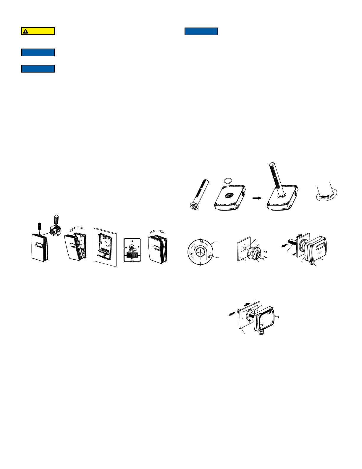
Dwyer PMI Series User manual

Type
User manual

Dwyer PMI Series particulate matter transmitters are designed to measure indoor air quality by detecting particles as small as 0.3 μm in offices, healthcare facilities, hotels, restaurants, and other indoor environments. They use laser scattering technology to accurately measure PM2.5 and PM10 levels, and can be used as stand-alone controllers with their built-in relay, alarm, and control modes. With a long service life of up to 10 years in auto mode and minimal downtime due to overvoltage protection, these transmitters are ideal for long-term air quality monitoring.

Dwyer PMI Series particulate matter transmitters are designed to measure indoor air quality by detecting particles as small as 0.3 μm in offices, healthcare facilities, hotels, restaurants, and other indoor environments. They use laser scattering technology to accurately measure PM2.5 and PM10 levels, and can be used as stand-alone controllers with their built-in relay, alarm, and control modes. With a long service life of up to 10 years in auto mode and minimal downtime due to overvoltage protection, these transmitters are ideal for long-term air quality monitoring.

Series PMI Particulate Matter Transmitter
Specications - Installation and Operating Instructions
Bulletin AQ-PM
DWYER INSTRUMENTS, INC.
P.O. BOX 373 • MICHIGAN CITY, INDIANA 46360, U.S.A.
Phone: 219-879-8000
Fax: 219-872-9057
www.dwyer-inst.com
The Series PMI Particulate Matter Transmitter is designed to measure indoor air
quality by detecting particulate matter in an ofce environment or HVAC duct. Using
laser scattering technology, the Series PMI can measure particles as small as 0.3
μm, making it an essential component of any indoor air quality monitoring system.
The optional relay combined with the settable alarm and control parameters allow the
Series PMI to be a stand-alone controller.
BENEFITS/FEATURES
Maintains healthy air supply with long term stability and accuracy
Particulate matter application independent as duct and wall mount units are
available
Low maintenance with 10 years of service life in auto mode
Minimal downtime with overvoltage protection
Easy setup with optional integral display and buttons
Saves time using removable terminal block on duct mount model
Single unit controller with alarm, control modes, and optional relay
APPLICATIONS
Educational institutions
Healthcare facilities
Corporate ofces
Hotels/restaurants
Air puriers
Wall mount
Duct mount
Wall mount with LCD
Duct mount with LCD
Wall mount
Duct mount
SPECIFICATIONS
Sensor: Laser scattering.
Range: PMI-2.5: 0-500 μg/m3, particle size 0.3-2.5 μm; PMI-10: 0-600 μg/m3,
particle size 0.3-10 μm.
Accuracy: ±10 μg/m3 @ 0-100 μg/m3; ±10% reading @ 100-600 μg/m³ @ 25°C,
50% RH.
Resolution: 1 μg/m3.
Response Time: <10 s, continuous service mode.
Temperature Limits: Operating: 32 to 122°F (0 to 50°C); Storage: -22 to 158°F
(-30 to 70°C).
Humidity Limits: 0-95% RH (non-condensing).
Power Requirements: 16-28 VAC/6-35 VDC.
Load Resistance: Current output: ≤500 Ω; Voltage output: ≥2 kΩ.
Output: Current: 4-20 mA; Voltage: 0-10 VDC; Relay: SPST 3A, 30 VDC/250 VAC;
RS-485/Modbus® (RTU).
Service Life: MTBF more than 3 years in continuous service mode, service life up
to 8-10 years in auto (intermittent) service mode.
Display: Optional 4-digit LCD.
Housing Materials: Wall mount: Polycarbonate (UL 94 V-0); Duct mount: ABS and
polycarbonate (UL 94 V-0).
Enclosure Rating: Wall mount: IP30; Duct mount: IP65 (housing), IP30 (probe).
Weight: Wall mount: 7.05 oz (200 g); Duct mount: 9.5 oz (270 g).
Compliance: CE, UKCA.
3-17/64
[83]
4-17/32
[115]
3-17/64
[83]
4-17/32
[115]
63/64
[25]
1-13/64 [30.6]
3-11/64
[80.5]
2-23/64
[60] 1-3/16
[30]
3-5/16
[84]
Ø5/32 [Ø4]
43/64 [17]
4-59/64
[125]
1-17/64 [32]
3-13/16
[97]
4-21/64
[110]
2-61/64
[75]
2-61/64
[75]
4-21/64
[110]
Duct Mounting
To duct mount the transmitter:
First, the probe must be attached to the back of the enclosure as shown in Figure
2A by inserting the provided black seal ring in the groove located on the back of the
housing. Next, align the probe latches with the cutouts on the back of the housing
and gently turn it according to the direction indicated on the probe until it snaps
into place.
Mount using one of the following ways, ensuring that all sampling holes on the
probe are inserted into the duct and that the direction indicated on the front cover
is the same as the direction of the air ow inside of the duct.
To install via the ange as shown in Figure 2B, drill a Ø19 mm hole in the duct,
install the seal ring and the ange onto the duct using three of the four provided
shorter screws. Then, insert the probe into the duct. Use the last provided short
screw to lock the whole enclosure onto the ange.
◦To install the enclosure directly on the duct as shown in Figure 2C, drill a Ø19
mm hole on the duct, insert the probe with the seal ring, and screw the enclosure
on the duct directly using the two longer screws provided.
Remove the four screws from the front cover and lift to access the wiring. Wire
according to the wiring diagram inside the front cover. Once completed, replace the
front cover.
INSTALLATION
This product is suitable for common environment measurement. If it is installed in an
environment exceeding the acceptable measurement range for a long period of time,
it may lead to the decrease of the measurement accuracy. In any environment with
high humidity, high temperature, smoke, etc., the performance of the sensor may also
be decreased due to excessive contaminants, such as dust and oil mist, etc.
Choose a location with good ventilation and without strong light or vibration. Direct light
or vibration can affect the accuracy of the sensor.
The unit should be powered OFF during installing and wiring. When using 24 VAC,
it is strongly recommended to power the unit with an independent transformer. If
sharing a 24 VAC transformer with other equipment, such as controllers, transmitters
or actuators, please make sure the terminals 24 V and GND are connected correctly
to avoid equipment damage that is not covered under warranty.
Surface Mounting:
The wall mount models should be installed vertically on a at surface. The installation
site should be far away from any heater, cooler, fan, humidier, dehumidier, and other
heat/cool/humidity sources. To mount the transmitter:
Use a athead screwdriver and insert it into the snap at the upper side of the
housing. Push down gently and then open the front cover.
Feed the cable into the housing before installing the base on the wall according to
the diagram inside the front cover.
Finish electrical connection according to the wiring diagram in Figure 3.
Snap the front cover back into place and nish the installation.
Figure 1
Figure 2C
Figure 2B
Figure 2A
Hazard of eye injury. This product uses a laser particulate matter
sensor and it is strictly prohibited to disassemble the unit. Direct
laser exposure is hazardous.
CAUTION
Use electrostatic discharge precautions (e.g., use of wrist straps)
during installation and wiring to prevent equipment damage.
NOTICE
Avoid locations where severe shock or vibration, excessive
moisture or corrosive fumes are present.
NOTICE
During assembly, installation, and wiring, all seal rings must be
applied properly and securely to ensure the whole enclosure,
including where the probe and duct meet, will be sealed. This is the only way to
prevent leaks from air sources other than the air sampling vents/holes and maintain
the IP65 rating.
NOTICE
SEAL RING
FLANGE
DUCT
Ø3/4˝
HOLE [19]
BASE
FLOW
DIRECTION
SAMPLE
PROBE
CABLE
GLAND
FRON
T
COVER
Ø3/4˝ HOLE [19]
SEAL
DUCT
FLOW
DIRECTION
4 [101.5]
1-19/32
[40.5]
2-1/16
[52]
OPERATION
Below are the corresponding instructions to set the parameters.
The backlight of the LCD will turn off after 30s without any key operation.
The LCD will display “----” when the settings are successful, and display “Err” when
failed.
Setting Parameters (Applicable for LCD display with buttons only)
Use the following instructions to set the transmitter parameters. Push to enter
programming mode. The display should read “P000”. Then push to select the
digit and push to cycle through 0-9; follow the instructions below to enter the
corresponding parameter group settings.
Reset
→ P000→ / →P999→ →”rSt”→ →nish.
To reset the unit to factory default settings: input “P999”, then press button to
display “rSt”. Press the button . All factory default settings will be restored.
Check LCD backlight, LCD display, Relay Test Screen
P000→ / →P083→ →display “0123” LCD backlight on/off, LCD segments
display normally and relay functions properly → →nish.
PMI2.5 display range (Default 0, 500)
→P000→ /→P091→ →XX(1)→ /→XX(1)→ →XX(2)→ /
→XX(2)→ nish.
XX(1) means low range and XX(2) means high range
PMI2.5 1 point calibration
→ P000→ / →P161→ →X.X→ / →X.X→ nish.
XX means calibration offset value.
Press key to nish and display the temperature single point calibration offset. After
2 seconds, the display temperature will read the value; the display value (output) =
actual measurement + offset
Relay 1 setting (default set: 2, 100, 5, 3, 1, for models with a relay)
Minimum of 100; Maximum equals Max Range
→P000→ / →P401→ →XX(M)→ / →XX(M)→ →XX(P1) /
→XX(P1)→ →XX(P2)→ / →XX(P2)→ →XX(P3)→ / →XX(P3)→
→XX(P4)→ / →XX(P4)→ nish.
XX (M) means Mode; XX (P1) means Parameter #1; XX (P2) means Parameter #2;
XX (P3) means Parameter #3; XX (P4) means Parameter #4; refer to descriptions in
Table 1.
The symbol “R1” will show on the display when relay 1 is actuated.
120
J8
J8
120
TERMINAL RESISTANCE: NONE [DEFAULT] TERMINAL RESISTANCE: 120 Ω
MODE
AUTOMATIC OPERATION
MODE [AUTO] [DEFAULT]
AUTO
NORMAL
MODE
AUT
O
NORMAL
CONTINUOUS OPERATION
MODE [NORMAL]
Figure 4
Figure 5
LCD display with buttons is only available for wall mount units and
does not apply for duct mount units.
NOTICE
BUTTON FUNCTIONS
Button Function
Set/Save
Adjust/Increase
Bit Select/Decrease
Figure 3: Communicating and analog terminal board
ELECTRICAL
Make sure all connections are in accordance with the job wiring diagram and in
accordance with national and local electrical codes. Use copper conductors only.
Outputs
Shown in Figure 3 below is an example of a communication terminal block. Analog
only models will not include terminals 5 and 6.
Terminal 3 is the 0-10 V output and terminal 4 is the 4-20 mA output. For RS-485/
Modbus® communication refer to the RS-485 COMMUNICATIONS/Modbus® RTU
section later in the manual.
Terminals 9 and 10 close when relay 1 is on. Terminals 9 and 10 open when relay 1 is
off. For relay output setting, refer to Setting Parameters section.
Jumpers
Figure 4 shows the RS-485 terminal resistance jumper J8 description as follows:
The Series PMI has two working modes, automatic mode (AUTO) and continuous
mode (NORMAL). AUTO mode will automatically reduce the measuring time to extend
the service life of the sensor when the environment’s dust concentration changes very
slightly. Use the MODE jumper shown in Figure 5 to choose the desired mode. The
factory default mode is AUTO.
Disconnect power supply before installation to prevent electrical
shock and equipment damage.
CAUTION
Different models have different electrical terminals. Please wire
specic model according to the wiring diagram inside the front cover.
NOTICE
RS-485
9600,8,N,1
SLAVE ADD = 1
J8:120 Ω
POWER 24 VDC
SUPPLY 24 VAC
RELAY1
OUTPUT
1 2 3 4 5 6
BA
A
V
-
+
9 10
Do not exceed ratings of this device, permanent damage not
covered by warranty may result.
CAUTION
Set RS-485 baud rate (Default set: 9600, available 4800, 9600)
→ P000→ / →P483→ →XX→ / →XX→ nish.
XXX means baud rate.
Set RS-485 parity (Default set: 0(None), available 0(None), 1(Odd), 2(Even))
→ P000→ / →P484→ →XX→ / →XX→ nish.
XXX means parity.
Set RS-485 address(Default set: 1, available ranges 1-255, but recommend 1-32)
→ P000→ / →P485→ →XX→ / →XX→ nish.
XXX means address.
ERROR MESSAGES
The following error messages will appear if an LCD is present and the device is an
error state.
RS-485 COMMUNICATIONS/Modbus® RTU
Communication settings:
Baud rate: 9600
Data: 8 Bit
Stop: 1
Parity: None
Protocol: Modbus® RTU/RS-485
Mode Mode Description Parameter #1 Parameter #2 Parameter #3 Parameter #4 Denition
0Cancel relay alarm function N/A N/A N/A N/A
RELAY OFF
1Relay actuate when input is
lower than set point
Set point Deadband Start delay Stop delay RELAY OFFDEADBAND
SETPOINT
RELA
Y ON
2Relay actuate when input is
higher than set point
Set point Deadband Start delay Stop delay
RELA
Y OFF RELAY ONDEADBAND
SETPOINT
3 Relay actuate between high and
low limits
Low limit High limit Start delay Stop delay
RELA
Y OFF RELAY OFF
RELAY ON
LOW LIMIT
HIGH LIMIT
4 Relay actuate outside high and
low limits
Low limit High limit Start delay Stop delay RELAY ON RELAY ON
LOW LIMIT HIGH LIMIT
RELAY OFF
Table 1: Relay descriptions
LCD ERROR MESSAGES
Error Code Possible Problem Solution
Err
Er4
Button input error
Sensor reading is abnorma
reading is abnormal
Try a different input value
Verify sensor is plugged in correctly
A typical Modbus® RTU mode message frame is shown below. In Modbus® RTU mode,
the messages between frames are separated by no activity of at least the time interval
of 3.5 characters. If the no activity interval between two characters is more than the
time of 3.5 characters, the previous character was transferred successfully, and the
current characters transmission starts.
Modbus® Address
The message’s rst frame eld is the device’s address. Modbus® can support up to 256
different addresses, including valid addresses from 1-247. Address 0 is for broadcast
and addresses 248-255 are reserved for special addresses.
Slave address can be set with compatible Modbus® RTU software. The default address
is 1. It is suggested each single loop be less than 32 devices.
Start
≥ 3.5 char
End
≥ 3.5 char
Address Function Data CRC Check
8 bits 8 bits N x 8 bits 16 bits
Modbus® message
Modbus® Function
The function code is the second data in the frame. Valid function codes are from 0-127
(01H-7FH). See the relevant Modbus® standard.
The Series PMI supports 03H/06H function codes, shown as the following Modbus®
Poll software. The detail register addresses are in the General Register Table found
on the next page.
03H Read Holding Register
Example: Use the 03 function code to read the measurement value
As shown in Figure 8:
Slave address: 5
Function: 03
Started register: 40002
Register reading length: 2
Scan rate: 200 ms
Communication codes:
Master/PC to SLAVE: 05 03 00 01 00 02 94 4F
SLAVE to Master/PC: 05 03 04 00 FA 01 F4 9F D5
06H Preset Single Register
Example: restore factory settings.
As shown in Figure 7:
Slave address: 5
Function: 06
Register: 40016
Set value: 21845
Communication code:
Master/PC to SLAVE: 05 06 00 0F 55 55 47 22
SLAVE to Master/PC: 05 06 00 0F 55 55 47 22
Broadcast mode to write data to slave
Using broadcast mode, the user can write data to all slaves connected to the network.
The address of broadcast mode to write data is 0.
Example: To change slave address with broadcast mode, the user can set a new slave
address.
Note: Since this operation will modify all the addresses of the slaves to the same
address, it is NOT applicable for a network of more than one slave.
As shown in Figure 9, the slave address is changed to 3 by using broadcast mode:
Slave address: 0
Function: 06
Register address: 40014
Set value: 3
Communication codes:
Master/PC to SLAVE: 00 06 00 0D 00 03 59 D9
SLAVE to Master/PC: none
Special mode to read data from slave
With the special mode, the user can read the register data under the circumstance of
NOT knowing the slave address.
Address of special mode read data: 255(0xFF)
Note: This operation is applicable for ONLY ONE slave in the network.
As shown in Figure 10 is a special mode to read slave address:
Slave address: 255(0xFF)
Function: 03
Started register: 40014
Register reading length: 1
Communication codes:
Master/PC to SLAVE: FF 03 00 0D 00 01 59 D9
SLAVE to Master/PC: FF 03 02 00 01 9F D5
Figure 6
Figure 9
Figure 10
Figure 7
Figure 8
MAINTENANCE/REPAIR
Upon nal installation of the Series PMI, no routine maintenance is required. The
Series PMI is not eld serviceable and it is not possible to repair the unit. Field repair
should not be attempted and may void warranty.
WARRANTY/RETURN
Refer to “Terms and Conditions of Sale” in our catalog and on our website. Contact
customer service to receive a Return Materials Authorization (RMA) number before
shipping the product back for repair. Be sure to include a brief description of the
problem plus any additional application notes.
Note:
1. 40001 is PLC mode ADDRESS (BASE 1); 00000 is PROTOCOL ADDRESS (BASE 0).
2. Function register 40016: Use the 06 function code to write password (21845) to the register 40016 to return to the factory set.
GENERAL REGISTER TABLE
Register Address R/W Type Denition Remarks
40001, 00000
0×0000
40002,00001
0×0001
40003, 00002
0×0002
40014, 00013
40016, 00015
40017, 00016
40018, 00017
40019, 00018
40020, 00019
40021, 00020
40022, 00021
40029, 00028
40030, 00029
R
R
R
R/W
R/W
R/W
R/W
R/W
R/W
R/W
R/W
R/W
R/W
Signed
Signed
Signed
Signed
Signed
Signed
Signed
Signed
Signed
Signed
Signed
Signed
Signed
Product code
PM2.5 value
PM10 value
RS-485/Modbus® RTU slave address
Function register
Relay control mode
Back up
Set point (mode 1 or 2) low limit (mode 3 or 4) regional
Deadband (mode 1 or 2) high limit (mode 3 or 4)
Start delay
Stop delay
Baud rate
Parity
PMI series product code: 9070
PMI2.5 = Value, ug/m³
PMI10 = Value, ug/m³
Default slave address =1, RTU,9600,n,8,1)
Write 40016=21845 to reset to factory default setting
0: Off
1: Relay activated below the set point
2: Relay activated higher than set point
3: Relay activated in the set range
4: Relay activated outside the set range
Relay control parameters set
Baud rate: 9600(default) or 4800
Parity: 0: NONE, 1: ODD, 2: EVEN
MODEL CHART
Model Particulate Size Mounting Output Relay LCD Display Buttons
PMI-2.5WC-N-N
PMI-2.5WC-N-LCD
PMI-10WC-N-N
PMI-10WC-N-LCD
PMI-2.5DC-N-N
PMI-10DC-N-N
PMI-2.5WC-RLY-LCD
PMI-10WC-RLY-LCD
PMI-2.5WC-RLY-B
PMI-10WC-RLY-B
PMI-2.5WA-RLY-B
PMI-10WA-RLY-B
PMI-2.5WC-RLY-N
PMI-10WC-RLY-N
PMI-2.5WA-N-LCD
PMI-10WA-N-LCD
PMI-2.5WA-N-N
PMI-10WA-N-N
PMI-2.5WA-N-B
PMI-10WA-N-B
PMI-2.5WC-N-B
PMI-10WC-N-B
PMI-2.5DA-N-N
PMI-10DA-N-N
PMI-2.5DA-N-LCD
PMI-10DA-N-LCD
PMI-2.5DC-N-LCD
PMI-10DC-N-LCD
PM 2.5
PM 2.5
PM 10
PM 10
PM 2.5
PM 10
PM 2.5
PM 10
PM 2.5
PM 10
PM 2.5
PM 10
PM 2.5
PM 10
PM 2.5
PM 10
PM 2.5
PM 10
PM 2.5
PM 10
PM 2.5
PM 10
PM 2.5
PM 10
PM 2.5
PM 10
PM 2.5
PM 10
Wall mount
Wall mount
Wall mount
Wall mount
Duct mount
Duct mount
Wall mount
Wall mount
Wall mount
Wall mount
Wall mount
Wall mount
Wall mount
Wall mount
Wall mount
Wall mount
Wall mount
Wall mount
Wall mount
Wall mount
Wall mount
Wall mount
Duct mount
Duct mount
Duct mount
Duct mount
Duct mount
Duct mount
Modbus®, 4-20 mA, 0-10 V
4-20 mA, 0-10 V
4-20 mA, 0-10 V
Modbus®, 4-20 mA, 0-10 V
4-20 mA, 0-10 V
4-20 mA, 0-10 V
4-20 mA, 0-10 V
4-20 mA, 0-10 V
4-20 mA, 0-10 V
4-20 mA, 0-10 V
Modbus®, 4-20 mA, 0-10 V
4-20 mA, 0-10 V
4-20 mA, 0-10 V
4-20 mA, 0-10 V
4-20 mA, 0-10 V
Modbus®, 4-20 mA, 0-10 V
No
No
No
No
No
No
Yes
Yes
Yes
Yes
Yes
Yes
Yes
Yes
No
No
No
No
No
No
No
No
No
No
No
No
No
No
No
Yes
No
Yes
No
No
Yes
Yes
Yes
Yes
Yes
Yes
No
No
Yes
Yes
No
No
Yes
Yes
Yes
Yes
No
No
Yes
Yes
Yes
Yes
No
No
No
No
No
No
No
No
Yes
Yes
Yes
Yes
No
No
No
No
No
No
Yes
Yes
Yes
Yes
No
No
No
No
No
No
NOTES
__________________________________________________________________________________________________________________________________________
__________________________________________________________________________________________________________________________________________
__________________________________________________________________________________________________________________________________________
__________________________________________________________________________________________________________________________________________
__________________________________________________________________________________________________________________________________________
__________________________________________________________________________________________________________________________________________
__________________________________________________________________________________________________________________________________________
__________________________________________________________________________________________________________________________________________
__________________________________________________________________________________________________________________________________________
__________________________________________________________________________________________________________________________________________
__________________________________________________________________________________________________________________________________________
__________________________________________________________________________________________________________________________________________
__________________________________________________________________________________________________________________________________________
__________________________________________________________________________________________________________________________________________
__________________________________________________________________________________________________________________________________________
__________________________________________________________________________________________________________________________________________
__________________________________________________________________________________________________________________________________________
__________________________________________________________________________________________________________________________________________
__________________________________________________________________________________________________________________________________________
__________________________________________________________________________________________________________________________________________
__________________________________________________________________________________________________________________________________________
__________________________________________________________________________________________________________________________________________
__________________________________________________________________________________________________________________________________________
__________________________________________________________________________________________________________________________________________
__________________________________________________________________________________________________________________________________________
__________________________________________________________________________________________________________________________________________
__________________________________________________________________________________________________________________________________________
Printed in U.S.A. 1/22 FR# 444637-00 Rev. 2©Copyright 2022 Dwyer Instruments, Inc.
DWYER INSTRUMENTS, INC.
P.O. BOX 373 • MICHIGAN CITY, INDIANA 46360, U.S.A.
Phone: 219-879-8000
Fax: 219-872-9057
www.dwyer-inst.com
Modbus® is a registered trademark of Schneider Automation, Inc.
NOTES
__________________________________________________________________________________________________________________________________________
__________________________________________________________________________________________________________________________________________
__________________________________________________________________________________________________________________________________________
__________________________________________________________________________________________________________________________________________
__________________________________________________________________________________________________________________________________________
__________________________________________________________________________________________________________________________________________
__________________________________________________________________________________________________________________________________________
__________________________________________________________________________________________________________________________________________
__________________________________________________________________________________________________________________________________________
__________________________________________________________________________________________________________________________________________
__________________________________________________________________________________________________________________________________________
__________________________________________________________________________________________________________________________________________
__________________________________________________________________________________________________________________________________________
__________________________________________________________________________________________________________________________________________
__________________________________________________________________________________________________________________________________________
__________________________________________________________________________________________________________________________________________
__________________________________________________________________________________________________________________________________________
__________________________________________________________________________________________________________________________________________
__________________________________________________________________________________________________________________________________________
__________________________________________________________________________________________________________________________________________
__________________________________________________________________________________________________________________________________________
__________________________________________________________________________________________________________________________________________
__________________________________________________________________________________________________________________________________________
__________________________________________________________________________________________________________________________________________
__________________________________________________________________________________________________________________________________________
  • Page 1 1
  • Page 2 2
  • Page 3 3
  • Page 4 4
  • Page 5 5
  • Page 6 6
  • Page 7 7
  • Page 8 8

Dwyer PMI Series User manual

Type
User manual

Dwyer PMI Series particulate matter transmitters are designed to measure indoor air quality by detecting particles as small as 0.3 μm in offices, healthcare facilities, hotels, restaurants, and other indoor environments. They use laser scattering technology to accurately measure PM2.5 and PM10 levels, and can be used as stand-alone controllers with their built-in relay, alarm, and control modes. With a long service life of up to 10 years in auto mode and minimal downtime due to overvoltage protection, these transmitters are ideal for long-term air quality monitoring.

Ask a question and I''ll find the answer in the document

Finding information in a document is now easier with AI