Panasonic RQT7230-3Y Owner's manual
- Category
- Supplementary music equipment
- Type
- Owner's manual

Operating Instructions
Model No.
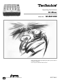
SH-MZ1200
RQT7230-Y
DJ Mixer
PP
Before connecting, operating or adjusting this product, please read these
instructions completely.
Please keep this manual for future reference.
This manual was printed with soy based ink.
The photograph shows the silver model.
RQT7230
2
Dear customer
Thank you for purchasing this product.
For optimum performance and safety, please read these instructions
carefully.
Table of contents
Supplied accessories ................................................................... 2
IMPORTANT SAFETY INSTRUCTIONS ....................................... 3
Product service ............................................................................. 4
Main features ................................................................................ 4
Component part names ............................................................... 5
Connections .................................................................................. 7
Output side connections ............................................................ 7
Input side connections ............................................................... 8
Mixing (Basic operations) ........................................................... 9
Using the microphone .............................................................. 10
Recording and playing on external equipment ........................ 10
Additional mixing operations .................................................... 11
Adjusting the effect ................................................................... 11
Adjusting the monitor ................................................................ 11
Using play mode functions ....................................................... 12
Individually adjusting the left (L) and right (R) input ............... 12
Output separation (dual output separation) ............................ 12
Fader start function .................................................................... 13
Start using the channel fader ................................................... 13
Start using the cross fader ....................................................... 13
Block diagram ............................................................................. 14
Specifications ............................................................................. 15
Maintenance ................................................................................ 15
Troubleshooting guide ............................................................... 15
Warranty (U.S.A.) ......................................................... Back cover
Supplied accessories
Please check and identify the supplied
accessories.
Use numbers indicated in parentheses when
asking for replacements parts.
In U.S.A. to order accessories, refer to
“Accessory Purchases” on back cover.
The model number and serial number of this product can be found
on either the back or the bottom of the unit.
Please note them in the space provided below and keep for future
reference.
MODEL NUMBER
SH-MZ1200
SERIAL NUMBER
CAUTION!
DO NOT INSTALL OR PLACE THIS UNIT IN A
BOOKCASE, BUILT-IN CABINET OR IN
ANOTHER CONFINED SPACE. ENSURE THE
UNIT IS WELL VENTILATED. TO PREVENT
RISK OF ELECTRIC SHOCK OR FIRE HAZARD
DUE TO OVERHEATING, ENSURE THAT
CURTAINS AND ANY OTHER MATERIALS DO
NOT OBSTRUCT THE VENTILATION VENTS.
User memo:
DATE OF PURCHASE
DEALER NAME
DEALER ADDRESS
TELEPHONE NUMBER
AC power supply cord (K2CB2CB00006) ..................... 1
Note
The included AC power supply cord is for use with this unit only.
Do not use it with other equipment.
WARNING:
TO REDUCE THE RISK OF FIRE, ELECTRIC
SHOCK OR PRODUCT DAMAGE, DO NOT
EXPOSE THIS APPARATUS TO RAIN,
MOISTURE, DRIPPING OR SPLASHING AND
THAT NO OBJECTS FILLED WITH LIQUIDS,
SUCH AS VASES, SHALL BE PLACED ON THE
APPARATUS.
The lightning flash with arrowhead symbol, within
an equilateral triangle, is intended to alert the user
to the presence of uninsulated “dangerous voltage”
within the product’s enclosure that may be of suffi-
cient magnitude to constitute a risk of electric shock
to persons.
CAUTION
CAUTION: TO REDUCE THE RISK OF ELECTRIC
SHOCK, DO NOT REMOVE SCREWS.
NO USER-SERVICEABLE PARTS
INSIDE.
REFER SERVICING TO QUALIFIED
SERVICE PERSONNEL.
The exclamation point within an equilateral triangle
is intended to alert the user to the presence of
important operating and maintenance (servicing)
instructions in the literature accompanying the
appliance.
RISK OF ELECTRIC SHOCK
DO NOT OPEN
Although the AC power switch is in the “OFF” position, the
unit is not completely disconnected from the mains. Remove
the plug from the main electrical outlet if you will not be
using the unit for an extended period of time. Place the unit
so the plug can be easily removed.

RQT7230
3
Read these operating instructions carefully before using the unit. Follow the safety instructions on the unit and the applicable safety instructions
listed below. Keep these operating instructions handy for future reference.
1) Read these instructions.
2) Keep these instructions.
3) Heed all warnings.
4) Follow all instructions.
5) Do not use this apparatus near water.
6) Clean only with dry cloth.
7) Do not block any ventilation openings. Install in accordance with
the manufacturer’s instructions.
8) Do not install near any heat sources such as radiators, heat reg-
isters, stoves, or other apparatus (including amplifiers) that pro-
duce heat.
9) Do not defeat the safety purpose of the polarized or grounding-
type plug. A polarized plug has two blades with one wider than
the other. A grounding-type plug has two blades and a third
grounding prong. The wide blade or the third prong are provided
for your safety. If the provided plug does not fit into your outlet,
consult an electrician for replacement of the obsolete outlet.
10) Protect the power cord from being walked on or pinched particu-
larly at plugs, convenience receptacles, and the point where
they exit from the apparatus.
11) Only use attachments/accessories specified by the manufac-
turer.
12) Use only with the cart, stand, tripod, bracket, or
table specified by the manufacturer, or sold with
the apparatus. When a cart is used, use caution
when moving the cart/apparatus combination to
avoid injury from tip-over.
13) Unplug this apparatus during lightning storms or when unused
for long periods of time.
14) Refer all servicing to qualified service personnel. Servicing is
required when the apparatus has been damaged in any way,
such as power-supply cord or plug is damaged, liquid has been
spilled or objects have fallen into the apparatus, the apparatus
has been exposed to rain or moisture, does not operate normal-
ly, or has been dropped.
IMPORTANT SAFETY INSTRUCTIONS
CAUTION:
This equipment has been tested and found to comply with
the limits for a Class B digital device, pursuant to Part 15 of
the FCC Rules.
These limits are designed to provide reasonable protection
against harmful interference in a residential installation.
This equipment generates, uses and can radiate radio
frequency energy and, if not installed and used in
accordance with the instructions, may cause harmful
interference to radio communications. However, there is no
guarantee that interference will not occur in a particular
installation. If this equipment does cause harmful
interference to radio or television reception, which can be
determined by turning the equipment off and on, the user is
encouraged to try to correct the interference by one or more
of the following measures:
¡Reorient or relocate the receiving antenna.
¡Increase the separation between the equipment and re-
ceiver.
¡Connect the equipment into an outlet on a circuit different
from that to which the receiver is connected.
¡Consult the dealer or an experienced radio/TV technician
for help.
Any unauthorized changes or modifications to this
equipment would void the user’s authority to operate this
device.
This device complies with Part 15 of the FCC Rules.
Operation is subject to the following two conditions: (1) This
device may not cause harmful interference, and (2) this
device must accept any interference received, including
interference that may cause undesired operation.
THE FOLLOWING APPLIES ONLY IN THE U.S.A.
RQT7230
4
Main features
Listening caution
Selecting fine audio equipment such as the unit you’ve just pur-
chased is only the start of your musical enjoyment. Now it’s time
to consider how you can maximize the fun and excitement your
equipment offers. This manufacturer and the Electronic Industries
Association’s Consumer Electronics Group want you to get the
most out of your equipment by playing it at a safe level. One that
lets the sound come through loud and clear without annoying
blaring or distortion—and, most importantly, without affecting your
sensitive hearing.
We recommend that you avoid prolonged exposure to excessive
noise.
Sound can be deceiving. Over time your hearing “comfort level”
adapts to higher volumes of sound. So what sounds “normal” can
actually be loud and harmful to your hearing.
Guard against this by setting your equipment at a safe level
BEFORE your hearing adapts.
To establish a safe level:
¡Start your volume control at a low setting.
¡Slowly increase the sound until you can hear it comfortably and
clearly, and without distortion.
Once you have established a comfortable sound level:
¡Set the dial and leave it there.
Taking a minute to do this now will help to prevent hearing
damage or loss in the future. After all, we want you listening for a
lifetime.
E
L
E
C
T
R
O
N
I
C
I
N
D
U
S
T
R
I
E
S
•
A
S
S
O
C
I
A
T
I
O
N
•
EST. 1924
Product service
1. Damage requiring service—The unit should be serviced by
qualified service personnel if:
(a) The AC power supply cord or AC adaptor has been
damaged; or
(b) Objects or liquids have gotten into the unit; or
(c) The unit has been exposed to rain; or
(d) The unit does not operate normally or exhibits a marked
change in performance; or
(e) The unit has been dropped or the cabinet damaged.
2. Servicing—Do not attempt to service the unit beyond that
described in these operating instructions. Refer all other servic-
ing to authorized servicing personnel.
3. Replacement parts—When parts need replacing ensure the
servicer uses parts specified by the manufacturer or parts that
have the same characteristics as the original parts.
Unauthorized substitutes may result in fire, electric shock, or
other hazards.
4. Safety check—After repairs or service, ask the servicer to
perform safety checks to confirm that the unit is in proper
working condition.
Product information
For product information or assistance with product operation:
In the U.S.A., refer to “Customer Services Directory” on back cover.
In Canada, contact the Panasonic Canada Inc. Customer Care Centre
at 905-624-5505, or visit the website (www.panasonic.ca), or an
authorized Servicentre closest to you.
A 4 channel universal type DJ oriented DJ mixer providing new audio
performance and functional with the Technics SL-DZ1200 direct drive
digital turntable (Not included) hereinafter referred to as the digital
turntable.
Robust basic functions
Input-output features
•12 input terminals are available, 2 for CD/LINE input, 3 for LINE
input, 3 for PHONO input, 2 for microphone input and 2 for digital
input.
•Digital output, audio recording output, monitor output, headphone
output, master 1 and 2 output, and a pro-spec engineered XLR
terminal which all function independently.
•An EFFECT SEND, EFFECT RETURN terminals have also been
added for use with an external effector.
3 Band equalizer for sound-source level
•A HIGH, MID, LOW equalizer is provided for each channel. A wide
variety of possibilities are provided for sound as the attenuation
range is set to a high -24 dB (12 dB/oct).
Robust monitor features for play
•Monitoring of the desired channel can be done quickly now that a
CUE button has been added to each channel and to the effect
function.
•Using the MONITOR MIXING control knob you can mix the master
output and the channel selected with the CUE button. Using MONO
SPLIT MODE, you can monitor master output and the selected
channel split separately into the left and right channels.
Support for an external effector
•You can turn EFFECT on and off for each channel. Select PRE or
POST connection for the effector and adjust the SEND, RETURN
level control.
Digitally controlled fader components that are robust and
functional
•A C. FADER CURVE switch has been added to the cross fader to
provide 3 new types of cross fader curve settings.
•A reverse switch has been added for each channel fader and the
cross fader.
•Through the use of an engineered VCA control, volume can be
controlled with very little loss in audio quality using the channel
fader or cross fader.
•Reliability improvements have been made to the cross fader through
the adoption of optical cross fader circuits and a highly durable 45
mm stroke fader providing smooth operation.
Providing new audio performance using the channel
fader and cross fader
Use the channel fader to control the left (L) and right (R) channels
individually
•With the PLAY MODE function the selected channels can be
separated and the L or R volume can be controlled individually
using the channel fader.
Control the FRONT and REAR output for two channel output using
master 1, 2
•By turning the SEPARATE OUT switch to on, you can separate
CH1 and CH2 output to the front and CH3 and CH4 output to the
rear, providing you with new sound field performance in combination
with the feature of being able to adjust the left (L) and right (R)
channels individually.
Linked play on the connected digital turntable
Real-time start and stop control using the fader
•You start and stop the digital turntable by operating the channel
fader or cross fader when connected to a digital turntable with a
control cable.
•A maximum of 2 digital turntables can be linked digitally through 2
digital inputs.
RQT7230
5
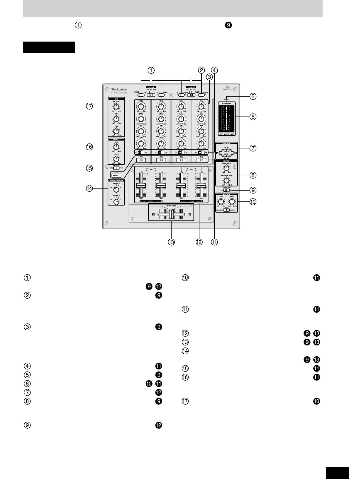
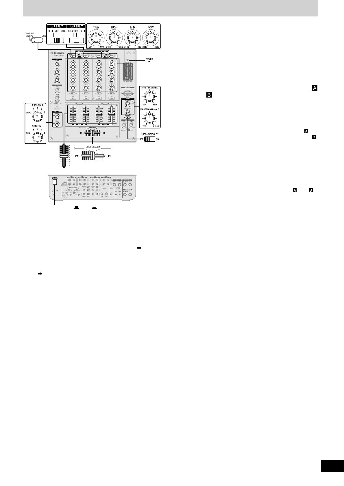
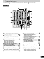
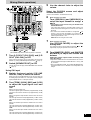
Component part names
Input switch for adjusting left and right input
individually (L/R SPLIT) ...................................
,
Input switch (CH1-CH4) ..........................................
CD/LINE DIGITAL: Line or CD input, Digital input
LINE: Line input
PHONO 1-3: Turntable phono input
Input control knob (CH1-CH4) ...............................
Input level control knob (TRIM)
High-tone input control knob (HIGH)
Mid-tone input control knob (MID)
Low-tone input control knob (LOW)
Channel effect (CH1-CH4) switch (EFFECT) ........
Power indicator lamp (POWER) ............................
Output level meter (OUTPUT LEVEL) ............ ,
Play mode lamp (PLAY MODE) ..............................
Master output control knob (MASTER) .................
Master level volume control knob (MASTER LEVEL)
Master balance control knob (MASTER BALANCE)
Output separation ON, OFF switch (SEPARATE OUT)
The unshaded numbers etc, correspond to the numbered illustrations. The shaded numbers etc, are reference pages.
Monitor control knob (MONITOR)..........................
Monitor level volume control knob (LEVEL)
Monitor mixing control knob (MIXING)
Monitor mode switch (MODE)
Monitor select button-display lamp (CUE) ...........
CH1-CH4: CH1-CH4 monitor selector
EFFECT: Effector monitor selector
Channel fader (CH1 - CH4) .............................. ,
Cross fader (CROSS FADER) ......................... ,
Cross fader Assign A, B switch
(C. FADER ASSIGN) .........................................
,
Effector output switch (PRE/POST) ......................
Input-output effect control knob (EFFECT) ..........
Output effect control knob (SEND)
Input effect control knob (RETURN)
Microphone input control knob (MIC) ...................
Microphone level volume control knob (MIC LEVEL)
High-tone microphone control knob (HIGH)
Low-tone microphone control knob (LOW)
Control panel

RQT7230
6
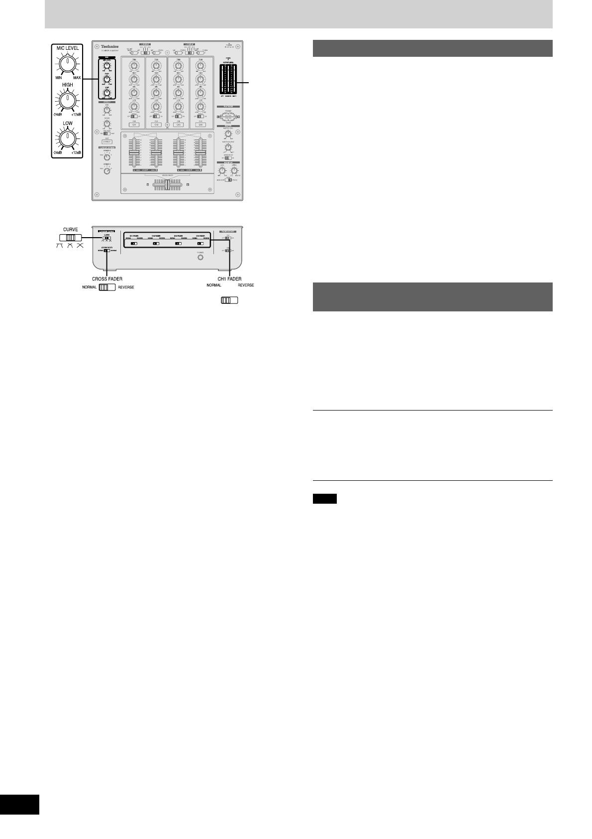
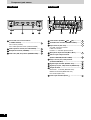
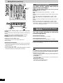
Component part names
Cross fader curve control switch
(C.FADER CURVE) ..................................................
Curve switch (CURVE)
Cross fader operation switch (CROSS FADER)
Fader operation switch (CH1-CH4 FADER) ..........
Headphone terminal (PHONES) .............................
Fader start (ON, OFF) switch (FADER START) .....
Front panel Rear panel
Power button (POWER OFF ON) ...................
Turntable earth terminal (PHONO EARTH) ...........
Input terminal (CH1-CH4) .......................................
CD/LINE: CD or line terminal
LINE: Line terminal
PHONO 1-3: Turntable phono terminal
Microphone input terminal (MIC1, MIC2) ..............
Effector input-output terminal
(EFFECT RETURN, EFFECT SEND) ......................
Player control (CH1, CH4) terminal
(PLAYER CONTROL) ..............................................
Digital output terminal (DIGITAL OUT) ..................
Digital input (CH1, CH4) terminal (DIGITAL IN) ....
Output terminal .......................................................
Master out 1, 2 terminal (MASTER OUT)
Monitor out terminal (MONITOR OUT)
Rec terminal (REC OUT)
Power input terminal (AC IN ) ............................
RQT7230
7
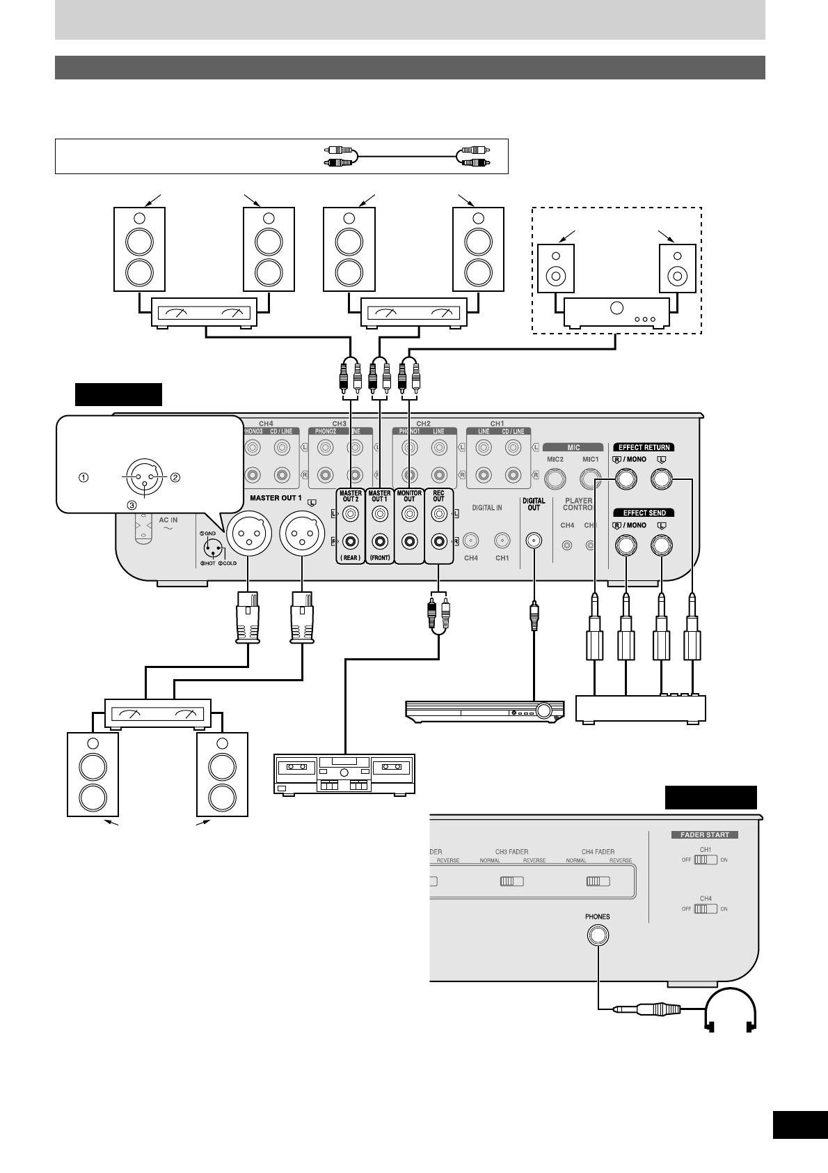
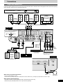
Connections
Connect the various equipment to the DJ mixer using stereo connection cables, connection cables and appropriate cables (Each sold separately).
When connecting, make sure to turn all equipment power off.
When using a monaural input effector
•Connect to the R/MONO terminal.
•The mixed left (L) and right (R) signal is output to the effector, and the left (L) and right (R) signal from the effector is input.
When listening with headphones
•Turn down the volume using the MONITOR LEVEL control knob before connecting.
•Avoid listening for prolonged periods of time to prevent hearing damage.
Speakers
(Not included)
Monitor amplifier
(Not included)
Speakers
(Not included)
Amplifier
(Not included)
Speakers
(Not included)
Amplifier
(Not included)
Rear panel
Connect when using an amplifier that
has XLR terminals. Terminal polarity is
indicated in the diagram below.
Hot (+)
Cold (–)Ground
Amplifier
(Not included)
(XLR terminal
compatible)
Speakers
(Not included)
Cassette deck (Not included)
Connection
cable
(Not included)
Type:
RCA coaxial
AV Control Receiver
(Not included)
Effector (Not included)
Connect if you want to use an
external effector or sampler etc.
to adjust the sound.
Type:
6.3 mm
(1/4 in.)
monaural
Front panel
Type:
6.3 mm (1/4 in.)
stereo
Headphone
(Not included)
Output side connections
Stereo connection cables
White (L)
Red (R)

RQT7230
8
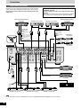
Input side connections
Connect the DJ mixer and various equipment with stereo connection
cables, control cables and connection cables (Each sold separately).
Connect the AC power supply cord after completing all the other
connections.
Note
It is not necessary to connect a grounding wire if there is no grounding terminal or grounding wire on the turntable.
Connections
Rear panel
Direct drive digital turntable 2
(Not included)
Direct drive digital turntable 1
(Not included)
Control cable
(Not included)
Type:
3.5 mm (1/8 in.)
stereo
Connect for use with
the fader start function
( page 13)
Microphone 2
(Not included)
Microphone 1
(Not included)
Type:
6.3 mm (1/4 in.) monaural
AC power
supply cord
(Included)
Household
AC outlet
Turntable 3 (Not included) Turntable 2 (Not included) Turntable 1 (Not included)
Connection cable (Not included)
Type: RCA coaxial
Direct drive digital turntable
(Not included)
Direct drive digital turntable
(Not included)
Cassette deck (Not included)
Control cable
(Not included)
Type:
3.5 mm (1/8 in.)
stereo
Connection to the SH-MZ1200 rear panel PLAYER
CONTROL terminal
Only the separately sold direct drive digital turntable can be
operated.
Connecting to control terminals of other manufacturer’s products
may result in incorrect operation or other equipment problems.
CD player 2 (Not included) CD player 1 (Not included)
Grounding
wire
Connection cable (Not included)
Type: RCA coaxial
RQT7230
9
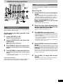
Mixing (Basic operations)
LR
L/R SPLIT
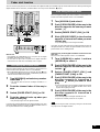
Press [POWER OFF ON]
The POWER lamp comes on after the power is turned on.
3 Switch the input switch (CD/LINE
DIGITAL, LINE) to select the source
When you select CD/LINE DIGITAL on CH1 or CH4, input can
be analog input (CD/LINE CH1, CH4 input terminal) or digital
input (DIGITAL IN CH1, CH4 input terminal).
4 Turn [TRIM], [HIGH], [MID] and [LOW]
to adjust the input signal level and
sound
TRIM:
Adjusts the input signal level.
Turn to the right for higher sound level (to approximately +8 dB)
Turn to the left for lower sound level (to approximately –8 dB)
HIGH:
Adjusts the high tone input sounds. Sound is flat at the center
position.
Turn to the right to increase sound (to approximately +12 dB at 10 kHz)
Turn to the left to decrease sound (to approximately –24 dB at 10 kHz)
MID:
Adjusts the mid tone input sounds. Sound is flat at the center
position.
Turn to the right to increase sound (to approximately +12 dB at 1 kHz)
Turn to the left to decrease sound (to approximately –24 dB at 1 kHz)
LOW:
Adjusts the low tone input sounds. Sound is flat at the center
position.
Turn to the right to increase sound (to approximately +12 dB at 50 Hz)
Turn to the left to decrease sound (to approximately –24 dB at 50 Hz)
5 Use the channel fader to adjust the
volume
Select the CH2-CH4 source and adjust
volume and sound
(Same as instructions 3 - 5 indicated on the left)
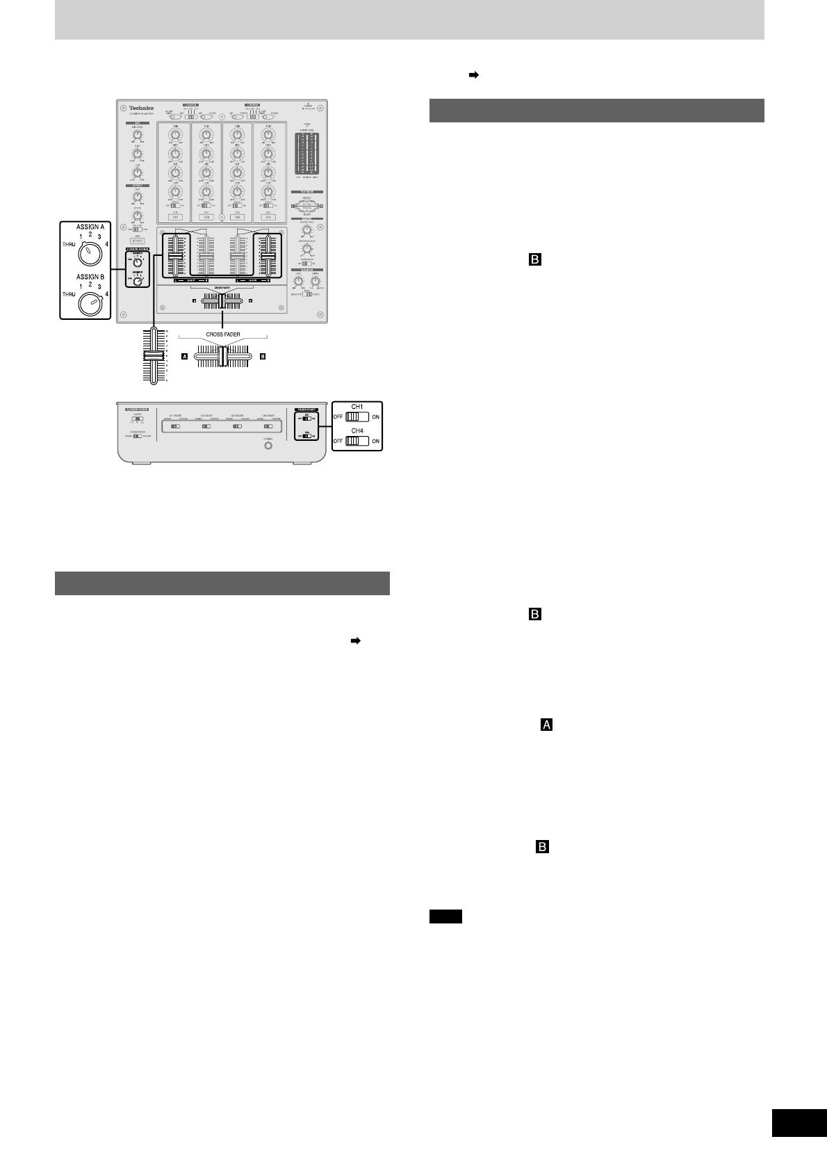
6 When using the cross fader
Turn [ASSIGN A] and [ASSIGN B] to
select the input channel to assign
and
•Select different input channels using the ASSIGN A and
ASSIGN B switches.
If the same input channel is selected by both switches, the
volume will remain unchanged even when the cross fader is
operated.
•The channel selected with ASSIGN A is assigned to , the
channel selected with ASSIGN B is assigned to .
Unassigned channels are not output through the cross fader.
1-4: Assigned channels 1 to 4
THRU: When not using the cross fader
7 When using the cross fader
Use [CROSS FADER] to adjust the
mixing level
The mixing level of the source audio assigned to and is
adjusted by varying the position of the cross fader.
8 Turn [MASTER LEVEL] and [MASTER
BALANCE] to adjust the volume and
balance
Adjust the master output volume and left (L) and
right (R) balance.
•Input source audio from the selected channels CH1-CH4 is
mixed and output through the MASTER OUT 1 left (L) and
(R) terminals.
•Even if the MASTER LEVEL or the MASTER BALANCE is
changed the REC OUT or DIGITAL OUT output does not
change.
1 Turn [L/R SPLIT (CH1 CH2)] and [L/R
SPLIT (CH3 CH4)] to OFF
Select CH1 or CH2 input, CH3 or CH4 input to use the PLAY
MODE's (L) and (R) individual adjustment feature ( page 12).
Using CH1 input
2 Switch [SEPARATE OUT] to OFF
Turn on to activate the play mode SEPARATE OUT function
(
page 12).
RQT7230
10
Using the microphone
Turn [MIC LEVEL], [HIGH] and [LOW] to
adjust volume and sound
Adjusts the microphone volume and sound connected
to MIC 1 and MIC 2 terminals.
MIC LEVEL:
Adjusts the microphone volume (Attenuation: – ∞ to 0 dB)
HIGH:
Adjusts the high tone microphone sound. Sound is flat at the center
position.
Turn to the right to increase (to approximately +12 dB at 10 kHz)
Turn to the left to decrease (to approximately –24 dB at 10 kHz)
LOW:
Adjusts the low tone microphone sound. Sound is flat at the center
position.
Turn to the right to increase (to approximately +12 dB at 100 Hz)
Turn to the left to decrease (to approximately –24 dB at 100 Hz)
•Input of MIC 1 and MIC 2 is mixed and output through the MASTER
OUT 1 left (L) and right (R) terminals.
Note
The channel fader and cross fader used with this unit are designed
for extended use however, depending on the way they are being used
(e.g. quick, repetitive movements such as Hip Hop transfer play,etc.)
replacement may be necessary.
•Contact your nearest dealer to have your channel fader and or
cross fader replaced.
•To the dealer:
The “Fader Replacement Instructions” are included with the
replacement product.
Replacement part number
Channel fader (Part No. REP3743A-S)
Cross fader (Part No. REP3742A-S)
Mixing (Basic operations)
Changing the channel fader, cross fader operation
method
Use the channel fader switch to change the operation method for each
channel.
(e.g. using CH1) Switch [CH1 FADER] and [CROSS FADER]
NORMAL: Operation is as indicated on the panel
REVERSE: Operation is reverse as indicated on the panel
Changing the cross fader curve
Select from 1 of 3 types of cross fader startup curves.
Switch [CURVE]
Output level meter display
•The mixed left (L) and right (R) volume level of the selected channel
(CH1-CH4) is displayed in the LEFT and RIGHT columns of the
output level meter.
Display range: –20 to +8 dB
•Even if the MASTER LEVEL or MASTER BALANCE is changed
the OUTPUT LEVEL meter display does not change.
OUTPUT
LEVEL
meter
Recording and playing on external
equipment
You can record and play on externally
connected equipment.
Using the REC OUT terminal
The same source as MASTER OUT 1 is output.
Using the DIGITAL OUT terminal
The same digital signal source as MASTER OUT 1 is output.
Even if the MASTER LEVEL or the MASTER BALANCE is changed
the REC OUT or DIGITAL OUT output does not change and recording
or play remains unaffected.

RQT7230
11
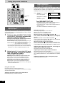
Additional mixing operations
Adjusting the monitor
You can check the sound on the headphones etc. during play and cue
the channel you want to mix, and adjust the volume and check the
mixing sound.
Monitoring CH1
1 Press [CUE CH1] to turn on the monitor
sound
•The display lamp lights once the CUE button is pressed.
•Monitor sound from the selected channel is output to
PHONES (Headphones) and MONITOR OUT terminal.
•Mixed sound can be output by pressing multiple CUE buttons.
When using an effector ( left side of this page)
Press [CUE EFFECT] to turn on the
monitor sound
•Monitor EFFECT RETURN is output.
2 Select the input, adjust the input level,
sound, and adjust the volume with the
channel fader and cross fader
( page 9, Mixing, instructions 3 - 7)
3 Turn [MIXING] and adjust mixing
•Turn completely to the right for audio from the master output.
•Turn completely to the left for audio from the channel selected
with the CUE button.
•When the control knob is in the center position the audio
level of the master output and the channel selected with the
CUE button is half and half.
•The monitor volume level is displayed in the MONITOR
column of the output level meter.
4 Switch [MODE] and select the monitor
sound
You can select the monitor sound to be stereo or split
between the channel selected with CUE button (L) and
master (R).
Select MONO SPLIT and the monitor output will become
monaural, left (L) will output audio from the channel selected
with the CUE button, and the right (R) will output audio from
the master output channel.
5 Turn [LEVEL] to adjust the monitor
volume
•Even if the MASTER LEVEL and MASTER BALANCE is
changed the monitor sound does not change.
Adjusting the effect
You can adjust the volume level and select the output point when
using an externally connected effector.
1 Switch [EFFECT] to ON
Outputs to the external effector.
2 Switch [PRE/POST] and select the
output point
PRE: Outputs before the channel fader
POST: Outputs after the channel fader
3 Turn [SEND] to adjust the output level
Adjusts the output volume level sent to the external
effector.
4 Turn [RETURN] to adjust the input level
Adjusts the input volume level from the external
effector.
•An effect is applied to the input source sound and output to
the MASTER OUT 1 terminal.
On the channel you have selected to use
effect output
OUTPUT
LEVEL
meter
Using output separation
When using output separation (dual output separation) ( page 12),
audio is output through the MASTER OUT 2 (REAR) terminal.

RQT7230
12
Using play mode functions
1 Switch to either [L/R SPLIT (CH1 CH2)]
or [L/R SPLIT (CH3 CH4)] and select the
channel to adjust individually
The input of the selected channel is allocated to
the channel to be adjusted on the panel.
CH1 or CH2 input: Left (L) is input to CH1 on the panel, right
(R) is input to CH2 on the panel.
CH3 or CH4 input: Left (L) is input to CH3 on the panel, right
(R) is input to CH4 on the panel.
•The L or R PLAY MODE lamp of the selected channel lights.
•By selecting OFF, input becomes both channels without any
separation. The L or R PLAY MODE lamp doesn’t light.
2 Adjusting left (L) and right (R) input
level and sound, and use the channel
fader to adjust the volume
( page 9, Mixing, instructions 4 - 5)
Adjusting the CH1 or CH2 level, sound, channel fader
Left (L) input: Use any of the CH1 knobs on the panel
Right (R) input: Use any of the CH2 knobs on the panel
Adjusting the CH3 or CH4 level, sound, channel fader
Left (L) input: Use any of the CH3 knobs on the panel
Right (R) input: Use any of the CH4 knobs on the panel
•Mixed source audio is output from the left (L) and right (R)
terminals of MASTER OUT 1.
Output separation
(dual output separation)
(e.g.) MASTER OUT 1 (FRONT)
terminal:
For the front speaker
MASTER OUT 2 (REAR)
terminal:
For the rear speaker
Turn [SEPARATE OUT] ON
•CH1 and CH2 input is output from the MASTER OUT 1
(FRONT) and MASTER OUT 1 (XLR) terminal.
•CH3 and CH4 input is output from the MASTER OUT 2
(REAR) terminal.
•The FRONT and REAR PLAY MODE lamps light.
Using the play mode function, by separating the left (L) and right (R)
selected input channel you can individually adjust the left (L) and right
(R) volume and sound.
L R
LR
[MASTER OUT 1]
[MASTER OUT 2]
Venue
By turning the SEPARATE OUT function ON, you can output audio
through 2 separate channels, from MASTER OUT 1 (FRONT) and
from MASTER OUT 2 (REAR). You can adjust the left and right output
individually and use the cross fader for real time play.
Using the cross fader
From Mixing on page 9, perform instructions 6-7.
Select the same channel selected above in instruction 1 for switching
ASSIGN A and ASSIGN B.
Adjusting the master output volume and balance
From Mixing on page 9, perform instruction 8.
Using the cross fader
From Mixing on page 9, perform instructions 6-7.
While the cross fader is in NORMAL position
While ASSIGN A : 1 or 2, ASSIGN B : 3 or 4
When the cross fader is moved all the way toward :
Only the source audio assigned to is output from the MASTER
OUT 1 (FRONT) and MASTER OUT 1 (XLR) left (L) and right (R)
terminals.
When the cross fader is moved all the way toward :
Only the source audio assigned to is output from the MASTER
OUT 2 (REAR) left (L) and right (R) terminals.
When the cross fader is in the center position:
Source audio assigned to is output through the MASTER OUT 1
(FRONT) and MASTER OUT 1 (XLR) terminals, and source audio
assigned to is output through the MASTER OUT 2 (REAR) terminal.
Adjusting the input level and sound, and using the
channel fader to adjust the volume
From Mixing on page 9, perform instructions 4-5.
Adjusting the master output volume and balance
From Mixing on page 9, perform instruction 8.
Adjust the volume and left (L) and the right (R) balance of the MASTER
OUT 1 (FRONT), MASTER OUT 1 (XLR) and MASTER OUT 2 (REAR)
output.
Adjusting individually of left (L) and right (R) input
Perform instructions 1-2 on the left.
PLAY MODE
lamp
Individually adjusting the left (L) and
right (R) input
RQT7230
13
Fader start function
You can start music play from the SL-DZ1200 direct drive digital turntable (not included) using the channel fader and cross fader by connecting the
digital turntables to CH1 and CH4. (A control cable is necessary for this connection.
page 8)
3 Switch [FADER START (CH1)] to ON
1 Turn [ASSIGN A] and select any number
other than 1
•The channel fader will not start the digital turntable if 1 is
selected.
2 Push the channel fader all the way to
zero
4 Push the channel fader up when you
want to start play
•Play instantly begins from the digital turntable.
Start using the channel fader
If you push the channel fader back to the original position (zero) after
play on the digital turntable has started, the digital turntable returns to
the set point and waits in the standby position.
3 Switch [FADER START (CH1)] to ON
1 Turn [ASSIGN A] and select 1
2 Push [CROSS FADER] all the way in the
direction opposite the source you want
to start ( )
Start using the cross fader
If you push the cross fader back to the original position after play on
the digital turntable has started, the digital turntable returns to the set
point and waits in the standby position.
4 Slide [CROSS FADER] in the direction
opposite of instruction 2 when you want
to start play
•Play instantly begins from the digital turntable.
Alternate play of two digital turntables connected to CH1
and CH4
When the cross fader operation switch is set to NORMAL.
3 Switch [FADER START (CH1)] and
[FADER START (CH4)] to ON
1 Turn [ASSIGN A] to select 1 and turn
[ASSIGN B] to select 4
4 Push [CROSS FADER] all the way in the
direction opposite of instruction 2
(towards ), when you want to start
play
•Play instantly begins from the digital turntable connected to
CH1. (At the same time, the digital turntable returns to the
set point when playing on CH4)
5 Push [CROSS FADER] all the way in the
direction opposite of instruction 4
(towards )
•Play instantly begins from digital turntable on CH4.
•Play on CH1 instantly returns to the set point.
When the digital turntable you want to control is connected to CH1
and the channel fader operation switch is set to NORMAL.
•When individually adjusting the left (L) and right (R) input ( page
12), perform the following instructions simultaneously for the CH1
and CH2 channel faders on the panel.
When the digital turntable you want to control is connected to CH1
and the cross fader operation switch is set to NORMAL.
Before use
•Turn [MODE] to TURNTABLE on the rear panel of the digital
turntables connected to CH1 and CH4.
•Set the auto cue point and cue point on the digital turntables
connected to CH1 and CH4, and standby at the set point.
Note
While you are using the fader to start play, turning the unit off and on
may stop or start the digital turntable.
2 Push [CROSS FADER] all the way in the
direction opposite the source you want
to start ( )

RQT7230
14
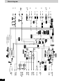
Block diagram
CH FADER
CH1-CH4
MONITOR
LEVEL
RETURN
CUE
ON/OFF
CD/LINE
LINE PHONO
CH1-CH4
EFFECT PRE/POST
MASTER BAL.
MASTER
OUT 1 (XLR)
(BAL.OUT)
MASTER
OUT 2
(REAR)
MASTER
OUT 1
(FRONT)
REC OUT
DIGITAL
OUT
MASTER LEVEL
C.FADER
NORMAL/REV.
CROSS FADER
NORMAL/REV.
CH1-CH4
C.FADER
CURVE TYPE
PHONO EQ
LINE
LINE
CD/LINE
PHONO 1
DIGITAL
IN
CH1
DIGITAL
IN
CH4
CH2
CH3
CH1
TRIM
CH1-CH4
DAI
Receiver
DAC
HIGH/
MID/LOW
CH1-CH4
L/R
SPLIT
ON/OFF
L/R
SPLIT
ON/OFF
EFFECT
RETURN
MIC1
MIC2
MIC LEVEL
ANALOG SWITCH
ANALOG SWITCH
EFFECT MIX
CHANGE
PHASE
Master-Lch/
Cue-mix
Cue-Rch/
Master-mix
Cue-Lch
Master-Rch
EFFECT
SEND
PLAYER
CONTROL
BAL. AMP
MICRO
COMPUTER
EFFECT POST
CH1
CUE MIX
MASTER MIX
L ch
R ch
CH4
L
R/MONO
CH1
L ch
R ch
SEND
OUTPUT LEVEL METER
MONITOR
OUT
PHONES
R IN
OFF
ON
Pulse trans.
L IN
MONITOR IN
SEPARATE OUT ON:
MASTER OUT1: CH1/CH2
MASTER OUT2: CH3/CH4
SEPARATE OUT OFF:
MASTER OUT1: CH1/CH2/CH3/CH4
MASTER OUT2: NO OUTPUT
PHONO EQ
PHONO EQ
LINE
PHONO 2
PHONO 3
CD/LINE
CH4
L
R/MONO
MIC AMP
EFFECT PRE
CH4
CH3
CH2
CH2
CH1
LOW
HIGH
MIC EQ
L/R PLAY
MODE ASSIGN
C.FADER
ASSIGN A/B
V.C.A
AMP
V.C.A
AMP
V.C.A
AMP
V.C.A
AMP
CH3
CH4
DAI Trans.
MONO SPLIT
MIX LEVEL
MONITOR MIX
STEREO
ADC
L ch
R ch
FRONT
MIXER
REAR
MIXER
ONOFF
FADER START
CH1,CH4
EFFECT ON/OFF
SEPARATE
OUT
ON/OFF
CHANGE
PHASE (EFFECT)
DAI
Receiver
DAC
RQT7230
15
Maintenance
To clean this unit, wipe with a soft, dry cloth.
•Never use alcohol, paint thinner, or benzine to clean this unit.
•Before using chemically treated cloth, read the instructions that came with the cloth carefully.
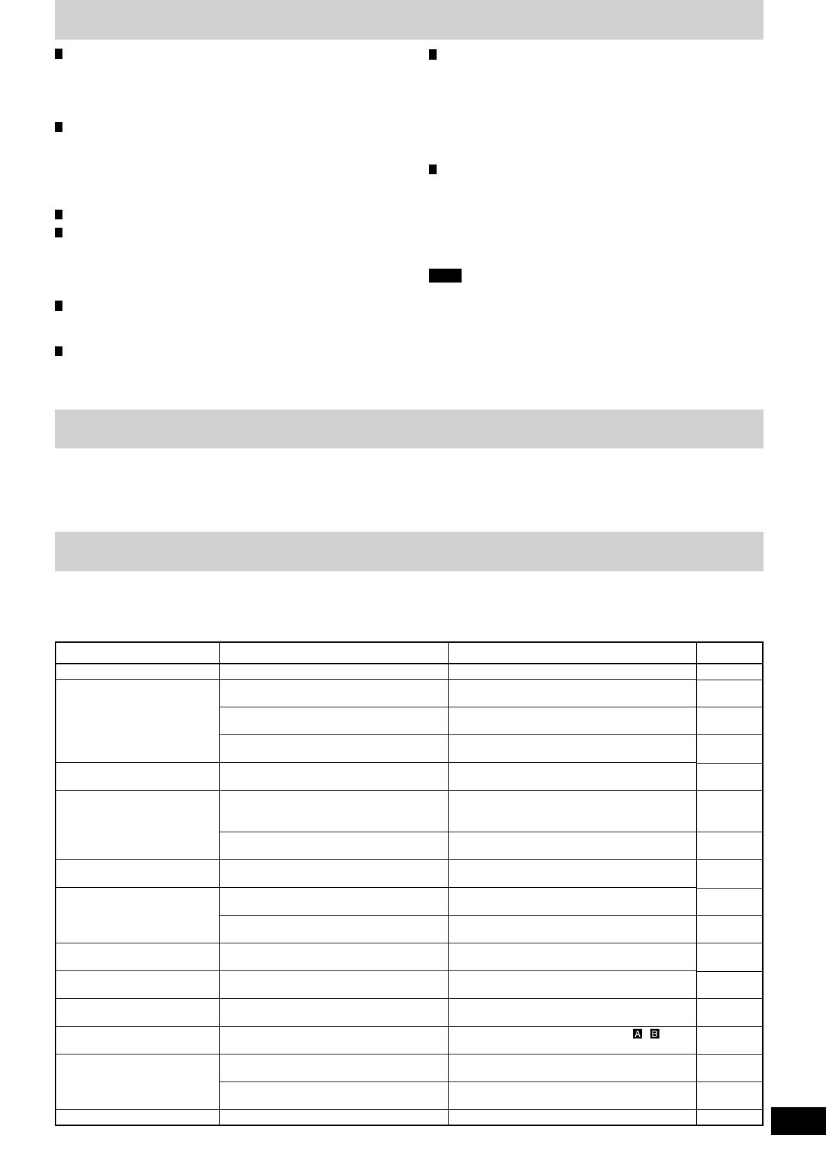
Troubleshooting guide
Before requesting service, make the below checks. If you are in doubt about some of the check points, or if the remedies indicated
in the chart do not solve the problem,
refer to the “Customer Services Directory” on back cover if you reside in the U.S.A., or refer to the “Product information” on page 4 if
you reside in Canada.
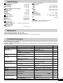
Equalizer characteristics
CD/LINE/PHONO
LOW +12 dB, –24 dB (50 Hz)
MID +12 dB, –24 dB (1 kHz)
HIGH +12 dB, –24 dB (10 kHz)
MIC
LOW +12 dB, –24 dB (100 Hz)
HIGH +12 dB, –24 dB (10 kHz)
General
Power supply AC 120 V, 60 Hz
Power consumption 35 W
Dimensions (WxHxD) 300 mm x 103 mm x 330 mm
(11
26
/
32
˝ X 4
1
/
16
˝ X 13˝)
Mass 5.3 kg
(11.7 lb.)
Note
Specifications are subject to change without notice.
Mass and dimensions are approximate.
Specifications
Input sensitivity/input impedance
PHONO (TRIM center) 2.5 mV/47 kΩ
LINE (TRIM center) 250 mV/10 kΩ
EFFECT RETURN 250 mV/47 kΩ
MIC 0.7 mV/1 kΩ
Rated output voltage/Output impedance
MASTER 1, 2 (RCA) 1 V/600 Ω
MASTER 1 (XLR) 1 V/600 Ω
MONITOR 1 V/1 kΩ
REC OUT 250 mV/1 kΩ
EFFECT SEND 250 mV/1 kΩ
Headphone output 30 mW/32 Ω
Frequency response
MASTER 1, 2 20 Hz to 20 kHz
REC OUT 20 Hz to 20 kHz
EFFECT RETURN 20 Hz to 20 kHz
MIC 20 Hz to 20 kHz
Digital audio input
Coaxial digital input
Compatible sampling rate 48 kHz/44.1 kHz/32 kHz (PCM)
Digital audio output
Coaxial digital output
Sampling rate 44.1 kHz (PCM)
Page Reference
8
9
7 - 8
9 - 10
7 - 8
—
8
10
9, 11
9
11
11
10
9
13
8
12
Action
Connect the power plug securely.
Check the source and set the control to the
proper position.
Connect the units properly.
Adjust the volume level controls correctly.
Connect the channels correctly.
Place the fluorescent light, other appliances or
their power cables as far away from the unit as
possible.
Connect the grounding wire securely.
Replace with a new fader.
Contact your nearest dealer.
Adjust the MASTER LEVEL or MONITOR LEVEL
control knobs.
Reduce the level by turning the TRIM control
knob.
Reduce the external effector's output level by
adjusting the SEND or RETURN control knob.
Turn the EFFECT switch ON for the channel to
be used.
Turn switch to the NORMAL position.
Select the input source assigned to , .
Turn ON the FADER START switch for the
channel to be used.
Use a control cable to connect the digital turntable
to the mixer.
Switch the SEPARATE OUT switch to ON.
Check
Has the power plug been disconnected?
Has the input switch been set to another
source?
Have any of the units been wrongly
connected?
Is the master level control or other volume
level controls at the MIN position?
Have you connected with the left and right
terminals reversed?
Is there a fluorescent light or other electrical
appliances, or are their power cables near
any of the connecting cables?
Has the turntable’s grounding wire been
disconnected?
Is one of the faders worn out?
Is the master volume level or monitor volume
level too high?
Is the input level too high?
Is the input level from the external effector
too high?
Is the EFFECT switch OFF?
Is the fader operation switch in the
REVERSE position?
Are the ASSIGN A and ASSIGN B switch
settings wrong?
Is the FADER START switch OFF?
Are the digital turntable and mixer connected
using a control cable?
Is the SEPARATE OUT switch OFF?
Problem
No power.
No sound even when the
power is on.
The volume is low.
Left and right sound is
reversed.
Low hum or buzz is heard
during play.
Fader (control slider) does
not move smoothly.
Sound is distorted.
External effector's sound is
distorted.
Effect does not appear to be
working.
Fader operation is reversed.
Cannot use the cross fader.
Cannot start the digital
turntable with the fader.
Output is not separated.

RQT7230-Y
M0404TK0
Panasonic Consumer Electronics
Company, Division of Matsushita
Electric Corporation of America
One Panasonic Way Secaucus,
New Jersey 07094
http://www.panasonic.com
2004 Matsushita Electric Industrial Co., Ltd.
Printed in Japan
En
Panasonic Sales Company,
Division of Matsushita Electric of
Puerto Rico, Inc. (“PSC”)
Ave. 65 de Infantería, Km. 9.5
San Gabriel Industrial Park, Carolina,
Puerto Rico 00985
Panasonic Canada Inc.
5770 Ambler Drive
Mississauga, Ontario L4W 2T3
www.panasonic.ca
Customer Services Directory
Accessory Purchases
Obtain Product Information and Operating Assistance; locate your nearest Dealer or Servicenter; purchase Parts and
Accessories; or make Customer Service and Literature requests by visiting our Web Site at:
http://www.panasonic.com/support
or, contact us via the web at:
http://www.panasonic.com/contactinfo
You may also contact us directly at:
1-800-211-PANA (7262),
Monday-Friday 9 am-9 pm; Saturday-Sunday 10 am-7 pm, EST.
For hearing or speech impaired TTY users, TTY: 1-877-833-8855
Purchase Parts, Accessories and Instruction Books online for all Panasonic Products by visiting our Web Site at:
http://www.pasc.panasonic.comm
or, send your request by E-mail to:
You may also contact us directly at:
1-800-332-5368 (Phone) 1-800-237-9080 (Fax Only) (Monday – Friday 9 am to 8 pm, EST.)
Panasonic Services Company
20421 84th Avenue South, Kent, WA 98032
(We Accept Visa, MasterCard, Discover Card, American Express, and Personal Checks)
For hearing or speech impaired TTY users, TTY: 1-866-605-1277
Matsushita Electric of Puerto Rico, Inc. Panasonic Sales Company
Factory Servicenter:
Ave. 65 de Infantería, Km. 9.5, San Gabriel Industrial Park, Carolina, Puerto Rico 00985
Phone (787)750-4300, Fax (787)768-2910
Service in Puerto Rico
(ONLY FOR U.S.A.)
Limited warranty (ONLY FOR U.S.A.)
Panasonic/Technics DJ Products
Limited Warranty
Panasonic Consumer Electronics Company,
Division of Matsushita Electric Corporation of America
One Panasonic Way Secaucus, New Jersey 07094
Panasonic Sales Company, Division of Matsushita Electric
of Puerto Rico, Inc.,
Ave. 65 de Infantería, Km. 9.5
San Gabriel Industrial Park, Carolina, Puerto Rico 00985
Limited Warranty Coverage
If your product does not work properly because of a defect in materials or workmanship,
Panasonic Consumer Electronics Company or Panasonic Sales Company (collectively
referred to as “the warrantor”) will, for the length of the period indicated on the chart below,
which starts with the date of original purchase (“warranty period”), at its option either (a)
repair your product with new or refurbished parts, or (b) replace it with a new or a
refurbished product. The decision to repair or replace will be made by the warrantor.
During the “Labor” warranty period there will be no charge for labor. During the “Parts”
warranty period, there will be no charge for parts. You must carry-in or mail-in your
product or arrange for in-home service, as applicable, during the warranty period. If non-
rechargeable batteries are included, they are not warranted. This warranty only applies to
products purchased and serviced in the United States or Puerto Rico. This warranty is
extended only to the original purchaser of a new product which was not sold “as is”.
A
purchase receipt or other proof of the original purchase date is required for warranty service.
Carry-In, Mail-in or In-Home Service
For Carry-In, Mail-in or In-Home Service (as applicable) in the United States call 1-800-
211-PANA(7262) or visit Panasonic Web Site: http://www.panasonic.com
For assistance in Puerto Rico call Panasonic Sales Company (787)-750-4300 or fax
(787)-768-2910.
In-Home service, if applicable, requires clear, complete and easy access to the product by
the authorized servicer and does not include removal or re-installation of an installed
product. It is possible that certain in-home repairs will not be completed in-home, but will
require that the product, or parts of the product, be removed for shop diagnosis and/or
repair and then returned.
Limited Warranty Limits And Exclusions
This warranty ONLY COVERS failures due to defects in materials or workmanship, and
DOES NOT COVER normal wear and tear or cosmetic damage. The warranty ALSO
DOES NOT COVER damages which occurred in shipment, or failures which are caused
by products not supplied by the warrantor, or failures which result from accidents, misuse,
abuse, neglect, mishandling, misapplication, alteration, faulty installation, set-up
adjustments, misadjustment of consumer controls, improper maintenance, power line
surge, lightning damage, modification, rental use of the product, service by anyone other
than a Factory ServiCenter or other Authorized Servicer, or damage that is attributable to
acts of God.
THERE ARE NO EXPRESS WARRANTIES EXCEPT AS LISTED UNDER “LIMITED
WARRANTY COVERAGE”. THE WARRANTOR IS NOT LIABLE FOR INCIDENTAL
OR CONSEQUENTIAL DAMAGES RESULTING FROM THE USE OF THIS PRODUCT,
OR ARISING OUT OF ANY BREACH OF THIS WARRANTY, INCLUDING WITHOUT
LIMITATION, LOSS OF GOODWILL, PROFITS OR REVENUE, LOSS OF USE OF THIS
PRODUCT OR ANY ASSOCIATED EQUIPMENT, COST OF SUBSTITUTE
EQUIPMENT, DOWNTIME COSTS, OR CLAIMS OF ANY PARTY DEALING WITH
BUYER FOR SUCH DAMAGES. (As examples, this excludes damages for lost time, cost
of having someone remove or re-install an installed unit if applicable, travel to and from
the servicer, loss of media, data or other memory content. The items listed are not
exclusive, but are for illustration only.) ALL EXPRESS AND IMPLIED WARRANTIES,
INCLUDING THE WARRANTY OF MERCHANTABILITY, ARE LIMITED TO THE
PERIOD OF THE LIMITED WARRANTY.
Some states do not allow the exclusion or limitation of incidental or consequential
damages, or limitations on how long an implied warranty lasts, so the exclusions may not
apply to you.
This warranty gives you specific legal rights and you may also have others rights which
vary from state to state. If a problem with this product develops during or after the
warranty period, you may contact your dealer or ServiCenter. If the problem is not handled
to your satisfaction, then write to the warrantor's Consumer Affairs Department at the
addresses listed for the warrantor.
PARTS AND SERVICE (INCLUDING COST OF AN IN-HOME SERVICE CALL IF
APPLICABLE) WHICH ARE NOT COVERED BY THIS LIMITED WARRANTY ARE
YOUR RESPONSIBILITY.
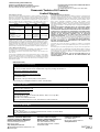
Labor
One (1) Year
Ninety (90) Days
(when applicable)
Not Applicable
(in exchange for
defective item)
Product
DJ Turntables (analog), DJ Mixers,
DJ Direct Drive Digital Turntables
Accessories:
(Repaired or exchanged)
DJ Headphones, Cartridges,
Microphones
Accessories:
(Exchanged)
SD Memory Cards, Platter
Mats, Adaptors, Cables
Service
Carry-In or Mail-In
Carry In or Mail In
Carry In or Mail In
Parts
One (1) Year
Ninety (90) Days
Ninety (90) Days
-
 1
1
-
 2
2
-
 3
3
-
 4
4
-
 5
5
-
 6
6
-
 7
7
-
 8
8
-
 9
9
-
 10
10
-
 11
11
-
 12
12
-
 13
13
-
 14
14
-
 15
15
-
 16
16


Panasonic RQT7230-3Y Owner's manual
- Category
- Supplementary music equipment
- Type
- Owner's manual
Ask a question and I''ll find the answer in the document
Finding information in a document is now easier with AI
Related papers
-
Panasonic RQT7230-3Y User manual
-
-
-
-
-
-
-
-