Baumer GXP8W - DeviceNet Installation and Operating Instructions
- Type
- Installation and Operating Instructions
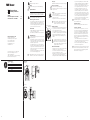
Baumer GXP8W - DeviceNet is an absolute encoder designed for precise angular position and revolution measurement. It converts measurements into electrical output signals for subsequent devices. Key features include:
- Absolute position sensing, eliminating the need for homing or referencing
- DeviceNet communication interface for easy integration into industrial networks
- Robust construction with IP65 protection, suitable for harsh industrial environments
- Compact design with multiple mounting options
- Advanced diagnostics for easy troubleshooting
- Wide range of resolutions and shaft options available to suit specific application requirements


-
 1
1
-
 2
2


Baumer GXP8W - DeviceNet Installation and Operating Instructions
- Type
- Installation and Operating Instructions
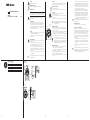
Baumer GXP8W - DeviceNet is an absolute encoder designed for precise angular position and revolution measurement. It converts measurements into electrical output signals for subsequent devices. Key features include:
- Absolute position sensing, eliminating the need for homing or referencing
- DeviceNet communication interface for easy integration into industrial networks
- Robust construction with IP65 protection, suitable for harsh industrial environments
- Compact design with multiple mounting options
- Advanced diagnostics for easy troubleshooting
- Wide range of resolutions and shaft options available to suit specific application requirements
Ask a question and I''ll find the answer in the document
Finding information in a document is now easier with AI
in other languages
- Deutsch: Baumer GXP8W - DeviceNet
Related papers
-
Baumer GXMMW Installation and Operating Instructions
-
-
-
-
-
-
-
-
-
Baumer GBM2W Installation and Operating Instructions