Baumer VCXU-25M Quick start guide
- Category
- Security camera accessories
- Type
- Quick start guide

Safety
Conformity
We declare, under our sole responsibility, that the
described Baumer VCXU cameras conform with the
directives of the CE.
All VCXU cameras comply with the recommendation
of the European Union concerning RoHS Rules.
Several of the described Baumer VCXU cameras
conform with the directives of the Korean Conformity.
Please refer for the User’s guide or technical
documentation.
Safety precautions
Notice
See the User's Guide for the
complete safety instructions!
Caution
Observe precautions for
handling electrostatically
sensitive devices!
▪ Protect the sensor from dirt and
moisture.
▪ Do not allow the camera to become
contaminated with foreign objects.
Environmental Requirements
Storage temp. -10 °C ... +70 °C
Operating temp. see Heat Trans-
mission
Humidity 10 % ... 90 %
Non-condensing
Quick Start Guide
VCXU cameras (USB 3.0)
System requirements
Single-camera system
Recommended
Multi-camera system
Recommended
CPU
Intel
®
Core
™
i5-2520M
CPU @ 2.50 GHz, Cores: 4
Intel
®
Core
™
i7-3770
CPU @ 3.40 GHz, Cores: 8
RAM 4 GB 8 GB
Operating
system
(OS)
Microsoft
®
Windows
®
7 32 / 64 bit systems (required for USB 3.0)
Microsoft
®
Windows
®
8 32 / 64 bit systems (required for USB 3.0)
Microsoft
®
Windows
®
10 32 / 64 bit systems (required for USB 3.0)
Product specication
VCXU cameras – Integrating essential basic functionalities
▪ up to 20 Megapixel
▪ up to 891 fps
▪ 29 × 29 mm housing with all-sided M3 mount
▪ Global shutter architecture for minimized motion blur
▪ Rolling shutter sensors with Global Reset for cost effective applications
▪ Extensive functionality and high frame rates
▪ Camera temperature range up to 65 °C (149 °F)
▪ USB bus powered
▪ USB Vision
TM
standard compliant
Notice
Further technical details are available in the respective data sheets.
Installation
Lens mount
Notice
Ensure the sensor and lens are not contaminated with dust and airborne
particles when mounting the support or the lens to the device!
The following points are very important:
▪ Install the camera in an environment that is as dust free as possible!
▪ Keep the dust cover (bag) on the camera for as long as possible!
▪ Hold the camera with the sensor downwards if the sensor is uncovered.
▪ Avoid contact with any of the camera‘s optical surfaces!
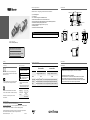
Dimensions
29
29
20
18
6,15
8,2
6
20
3
28,7
20
22
30
C-mount
6,6 ±0,3537,88,9
3
8 x M3 x 4
2 x M3 x 4
ø
Further Information
For further information about our products, please visit www.baumer.com
For technical issues, please contact our technical support:
[email protected] · Phone +49 (0)3528 4386-845 · Fax +49 (0)3528 4386-86
© Baumer Optronic GmbH · Badstrasse 30 · DE-01454 Radeberg, Germany
Technical data has been fully checked, but accuracy of printed matter is not guaranteed.
The information in this document is subject to change without notice.
Printed in Germany 09/19. v22 11164112
Download latest camera software:
www.baumer.com/vision/software
Download latest technical documentation:
www.baumer.com/cameras/docs

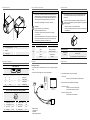
Data interface / Digital IOs
USB 3.0 (Micro B)
12345 678910
1 VBUS 6 MicB_SSTX-
2 D- 7 MicB_SSTX+
3 D+ 8 GND_DRAIN
4 ID 9 MicB_SSRX-
5 GND 10 MicB_SSRX+
Digital IOs (on camera side)
wire colors of the connecting cable (ordered separately)
8
5
7
3
1
4
2
6
1 GPIO (Line2) white 5 Power V
CC
OUT1 grey
2 not connected brown 6 OUT1 (Line3) pink
3 IN1 (Line0) green 7 GND GPIO blue
4 GND IN1 yellow 8 GPIO (Line1) red
General description
2
43
1
No. Description No. Description
1 Lens mount (C-mount) 4 LED
2 Digital IO
3 USB 3.0 port
Images with USB 2.0 / LED signals
Caution
If the camera is connected to an USB2.0 port image transmission is
disabled by default. The camera consumes more than 2.5W which
is the maximum allowed by the USB2.0 specication.But there is a
possibility to activate the image transmission at your own risk!
This activation could damage your computer´s hardware!
Procedure
1. Open the camera in the Camera Explorer.
2. Select the Prole GenICam Guru.
3. Activate the Feature USB2 Support Enable in the category
Device Control.
4. Disconnect the data connection of the camera to the USB 2.0 port.
5. Connect the data connection of the camera to the USB 2.0 port.
6. Images will be transmitted via the USB 2.0 port.
Signal Meaning
LED
green ash Power on
green USB 3.0 connection
red USB 2.0 connection
yellow Readout active
red ash Update
Installation
Installing the camera:
▪ Connect the camera to the USB connection on your PC using an appropriate
cable.
▪ If required, connect a trigger and / or flash to the digital IOs.
open wire
Installation example
1 - PCI USB board
2 - USB cable
3 - Cable for trigger and ash
Troubleshooting
1. Check camera operation using the LED signals.
→ If LED is red:
• Camera is connected to USB 2.0 (settings possible).
2. Check connection using Windows Device Manager:
→ If device is not listed:
• Check the host controller power supply.
• Check USB 3.0 cable and connection.
→ If device is regularly not listed
• Check USB 3.0 driver installation.
Heat transmission
Caution
Heat can damage the camera. Heat must be dissipated adequately
to ensure that the temperature does not exceed the values in the
table below.
As there are numerous possibilities for installation, Baumer recom-
mends no specic method for proper heat dissipation, but suggest the
following principles:
▪ operate the cameras only in mounted condition
▪ mounting in combination with forced convection may provide proper
heat dissipation
T
Measurement point Maximum temperature
Measurement
point (T)
65 °C (149 °F)
60 °C (140 °F)
1
1
only VCXU-125M.R / C.R; VCXU-201M.R / C.R
-
 1
1
-
 2
2


Baumer VCXU-25M Quick start guide
- Category
- Security camera accessories
- Type
- Quick start guide
Ask a question and I''ll find the answer in the document
Finding information in a document is now easier with AI
Related papers
-
Baumer VCXU-31C Operating instructions
-
-
Baumer VEXU-24C Quick start guide
-
Baumer VEXG-52M.R User guide
-
Baumer Housing V4A IP69K Mounting Tool User guide
-
Baumer VCXG-13C Quick start guide
-
-
Baumer VLXT-123M.FO Quick start guide
-
Baumer VCXG-32M.I Quick start guide
-