
Save This Manual
For Future Reference
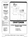
SEARS
Operators
Manual
MODEL NO.
113.198411
10" DELUXE ELECTRONIC
RADIAL SAW WITH
44" CABINET AND
2 DOORS
or
113.198611
10" DELUXE ELECTRONIC
RADIAL SAW WITH
44" CABINET AND
6 DRAWERS
Serial
Number
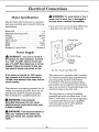
Model and serial numbers
may be found at the rear of
the base,
You should record both
model and serial number in
a safe place for future use.
CAUTION:
READ ALL
INSTRUCTIONS
CAREFULLY
\
MODEL 113.198611
MODEL 113.198411
CRRFTSMRN
10-INCH DELUXE ELECTRONIC
RADIAL SAW
• Assembly
• Operating
• Repair parts
Sold by SEARS, ROEBUCK AND CO., Chicago, IL. 60684 U.S.A.
Part No. SP5105 Printed in U.S.A.

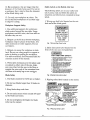
FULL ONE YEAR WARRANTY ON CRAFTSMAN RADIAL SAW
If within one year from the date of purchase, this Craftsman Radial Saw fails due to a defect in material or
workmanship, Sears will repair it, free of charge.
WARRANTY SERVICE IS AVAILABLE BY SIMPLY CONTACTING THE NEAREST SEARS SERVICE
CENTER/DEPARTMENT THROUGHOUT THE UNITED STATES.
This warranty applies only while this product is used in the United States.
This warranty gives you specific legal rights and you may also have other rights which vary from slate to state.
SEARS, ROEBUCK AND CO., DEPT. 698/731A Sears Tower, Chicago, IL 60684
_a
i i
Table of Contents
SectionTitle Page Numbers
Safety Information ............................................................................................ 3-6
Putting Your Saw Together .......................................................................... 7-30
Location and Function of Controls ........................................................... 31-34
Alignment of the Blade ............................................................................... 35-49
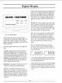
Digital Display .............................................................................................. 50-55
Electrical Connections ................................................................................ 56-57
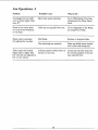
Crosscutting ................................................................................................... 58-64
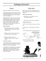
Ripping ........................................................................................................... 65-73
Cutting Accessories ...................................................................................... 74-77
Recommended Accessories .............................................................................. 78
Glossary ............................................................................................................... .79
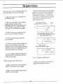
Helpful Hints ................................................................................................ 80-81
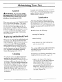
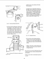
Maintaining Your Saw ................................................................................. 82-88
Changing Motor Voltage .................................................................................. 89
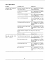
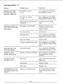
Trouble Shooting .......................................................................................... 90-95
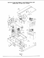
Parts Lists .................................................................................................... 96-114

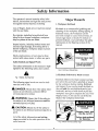
Safety Information
The operator's manual contains safety infor-
marion, instructions and signs for your protec-
tion against serious injuries, including:
Loss of fingers, hand, arm or leg from contact
with the saw blade.
Eye injuries, including being blinded from
being hit by a thrown workpiece, workpiece
chips or pieces of the saw blade.
Impact injuries, including broken bones and
internal organ damage, from being hit by a
thrown workpiece, workpiece chips or pieces
of the saw blade.
Shock, electrocution, or burn injuries from
contact with wires, motor or other saw parts.
Safety Symbol and Signal Words
The safety information in this manual is high-
lighted by the following safety alert symbol.
Fig. 1Safety Alert Symbol
The following signal words are used to indi-
cate the level of risk.
DANGER: Means that if the safety infor-
mation is not followed, someone will be
seriously injured or killed.
WARNING: Means that if the safety in-
formation is not followed someone could be
seriously injured or killed.
CAUTION: Means that if the safety in-
formation is not followed someone may be in-
jured.
All of the safety information and cutting
steps are critical to the safe operation of the
radial arm saw.
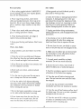
Major Hazards
1. Workpiece Kickback
Kickback is an uncontrolled grabbing and
throwing of the workpiece during ripping. If
kickback occurs, the workpiece can hit
you hard enough to cause broken bones, in-
ternal organ injury or death. To reduce or
prevent kickback, read and follow the safety
information in the Ripping section of the
manual.
Kickback.
Internal injury can
result.
Use anti-kickback
pawls/spreader.
Fig. 2 Kickback Safely Sign
2. Kickback Followed by Blade Contact
Kickback followed by blade contact can hap-
pen when the saw blade is pinched or bound
by the workpiece during ripping. Kickback
can happen if you reach around the blade to
the end with the anti-kickback pawls, (out-
feed end), and try to hold-down or pull the
workpiece through to complete the cut. Your
fingers, hand, or arm can be cut off by the
blade if the workpiece kicks back.
Kickback, Blade
Contact.
Fingers, hand, arm
can be cut off.
Follow instructions
for Ripping
Fig. 3 Blade Contact Safely Sign

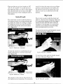
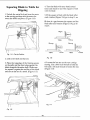
3. Wrong Way Feed
Wrong way feed is feeding the workpiece
into the end of the saw with the anti-kickback
pawls. The workpiece can be grabbed by the
blade and pull your hands into the blade
before you can let go or pull back. Fingers,
hand or arm can be cut off.
can be blinded.
Wear safety
goggles.
Wrong Way Feed.
Fingers,ban.d, arm
can De cut on.
Feed into infeed
end of saw.
Fig. 6 Safety Goggles Safety Sign
_lb DANGER: Follow the 8 steps listed
below to reduce or eliminate the risk of
being injured when using the radial arm
saw. Failure to do so can result in a life
threatening injury or death.
Fig. 4 Wrong Way Feed Safety Sign
If a workpiece is fed into the end of the saw
with the anti-kickback pawls, it can take off
like a missile. Anyone hit by the workpiece
can be killed. Feed the workpiece into the in-
feed end of the saw blade, the end that does
not have the anti-kickback pawls.
Wrong Way Feed.
Workpiece impact
can kill others.
Feed into infeed
end of saw.
Fig. 5 Wrong Way Feed Safety Sign
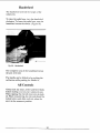
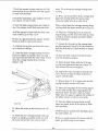
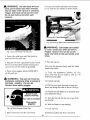
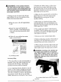
4. Thrown Workpiece Chips and Blade
Pieces
The saw can throw the workpiece, workpiece
chips or pieces of the blade violently. You
can be blinded. Wear safety goggles labeled
"ANSI Z87.1" on the package.
1. Lower the anti-kickback pawls and
spreader when crosscutting and ripping.
2. Set blade guard in horizontal position
when crosscutting.
3. Lower blade guard nose only when rip-
ping.
4. Keep hands as far away from the blade
as possible when cutting.
5. Return the saw to its rearmost position
after each crosscut.
6. Wait until the blade has stopped turn-
ing before reaching for the workpiece or
anything else on the table.
7. Read and follow the safety information
and safety instructions in the operator's
manual and in the safety labels on the
radial arm saw.
8. Know location and function of all con-
trois before using saw. See the Location
and Function of Controls section.

Personal Safety
1. Wear safety goggles labeled "ANSI Z87.1"
on the package. Do not wear regular glasses,
they are not safety glasses.
2. Wear snug fitting clothes, short sleeve
shirts and nonslip footwear. Cover up or tie
long hair. Do not wear loose, baggy clothes,
gleves, neckties, rings, watches or any other
:jewelry.
3. Wear a dust mask, with your safety gog-
gles, if cutting operation is dusty.
4. Wear hearing protectors, ear plugs or
muffs, if you use the saw daily.
5. Keep good footing and balance. Don't over-
reach.
Work Area Safety
1. Keep children, pets and visitors out of the
work area.
2. Make the work area child proof. Remove
the yellow key from the red switch and place
it out of reach and sight. Lock work area.
3. Keep floors dry and free from sawdust, wax
or other slippeu materials.
4. Keep work area clean, uncluttered and
well lighted.
5. Use the saw in a dr), area. Do not use in
wet or damp area. Do not use outside.
6. Clear the table of all ebjects (adjusting
wrenches, tools, scraps of wood etc.) except
the workpiece to be cut, fixtures or clamps
before turning the saw on.
7. Do not do layout, assembly or setup work
on the table while the blade is turning.
8. Store items away from the saw. Do not
climb on the saw to reach items. Do not
stand on the table; the saw can tip over.
Saw Safety
1. Keep guards and anti-kickback pawls in
place and in working order.
2. Check for broken or damaged parts before
using saw. A damaged guard or other saw
part should be checked for alignment, bind-
ing, breakage and correct mounting to make
sure they are working properly. Repair or
replace damaged guards or other saw parts.
3. Unplug saw before doing maintenance,
making adjustments, and changing blades and
accessories.
4. Use clamps or vice to hold workpiece
when practical. It's safer than using your
hands and frees them to operate the saw.
5. Do not force the saw, saw blade or acces-
sories to do jobs they are not designed to do.
6. Make sure the yellow key is removed and
the red switch is in the off position before
plugging in the power cord.
7. Cut only wood, woodlike or plastic
materials. Do not cut metal materials.
8. Secure the saw to floor, wall, bench or
table if it slides, tips or walks during use.
9. Feed the workpiece against the direction
of rotation of the blade when ripping.
10. Turn the saw off before leaving work
area. Do not leave the saw until the blade
has stopped.
11. Lock the rip and miter locks before
moving the saw from one location to another.
12. Turn the saw off and remove yellow key if
the blade jams. Do not try to free a jammed
workpiece with the saw on.
13. Turn the saw off if it vibrates excessively
or makes an unfamiliar noise. Correct any
problems before restarting saw.

14.Rip workpiecesthat arelonger than the
diameter of the blade beingused.Do not rip
aworkpiece that isshorter than the diameter
of thebladebeing used.
15.Cut only oneworkpiece at atime. Do
not cut stackedworkpiecesor lay them edge
to edgefor cutting.
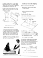
Workpiece Support Safety
1. Use additional supports for workpieces
which extend beyond the saw table. Large
workpieces can shift, twist, rise from table or
fall after they are cut.
2. Helpers can be hit by a thrown workpiece,
workpiece chips or pieces of the blade. Use
table extensions or other supports. Do not
use helpers.
3. Helpers can cause the workpiece to kick-
back. Do not use other people to support or
assist in feeding or pulling the workpiece.
Use table extensions. See Recommended Ac-
cessories section of the manual.
4. When table extensions over 24 inches wide
are added to either side of the saw, make
sure you either bolt the saw to the floor or
support the outer end of the extension from
the floor with sturdy legs or an outrigger.
Blade Safety
1. Use blades marked for 3450 rpm or higher.
2. Do not use blades larger than 10 inches in
diameter.
3. Keep blade sharp and clean.
4. Do not cycle motor switch on and off rapid-
ly; the blade can loosen.
5. Do not overtighten the blade; the blade
collar can be warped.
Safety Labels on the Radial Arm Saw
The following labels are on your radial arm
saw. Locate, read and follow the safety in-
structions and information contained in these
labels.
1. Wrong way feed label located on the out-
feed end of the blade guard.
I DANGER I
TO AVOID
INJURY DO NOT
FEED MATERIAL
INTO CUTTING
TOOL FROM
THIS END
Fig. 7 Wrong Way Feed Labe/
2. Safety instruction label located on the
front of the saw near the handwheel.
[ DANGER I
FOR YOUR OWN SAFETY:
t. Read and understand owner's manual
before operating machine.
2. Wear safety goggles complying with
ANSI Z87,1.
3. Keep hands out of path of saw blade.
4. Know how to avoid "KICKBACKS:'
5. Use "PUSH STICK" for narrow work,
6, Never reach around the saw blade.
7. Never perform any operation
"FREEHAND:'
8. Return carriage to the full rear position
after each cross-cut type operation.
9. Shut off power and allow saw blade to
stop before adjusting or servicing.
Fig. 8 Safety Instruction Label
3. Ripping safety label located on the motor.
I DANGER J WHEN RIPPING
1. R4HId =nd undlrltlnd OW._,eCS n_l_ ugl 5. UI_ "PUSH s'ncK" for narrow work.
before ng m.aehlne.
7_ NeVK rm any operatlo_
ANS_ Z87.r. "FRIErH_A_, "
3, Klmp hands out of path of imw binde. 8. Shut off power ar)d allow saw binde to
l, Know how to avoid "KICK BACKS;' stop before IKIJustir_jor _rvlclng.
cut_ t,o,_ _ THIS END ONLY
DANGER AT OUTFEED
pull han_l_ into and under _ t_
KEEP HANDS AWAY!
-- KIBEP HANDS AWAY! J _17
Motor Connected For 120 V,12 A, 60 HZ, 3450 RP M. Part816845
For 240 V, 6 A. Connect, See Own er's Manu_l. MOdel C48HX-273
Fig. 9 Ripping Safety Label

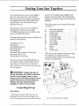
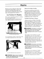
Putting Your Saw Together
,-..,
Your radial arm saw is easy to put together,
however it will take time. Ask a friend to
help, and follow these assembly instructions.
It is important for your safety, and for the
quality of your cuts, that the saw be put
together with care.
This manual was written for two different
models of the radial arm saw: model
113.198611 has drawers for the cabinet, and
model 113.198411 has doors.
The following assembly sections should be fol-
lowed for both models:
Unpacking / Set up
Information
Attaching Handwheel
Mounting Motor
Mounting Saw
Attaching Trim Ledge and Trim Caps
Mounting Table Locks
Mounting the Front Table
All other sections are labelled with the cor-
rect model number. Follow ONLY instruc-
tions that are meant for your model saw.
Both models work in the same way once they
are put together.
A
WARNING: Plugging the saw in
during assembly can result in electrical
shock or your fingers, hand, or arm
being cut off from blade contact. Do not
plug in the saw at any time during as-
sembly. The saw should only be
plugged in when it is to be used.
Unpacking/Set up
Both Models
1. Some parts of your radial arm saw are
packaged in small boxes according to func-
tion. As you unpack, try to keep the contents
of each of the smaller boxes together and
separate from the others. This will help you
identify and locate the parts you need during
assembly.
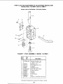
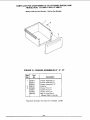
The following parts are included with model
113.198611:
A.
B.
C.
D.
E
F.
G.
H.
I.
J.
tC
L
Basic Saw Assembly ............... 1
Operator's Manual ................ 1
Cabinet Box ...................... 1
Drawer Box ...................... 1
Caster/Foot Box .................. 1
Loose Parts Bags ................. *8
Trim Caps ....................... 2
Trim Ledge ...................... 1
Rear Table ....................... 1
Spacer ........................... 1
Fence ........................... 1
Front Table ...................... 1
"This is the total number of loose parts bags.
Two of these are packed inside the
Caster/Foot Box, and four are packed inside
a larger loose parts bag.
A
C
Fig, 10 - Parts for Model 113.198611

The following parts are included with model
113.198411:
A°
B.
C.
D.
E.
F.
G.
H.
I.
J.
Basic Saw Assembly ............... 1
Operator's Manual ................ 1
Cabinet Box ...................... 1
Loose Parts Bags ................. *7
Trim Caps ....................... 2
Trim Ledge ...................... 1
Rear Table ....................... 1
Spacer ........................... 1
Fence ........................... 1
Front Table ...................... 1
*Note: This is the total number of loose parts
bags. One of these is packed inside the
Cabinet Box, and four are packed inside a
larger loose parts bag.
G
A
H
J
Fig. 11 - Parts for Model 113.198411
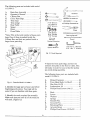
2. Identify the large parts of your saw before
beginning each section. Your task will be
easier if you are familiar with these parts.
3. Identify the tools required for assembly.
Make sure that you have all of the tools you
will need. (Figure 12)
7/16" Wrench
1/2" Wrench
9/16" Wrench
3/4" Socket
9/16" Socket
7/16" Socket
Socket Extension
Socket Wrench
Medium Screwdriver
#2 Phillips Screwdriver
Pliers
Framing Square
Pencil
1/8" Hex "L" Wrench
3/16" Hex "L" Wrench
Fig. 12 -Tools Required
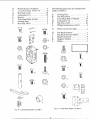
4. Open the loose parts bags, and sort the
contents into piles on the floor or table. This
will make it easier for you to find the part(s)
you need during assembly.
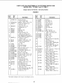
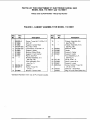
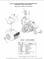
The following loose parts are included with
model 113.198611:
A.
B.
C.
D.
E.
Drawer Fasteners ................ 48
Truss Head Bolts 1/4-20xl/2 ....... 82
Hex Nuts 1/4-20 ................. 82
Lockwashers 1/4 ................. 82
Phillips Head Screws 1/4xl/2 ....... 8
F.
G.
H.
I.
J.
K.
L.
M.
N.
Rods ............................ 2
Levers ........................... 2
Washers ......................... 2
Springs .......................... 2
Smooth Pins ...................... 2
Grooved Pins ..................... 2
Retaining Plates .................. 2
Actuator Boxes ................... 2
Phillips Itead Screws 10-32x3/8 ..... 4

O,
P.
O.
R.
S.
T.
U.
V.
Slotted Screws 1/4-20x7/16 ......... 4
Truss Head Bolts I/4-20x7/16 ........ 20
Hex Nuts 1/4-20 ................. 18
Lockwashers 1/4 ................. 18
Spacers .......................... 2
Truss Head Bolts 1/4-20xl ......... 2
Leveling Feet ..................... 2
Hex Nuts 3/8-16 .................. 2
C
M
° I
i
B
F
N
U
Fig. 13 - Loose Parts, Model 113.198611
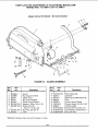
The following loose parts are included with
model 113.198411:
A.
B.
C.
D.
E.
F.
Leveling Feet ..................... 4
Hex Nuts 3/8-16 .................. 8
Truss Head Bolts 1/4-20xl/2 ....... 66
Lockwashers 1/4 ................. 66
Hex Nuts 1/4-20 ................. 66
Phillips Head Screws 1/4xl/2 ....... 8
G. Plastic Covers for J-Slots ........... 2
H°
I.
J.
K.
L.
Pan Head Screws 6 ................ 4
Pan Head Screws 6-32x3/8 ......... 4
Plastite Screws 10 ................. 8
Magnetic Catches ................. 2
Hinges ........................... 4
C
G
Fig. 14 - Loose Parts, Model 113.198411
9

The following loose parts are included with
both models:
A.
B.
Handwheel ....................... 1
Arbor Wrenches .................. 2
Ci
D.
E.
G°
H.
Jo
K.
L.
M.
N.
Yoke Plug ....................... 1
Yellow On/Off Key ............... !
Battery 6V, alkaline, size J ......... 1
Motor Support Cap ............... !
Pan Head Screw 10-32xl/2 ......... 1
Lockwasher 10 .................... 1
Battery Cover .................... 1
Locknuts 1/4-20 ................... 2
Washers 17/64x5/8x1/32 ............ 4
Hex Head Bolts 1/4-20x5/8 ......... 4
Lockwashers 1/4 .................. 4
Hex Nuts 1/4-20 .................. 2
O,
P.
O.
R.
S.
T.
U.
V.
W.
Mounting Screws 1/4-20xl-3/4 ...... 5
Washers 17/64x5/8x1/32 ............ 5
Rubber Grommets ................ 5
U-Clips 1/4-20 .................... 5
Tee Nuts ......................... 3
Leveling Screws 1/4-20x7/8 ......... 3
Pan Head Screws 1/4 x 1-1/4 ........ 4
Washers 17/64x3/4xl!16 ............ 4
White Buttons .................... 2
X.
Y.
Z.
Right Table Rail .................. 1
Left Table Rail ................... 1
Lock Handles with Rods .......... 2
II, o=
©°
I}i; R
©v
._ z %
Fig. 15 - Loose Parts, Both Models
Information
Both Models
1. If you are missing any part while putting
your saw together, do not continue assembly.
Contact your Sears Service Center or Retail
Store and get the missing part before continu-
ing assembly or trying to use the saw.
Complete parts lists are located at the end of
this manual. Use these lists to identify the
number of any missing part.
2. Sometimes small parts get lost in packag-
ing materials. Do not throw away any packag-
ing until your saw is put together. If you are
missing a part, check the packaging before
contacting Sears.
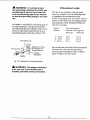
3. Most parts of your radial arm saw will be
fastened together using truss head bolts, lock-
washers, and hex nuts of the sizes shown.
(Figure 16) When different sizes are needed,
the instructions will include a sketch to help
you locate the correct size.
10

Fig. 16 - Truss Head Bolt, Lockwasher, Hex Nut
4. As you assemble your radial arm saw,
some of the holes in the parts will line up
and others will not. This happens because
some parts are used in other equipment or
for other purposes. Follow the instructions
carefully. The figures will show which holes
should line up in each step.
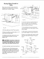
Model 113.198611
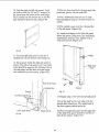
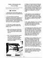
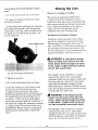
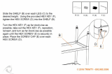
1. Turn the shelf upside down on the floor.
The wide edge should point down, and the
three narrow edges should point up.
(Figure 18)
Rear Shelf T
Stiffener _ '_
, /-___ I Under Support
Front Shelf Stiffener
Shelf
\
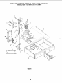
Beginning the Cabinet
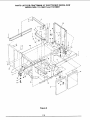
The following parts are used in the cabinet as-
sembly for model 113.198611:
A.
B.
C.
D.
E.
F.
G.
H.
I.
J.
K.
L.
Right Side Panel .................. 1
Left Side Panel ................... 1
Shelf ............................ 1
Under Support ................... 1
Skirts ............................ 2
Front Shelf Stiffener .............. 1
Corner Brackets .................. 4
Lower Support ................... 1
Rear Supports .................... 3
Upper Support ................... 1
Front Support .................... 1
Rear Shelf Stiffener ............... 1
E
\
J
I
\
H
I
/
Fig. 17 - Cabinet Ass embly - 113.198611
11
Fig. 18
Angled End Of
Lower Support
* tt /
Lower Support
2. Place the front shelf stiffener inside and
against the front edge of the shelf so that all
six holes line up. (Figure 18)
3. Place the under support on the shelf, so that
the two holes on one end line up with the
center holes on the other two parts.
(Figure 18)
4. Place the lower support under the shelf. It
should rest directly below the under support,
with the angled end sticking out. Line up the
four holes in these three pieces. (Figure 18)
Note: The angled end of the lower support is
a useful way to tell the front of the cabinet
from the back. The angled end is at the front
of the cabinet.
5. Place the rear shelf stiffener on the shelf so
that the two ends fit beween the edges of the
shelf, and the two center holes line up with
the holes at the end of the under support.
(Figure 18)

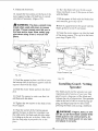
6.Put trussheadbolts through the eight
holesindicated. Put alockwasherandhexnut
on eachbolt tighten usinga7/16 inchwrench
or socket.
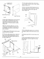
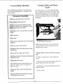
7.Put a comer bracket in each corner of the
shelf (Figure 19)
Long End Of Shelf
Long End Of Shelf
_r Bracket
Fig. 19
8. PUt two truss head bolts through the shelf
and each comer bracket to hold the brackets
in place. Only put bolts through holes in the
long edges of the shelf, not the narrow ends,
as shown. (Figure 19)
9. PUt a lockwasher and hex nut on each bolt
and hand-tighten.
Attaching Casters / Building Foot Assemblies
The following parts are used in the caster and
foot assemblies for model 113.198611:
A.
B.
C.
D.
E.
G°
H.
I.
J.
K.
L.
Casters .......................... 4
Actuator Boxes ................... 2
Levers ........................... 2
Rods ............................ 2
Retaining Plates .................. 2
Grooved Pins ..................... 2
Smooth Pins ...................... 2
Washers ......................... 2
Springs .......................... 2
Hex Nuts 3/8-16 .................. 2
Leveling Feet ..................... 2
Phillips Head Screws 10-32x3/8 ..... 4
C
Fig. 20 - Parts for Caster / Foot Assembfies
1. Put the casters" (wheels) on the shelf and
comer brackets. Since the shelf is upside
down, the wheeL_ will point up. Line up four
holes in each corner. (Figure 21)
Corner Bracket_
Shelf
Caster (Wheel)
Fig. 21
2. Put bolts through the four holes in each
corner. Put a lockwasher and hex nut on each
bolt and tighten using a 7/16 inch wrench or
socket.
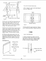
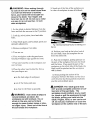
3. Separate all of the parts for the foot as-
semblies into two groups. There are two sets
12

of identical parts. These will be put together
into left and right foot assemblies which are
mirror images of each other. (Figure 22)
6. Put a groovedpin through the hole in the
rod.
7. Put a washer and spring in place on the bot-
tom of the rod, and then slide the rod all the
way down. (Figure 24)
Fig. 22 - Left and Right Foot Assemblies
4. Place an actuator box in front of you with
the C-shaped slot facing you and the closed
surface of the box to the left. This will be-
come the left foot assembly. (Figure 23)
Rod
Actuator Box
Fig. 24 - Building Left Foot Assembly
Square
Opening
Grooved Pin
"Washer And
Spring
C-Shaped
Slot
Actuator Box
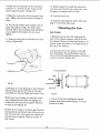
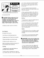
8. Slide a lever through the C-shaped slot in
the actuator box, through the square hole in
the rod, and through the square opening in
the back of the actuator box. Make sure that
the lever bends toward the left. (Figure 25)
Lever - Bends
Toward Left
Fig. 23
5. Slide a rod halfway down into the actuator
box. Make sure that the threaded end of the
rod is down, and that the smaller square open-
ing in the rod is facing you.
C-Shale
Smooth Pin
_'_ Actuator Box
Fig. 25 - Building Left Foot Assembly
13

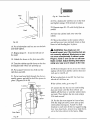
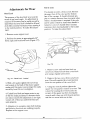
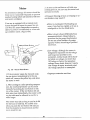
9. Apply a few drops ofoil (SAE No. 10W-30
automotive engine oil) to the lever where it
passes through the square hole in the rod.
10. Put a smooth pin through the hole in back
of the lever. (Figure 25)
11. Pull the lever forward so that the smooth
pin is in the groove on the actuator box.
12. Place a retaining plate over the smooth pin
with the smaller two holes on top.
13. Place two Phillips head screws in the top
two holes and tighten using a Phillips
screwdriver. (Figures 26 & 27)
Retaining Plate-
Small Holes On Top
J
Smooth Pin In Groove
Fig. 26
Fig. 27 - Phillips Head Screw
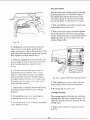
14. Put a hex nut on one of the leveling feet
and hand-tighten. (Figure 28)
Fig. 28 - Hex Nut for Leveling Foot
15. Screw the leveling foot into the rod until
the hex nut reaches the bottom of the rod.
(Figure 29)
Fig. 29 - Left Foot Assembly
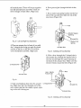
16. Place the second actuator box in front of
you with the C-shaped slot facing you and the
closed surface of the box to the right. This
will become the right foot assembly.
17. Repeat steps 5-15 to put together the
right foot assembly. The lever should bend
toward the right in the right foot assembly
(see step 8).
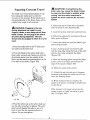
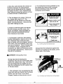
Attaching Foot Assemblies
1. Find the right and left side panels. Look
carefully to find the "R" and "L" stamped in
the metal near the center of the rear edges
(opposite the J-shaped slots). These stamps
are the easiest way to tell the right panel from
the left. (Figure 30)
Fig. 30
14

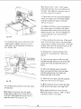
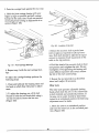
2. Lock the lever on the right foot assembly in
the down position.
3. Attach this foot assembly to the right side
panel by sticking the lever through the J-
shaped slot in the side panel, and screwing in
two slotted screws.
(Figures 31 & 32)
Right Foot Assembly
"_ J-Shaped Slot
Right Side Panel
Leveling Foot
Fig31.
Lever- Locked Down
Fig. 32 - Slotted Screws
4. Repeat steps 2-3 with the left foot assembly,
left side panel and left lever.
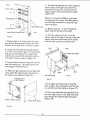
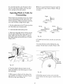
Finishing the Cabinet
1. Find the twelve outer brackets and twelve
center slides that will be put together to form
the slide brackets. (Figure 33)
2. Grease the twelve center slides on top and
bottom using the grease packets included with
your saw.
3. Slide each center slide into an outer bracket.
There are two notches on each center slide
that stick out on opposite sides. Make sure
that you insert the notch sticking out toward
the outer bracket first. This notch should stop
the center slide from sliding off the outer
bracket. (Figure 33)
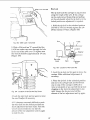
4. Hold a rear support with the long tabs
down, short tabs up, and the solid surface
facing you.
5. Attach three slide brackets to the left side
of this rear support with three truss head
bolts. Make sure that you attach the larger
hole in the slide bracket to the rear support.
Put a lockwasher and hex nut on each bolt
and tighten using a 7/16 inch wrench or sock-
et. (Figure 34)
i[_ _-----Short Tabs
tl ---Rear Support- Solid
H S°r'a e
er Hole
acke,
Long Tabs--------, _]
Center Slide Outer Bracket
/
\ / /
Stop Tab Stop Tab Rear StopStop Tab
Fig. 33
Fig. 34
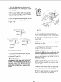
6. Attach this rear support to the right side
panel with two truss head bolts. Make sure
that the long tabs are on the bottom and the
short tabs are on top. Make sure that the
solid surface is facing front. Put a lockwasher
and hex nut on each bolt and tighten using a
7/16 inch wrench or socket. (Figure 35)
15

Rear
Short
Long Tabs
Right Side Panel
Inside Edge Of Side Panel
Front
Fig. 35
7. Repeat steps 4 - 6 with another rear sup-
port and the left side panel. Attach the slide
brackets to the right side of this rear support
8. Attach the front end of each slide bracket
to a hole on the inside edge of the sidepanels
with six truss head bolts. Put a lockwasher
and hex nut on each bolt and tighten with a
7/16 inch wrench or socket. (Figure 35)
9. Lay the shelf on the rear edge with the bot-
tom side toward you. The angled end of the
lower support should point up.
10. Place the fight sidepanel on the right side
of the shelf. The slide brackets should be on
the inside of the cabinet. (Figure 36)
Angled End Of
Support
Bottom Side Of Shelf
Right Side Panel
11. Put bolts through the four holes along the
bottom edge of the Hght side panel. Put a
lockwasher and hex nut on each bolt and
tighten using a 7/16 inch wrench or socket.
(Figure 36)
Note: It is sometimes difficult to get bolts
through these four holes. You may need to
use a Phillips screwdriver to help shift the
parts into place.
12. Repeat steps 10 - 11 with the left side
panel and the left side of the shelf.
13. Turn the cabinet so that it is on the
wheels. Attach the skirts to the top of the side
panels, with one on the front of the cabinet
and the other on the back. (Figure 37)
Rear
Side Panel
Shelf
Left Side Panel Front
Skirt
Fig. 37
14. Use eight truss head bolts to hold the
skirts in place. Put a lockwasher and hex nut
on each bolt and hand-tighten. (Figure 37)
15. Put a truss head bolt through the hole at
the back, right corner of the shelf. This hole
goes through the shelf and right side panel.
(Figure 38)
Fig. 36
16

Rear
Right Side
Panel
Shelf
Front
Fig. 38
16. Put a lockwasher and hex nut on the bolt
and hand-tighten.
17. Repeat steps 15 - 16 on the left side of
the shelf.
18. Unlock the levers on the foot assemblies.
19. Turn the cabinet upside down so that the
leveling feet and wheels are pointing up.
20. Put a spacer between the shelf and the
right foot assembly.
21. Put a truss head bolt through the foot as-
sembly, spacer, and shelf to hold the spacer in
place. (Figures 39 & 40)
1/4-20xl _-----_._ Spacer
Shelf
Fig. 39
17
Fig. 40 - Truss Head Bolt
22. Put a lockwasher and hex nut on the bolt
and tighten using a 7/16 wrench or socket.
23. Repeat steps 20 - 22 with the left foot as-
sembly.
24. Turn the cabinet back over onto the
wheels.
25. Move the cabinet to the location where
you will use your saw and push down on foot
levers to lock leveling feet in place.
_1_ WARNING: Saw blade can roll
forward toward you if the leveling feet are
not correctly adjusted. Workpiece or saw
can move unexpectedly if cabinet rocks.
Fingers, hand or arm can be cut off from
blade contact. Adjust leveling feet before
using your saw so arm slopes to the rear.
26. If the leveling feet lift the front two wheels
slightly off the floor and the cabinet does not
rock, go to step 28, or
If the leveling feet do not lift the front two
wheels off the floor, or
If the cabinet rocks, go to step 27.
27. Loosen the the hex nut on each leveling
foot and rotate until the front wheels are
slightly off the floor or until the cabinet does
not rock. Then tighten the hex nuts using a
9/16 inch wrench.
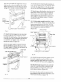
28. Put the last rear support in front of you
with the long tabs down, short tabs up and
solid surface facing you. Attach two slide
brackets to each side of this rear support using
four truss head bolts. Attach these slide brack-
ets to the holes shown in the figure. Make

surethat you attachthe largerhole in each
slide bracket to the rear support. Put a lock-
washer and hex nut on each bolt and tighten
using a 7/16 wrench or socket. (Figure 41)
Slide Bracket Short
Front
Support -
Solid Surface
Fig. 41
er Hole
S L!ler
; Hole
i,l Long Tabs
\L Rear Support - Solid Surface
29. Attach the front support to the four slide
brackets using four truss head bolts. Make
sure that the solid surface of the front support
is facing front. Put a lockwasher and hex nut
on each bolt and tighten with a 7/16 inch
wrench or socket. (Figure 41)
30. Put the upper support in place between
the rear and front supports. Make sure that
the upper support is inside the surfaces of the
other two parts. (Figure 42)
Larger Ho_e
Last Two Slide Brackets
Smaller-
Hole
Upper Support
Support
Rear Support
Fig. 42
31. Put the last two slide brackets in place on
each side of the front and rear supports. Make
sure that the larger holes in the slide brackets
are in line with the rear support. (Figure 42)
32. Attach these sfide brackets using four truss
head bolts. These bolts will go through the
slide bracket, rear or front support, and the
upper support. Put a lockwasher and hex nut
on each bolt and tighten using a 7/16 inch
wrench or socket.
33. Tilt this whole assembly and slide it into
place on the cabinet. Make sure that the front
support extends between the front s/drt and
the angled end of the lower support, and that
the rear support is inside the cabinet.
(Figure 43)
Upper Support
\
Front Skirt
Left Side Panel
I
Rear Skirt
/
/
Front
Support
Angled End Of Lower Support
I
Fig. 43
"Rear Support
34. Attach the upper and front supports to the
front skirt using two truss head bolts, lock-
washers, and hex nuts. Make sure the heads
of the bolts point down as shown. (Figure 43)
35. Attach the upper support to the rear skirt
using two truss head bolts, lockavashers and
hex nuts. Make sure the heads of the bolts
point down as shown. (Figure 43)
36. Attach the front and rear supports to the
lower support using four truss head bolts, lock-
washers, and hex nuts. (Figure 43)
18

37. Tighten all screws, except those on the
front and rear skirts, using a 7/16 inch wrench
or socket.
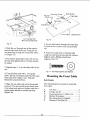
Putting Drawers Together
The following parts are used to assemble the
drawers in model 113.198611:
A.
B.
C.
D.
E.
F.
G.
H.
I.
J.
10 inch Drawers .................. 2
6 inch Drawers ................... 2
3 inch Drawers ................... 2
10 inch Drawer Fronts ............. 2
6 inch Drawer Fronts .............. 2
3 inch Drawer Fronts .............. 2
Center Slide Brackets ............ 12
Stand Slide Brackets ............. 12
Grease Packets ................... 2
_Drawer Fastener .................... 48
Note: The center slide brackets and stand
slide brackets have already been put together
in the Finishing the Cabinet section.
D,E,F I
Fig. 44 - Parts for Drawer Assembly
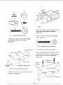
1. Find the six metal drawers and plastic
drawer fronts.
2. Slide the drawer fronts onto the drawers.
Make sure that the tabs on the plastic drawer
fronts slide over the metal drawers to help
hold them in place. (Figure 45)
Tab
Drawer Front
Drawer
Fig. 45
3. Push a plastic drawer fastener into each of
the holes to hold the drawers together.
(Figure 45)
4. Put the drawers aside. Do not put the
drawers into the cabinet until after you mount
the saw.
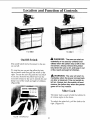
Model 113.198411
Building the Cabinet
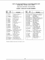
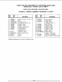
1. The following parts are used in the cabinet
assembly for model 113.198411:
A°
B.
C.
D.
E.
F.
G.
H.
I.
J.
K.
L.
M
Right Side Panel .................. 1
Left Side Panel ................... 1
Shelf ............................ 1
Under Support ................... 1
Skirts ............................ 2
Front Shelf Stiffener .............. 1
Corner Brackets .................. 4
Lower Support ................... 1
Spacers .......................... 2
Upper Support ................... 1
Front Support .................... 1
Doors ........................... 2
Rear Shelf Stiffener ............... 1
19

I G
G
F
Fig. 46 - Cabinet Assembly - 113.198411
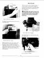
1. Turn the shelf upside down on the floor.
The wide edge should point down, and the
three narrow edges should point up.
(Figure 47)
Fig. 47
8
Lower Support
Angled End Of
Lower Support
2. Place the front shelf stiffener inside and
against the front edge of the shelf so that all
six holes line up. (Figure 47)
3. Place the under support on the shelf so that
the two holes on one end line up with the
center holes on the other two parts.
(Figure 47)
2O
4. Place the lower support under the shelf. It
should rest directly below the under support,
with the angled end sticking out. Line up the
four holes in these three pieces. (Figure 47)
Note: The angled end of the lower support is
a useful way to tell the front of the cabinet
from the back. The angled end is at the front
of the cabinet.
5. Place the rear shelf stiffener on the shelf so
that the two ends fit beween the edges of the
shelf, and the two center holes line up with
the holes at the end of the under support.
(Figure 47)
6. Put truss head bolts through the eight
holes indicated. Put a lockwasher and hex nut
on each bolt and tighten using a 7/16 inch
wrench or socket..
7. PUt a comer bracket in each corner of the
shelf. (Figure 48)
Long End Of Shelf
Long End Of Shelf
o
Corner Bracket
Fig. 48
8. Put two truss head bolts through the shelf
and each comer bracket to hold the brackets
in place. Only put bolts through holes in the
long edges of the shelf, not the narrow ends,
as shown. (Figure 48)
9. Put a lockwasher and hex nut on each bolt
and tighten using a 7/16 inch wrench or
socket.
Page is loading ...
Page is loading ...
Page is loading ...
Page is loading ...
Page is loading ...
Page is loading ...
Page is loading ...
Page is loading ...
Page is loading ...
Page is loading ...
Page is loading ...
Page is loading ...
Page is loading ...
Page is loading ...
Page is loading ...
Page is loading ...
Page is loading ...
Page is loading ...
Page is loading ...
Page is loading ...
Page is loading ...
Page is loading ...
Page is loading ...
Page is loading ...
Page is loading ...
Page is loading ...
Page is loading ...
Page is loading ...
Page is loading ...
Page is loading ...
Page is loading ...
Page is loading ...
Page is loading ...
Page is loading ...
Page is loading ...
Page is loading ...
Page is loading ...
Page is loading ...
Page is loading ...
Page is loading ...
Page is loading ...
Page is loading ...
Page is loading ...
Page is loading ...
Page is loading ...
Page is loading ...
Page is loading ...
Page is loading ...
Page is loading ...
Page is loading ...
Page is loading ...
Page is loading ...
Page is loading ...
Page is loading ...
Page is loading ...
Page is loading ...
Page is loading ...
Page is loading ...
Page is loading ...
Page is loading ...
Page is loading ...
Page is loading ...
Page is loading ...
Page is loading ...
Page is loading ...
Page is loading ...
Page is loading ...
Page is loading ...
Page is loading ...
Page is loading ...
Page is loading ...
Page is loading ...
Page is loading ...
Page is loading ...
Page is loading ...
Page is loading ...
Page is loading ...
Page is loading ...
Page is loading ...
Page is loading ...
Page is loading ...
Page is loading ...
Page is loading ...
Page is loading ...
Page is loading ...
Page is loading ...
Page is loading ...
Page is loading ...
Page is loading ...
Page is loading ...
Page is loading ...
Page is loading ...
Page is loading ...
Page is loading ...
Page is loading ...
Page is loading ...
Page is loading ...
Page is loading ...
Page is loading ...
Page is loading ...
-
 1
1
-
 2
2
-
 3
3
-
 4
4
-
 5
5
-
 6
6
-
 7
7
-
 8
8
-
 9
9
-
 10
10
-
 11
11
-
 12
12
-
 13
13
-
 14
14
-
 15
15
-
 16
16
-
 17
17
-
 18
18
-
 19
19
-
 20
20
-
 21
21
-
 22
22
-
 23
23
-
 24
24
-
 25
25
-
 26
26
-
 27
27
-
 28
28
-
 29
29
-
 30
30
-
 31
31
-
 32
32
-
 33
33
-
 34
34
-
 35
35
-
 36
36
-
 37
37
-
 38
38
-
 39
39
-
 40
40
-
 41
41
-
 42
42
-
 43
43
-
 44
44
-
 45
45
-
 46
46
-
 47
47
-
 48
48
-
 49
49
-
 50
50
-
 51
51
-
 52
52
-
 53
53
-
 54
54
-
 55
55
-
 56
56
-
 57
57
-
 58
58
-
 59
59
-
 60
60
-
 61
61
-
 62
62
-
 63
63
-
 64
64
-
 65
65
-
 66
66
-
 67
67
-
 68
68
-
 69
69
-
 70
70
-
 71
71
-
 72
72
-
 73
73
-
 74
74
-
 75
75
-
 76
76
-
 77
77
-
 78
78
-
 79
79
-
 80
80
-
 81
81
-
 82
82
-
 83
83
-
 84
84
-
 85
85
-
 86
86
-
 87
87
-
 88
88
-
 89
89
-
 90
90
-
 91
91
-
 92
92
-
 93
93
-
 94
94
-
 95
95
-
 96
96
-
 97
97
-
 98
98
-
 99
99
-
 100
100
-
 101
101
-
 102
102
-
 103
103
-
 104
104
-
 105
105
-
 106
106
-
 107
107
-
 108
108
-
 109
109
-
 110
110
-
 111
111
-
 112
112
-
 113
113
-
 114
114
-
 115
115
-
 116
116
-
 117
117
-
 118
118
-
 119
119
-
 120
120


Craftsman 113198611 Owner's manual
- Type
- Owner's manual
- This manual is also suitable for
Ask a question and I''ll find the answer in the document
Finding information in a document is now easier with AI
Related papers
-
Craftsman 113234610 Owner's manual
-
-
-
-
-
-
-
-
-
Other documents
-
Makita 2704 User manual
-
-
Pure Garden M150028 Operating instructions
-
Chicago Electric 61973 Quick start guide
-
 TRINITY XBS-03-012-4417 User manual
-
JASIWAY J-S2016N-WT User manual
-
Thule 102 User manual
-
 POWER SOCCER SHOP PN 1525 User manual
-
Midmark 6271 - 6276 (Wall Mounted Units) Installation guide
-
 EZ Slide Cabinet Hardware 092 Installation guide


