Maytag MIM1554WRS0 Owner's manual

Type
Owner's manual

This manual is also suitable for

THANK YOU for purchasing this high-quality product. If you should experience a problem not covered in TROUBLESHOOTING,
please visit our website at www.maytag.com for additional information. If you still need assistance, call us at 1-800-688-9900.
In Canada, visit our website at www.maytag.ca or call us at 1-800-807-6777.
You will need your model and serial number, located on the inside wall of the ice maker compartment.
Para obtener acceso a "lnstrucciones para el usuario de lafabrica de hielo" en espa_ol, o para obtener informaci6n adicional
acerca de su producto, visite: www.maytag.com.
Necesitara su nQmerode modelo y de serie, ubicado en el interior del compartimiento de la fabrica de hielo.
Table of Contents / Table des rnati_res
ICE MAKER SAFETY ................................................................ 1
INSTALLATION INSTRUCTIONS ............................................. 2
ICE MAKER USE ....................................................................... 7
ICE MAKER CARE .................................................................... 8
TROUBLESHOOTING ............................................................. 11
WAR RANTY ............................................................................. 13
SECURITE DE LA MACHINE A GLAgONS ........................... 14
INSTRUCTIONS D'INSTALLATION ....................................... 15
UTILISATION DE LA MACHINE A GLAQONS ...................... 21
ENTRETIEN DE LA MACHINE A GLAQONS ........................ 22
DI:!:PANNAGE ........................................................................... 25
GARANTIE ............................................................................... 27
ICE MAKER SAFETY
Your safety and the safety of others are very important.
We have provided many important safety messages in this manual and on your appliance. Always read and obey all safety
messages.
This is the safety alert symbol.
This symbol alerts you to potential hazards that can kill or hurt you and others.
All safety messages will follow the safety alert symbol and either the word "DANGER" or "WARNING."
These words mean:
You can be killed or seriously injured if you don't immediately
follow instructions.
You can be killed or seriously injured if you don't follow
instructions.
All safety messages willtell you what the potential hazard is, tell you how to reduce the chance of injury, and tell you what can
happen if the instructions are not followed.
W10206488B
IMPORTANT SAFETY INSTRUCTIONS
WARNING: To reduce the risk of fire, electric shock, or injury when using your ice maker, follow these basic
precautions:
Plug into a grounded 3 prong outlet.
Do not remove ground prong.
Do not use an adapter.
Do not use an extension cord.
Disconnect power before cleaning.
Disconnect power before servicing.
Replace all parts and panels before operating.
Use two or more people to move and install ice maker.
SAVE THESE INSTRUCTIONS
INSTALLATION INSTRUCTIONS
Excessive Weight Hazard !
m
Use two or more people to move and install ice maker.
|
Failure to do so can result in back or other injury.
Removing Packaging Materials
Remove tape and glue from your ice maker before using.
To remove any remaining tape or glue from the exterior of the
ice maker, rub the area briskly with your thumb. Tape or glue
residue can also be easily removed by rubbing a small
amount of liquid dish soap over the adhesive with your
fingers. Wipe with warm water and dry.
Do not use sharp instruments, rubbing alcohol, flammable
fluids, or abrasive cleaners to remove tape or glue. Do not
use chlorine bleach on the stainless steel surfaces of the ice
maker. These products can damage the surface of your ice
maker.
Cleaning Before Use
After you remove all of the packaging materials, clean the inside
of your ice maker before using it. See the cleaning instructions in
the "Ice Maker Care" section.
To ensure proper ventilation for your ice maker, the front side
must be completely unobstructed. The ice maker may be
closed-in on the top and three sides, but the installation
should allow the ice maker to be pulled forward for servicing
if necessary.
Installation of the ice maker requires acold water supply inlet
of 1/4"(6.35 mm) OD soft copper tubing with a shutoff valve
and either a gravity-drain system or condensate pump to
carry the water to an existing drain.
Choose a well ventilated area with temperatures above 55°F
(13°C) and below 110°F (43°C). Best results are obtained
between 70°F (21°C) and 90°F (32°C).
This unit must be installed in an area sheltered from the
elements, such as wind, rain, water spray, or drip.
When installing the ice maker under a counter, follow the
recommended opening dimensions shown. Place electrical
and plumbing fixtures in the recommended location as
shown.
NOTES:
Be sure the power supply cord is not pinched between
the ice maker and the cabinet.
Be sure the water supply line is not pinched between the
ice maker and the cabinet.
Be sure the drain line (on some models) is not pinched
between the ice maker and the cabinet.
34 II
(86.4 cm)
Min.
341/2''
(87.6 cm)
Max.
cm)
1 4
I ,I
(38.1 cm)
A.Recommended location for electrical
and plumbing fixtures
B.Floor level
A
B
Choose a location where the floor is even. It is important for
the ice maker to be level in order to work properly. If needed,
you can adjust the height of the ice maker by changing the
height of the leveling legs. See "Leveling."
2
.......
Electrical Shock Hazard
Plug into a grounded 3 prong outlet.
Do not remove ground prong.
Do not use an adapter.
Do not use an extension cord.
Failure to follow these instructions can result in death,
fire, or electrical shock.
Before you move your ice maker into its final location, it is
important to make sure you have the proper electrical
connection:
A 115 Volt, 60 Hz., AC only, 15- or 20-amp electrical supply,
properly grounded in accordance with the National Electrical
Code and local codes and ordinances, is required.
It is recommended that a separate circuit, serving only your ice
maker, be provided. Use a receptacle which cannot be turned off
by a switch or pull chain.
IMPORTANT: If this product is connected to a GFCI (Ground
Fault Circuit Interrupter) equipped outlet, nuisance tripping of the
power supply may occur, resulting in loss of cooling. Ice quality
may be affected. If nuisance tripping has occurred, and if the
condition of the ice appears poor, dispose of it.
Recommended grounding method
This appliance must be grounded. This appliance is equipped
with a power supply cord having a 3 prong grounding plug. The
cord must be plugged into a mating, 3 prong, grounding-type
wall receptacle, grounded in accordance with the National
Electrical Code and local codes and ordinances. If a mating wall
receptacle is not available, it is the personal responsibility of the
customer to have a properly grounded, 3 prong wall receptacle
installed by a qualified electrician.
A cold water supply with water pressure of between 30 and
120 psi (207 and 827 kPa) is required to operate the ice maker. If
you have questions about your water pressure, call a licensed,
qualified plumber.
Reverse Osmosis Water Supply
IM PORTANT:
Reverse osmosis water filtration systems can be used only
with ice maker installations that have a gravity drain. A
reverse osmosis system is not recommended for ice makers
that have a drain pump installed.
The pressure of the water supply coming out of a reverse
osmosis system going to the water inlet valve of the ice
maker needs to be between 30 and 120 psi (207 and
827 kPa).
If a reverse osmosis water filtration system is connected to your
cold water supply, the water pressure to the reverse osmosis
system needs to be a minimum of 40 to 60 psi (276 to 414 kPa).
NOTE: The reverse osmosis system must provide 1 gal. (3.8 L) of
water per hour to the ice maker for proper ice maker operation. If
a reverse osmosis system is desired, only a whole-house
capacity reverse osmosis system, capable of maintaining the
steady water supply required by the ice maker, is recommended.
Faucet capacity reverse osmosis systems are not able to
maintain the steady water supply required by the ice maker.
If the water pressure to the reverse osmosis system is less than
40 to 60 psi (276 to 414 kPa):
Check to see whether the sediment filter in the reverse
osmosis system is blocked. Replace the filter if necessary.
Allow the storage tank on the reverse osmosis system to refill
after heavy usage.
If you have questions about your water pressure, call a licensed,
qualified plumber.
It is important for the ice maker to be level in order to work
properly. Depending upon where you install the ice maker, you
may need to make several adjustments to level it. You may also
use the leveling legs to lower the height of the ice maker for
undercounter installations.
Tools needed:
Gather the required tools and parts before starting installation.
9" level
Adjustable wrench
NOTE: It is easier to adjust the leveling legs if you have another
person to assist you.
1. Move the ice maker to its final location.
NOTE: If this is a built-in installation, move the ice maker as
close as possible to the final location.
2. Place the level on top of the product to see if the ice maker is
level from front to back and side to side.
3. Push up on the top front of the ice maker, and then locate the
leveling screws that are on the bottom front of the ice maker.
4. Using an adjustable wrench, change the height of the legs as
follows:
Turn the leveling leg to the right to lower that side of the
ice maker.
Turn the leveling leg to the left to raise that side of the ice
maker.
NOTE: The ice maker should not wobble. Use shims to add
stability when needed.
5. Push up on the top rear of the ice maker and locate the
leveling legs that are on the bottom rear of the ice maker.
6. Follow the instructions in Step 4 to change the height of the
legs.
7. Use the level to recheck the ice maker to see that it is even
from front to back and side to side. If the ice maker is not
level, repeat steps 2 to 5. If the ice maker is level, go to the
"Connect Water Supply" section.
Readalldirectionsbeforeyoubegin.
IMPORTANT:
Plumbingshallbeinstalledinaccordancewiththe
InternationalPlumbingCodeandanylocalcodesand
ordinances.
UsecoppertubingorWhirlpoolsupplyline,PartNumber
8212547RP,andcheckforleaks.
Installtubingonlyinareaswheretemperatureswillremain
abovefreezing.
Toolsneeded:
Gathertherequiredtoolsandpartsbeforestartinginstallation.
Flat-bladescrewdriver
7/le"and1/2"open-endwrenchesortwoadjustablewrenches
1/4"nutdriver
NOTE:Donotuseapiercing-typeor3Ae"(4.76mm)saddlevalve
whichreduceswaterflowandclogsmoreeasily.
ConnectingtheWaterLine
1.
2.
Turn off main water supply. Turn on nearest faucet long
enough to clear line of water.
Using a 1/2"copper supply line with a quarter-turn shutoff
valve or the equivalent, connect the ice maker as shown.
NOTE: To allow sufficient water flow to the ice maker a
minimum 1/2"size copper supply line is recommended.
A
I/ II
B
3,
A. Bulb
B. Nut
Now you are ready to connect the copper tubing. Use 1/4"
(6.35 mm) OD soft copper tubing for the cold water supply.
Ensure that you have the proper length needed for the
job. Be sure both ends of the copper tubing are cut
square.
Slip compression sleeve and compression nut on copper
tubing as shown. Insert end of tubing into outlet end
squarely as far as it will go. Screw compression nut onto
outlet end with adjustable wrench. Do not overtighten.
A. Compression sleeve
B. Compression nut
C. Copper tubing
D. Coupfing (purchased)
4. Place the free end of the tubing into a container or sink, and
turn on main water supply and flush out tubing until water is
clear. Turn off shutoff valve on the water pipe.
NOTE: Always drain the water line before making the final
connection to the inlet of the water valve to avoid possible
water valve malfunction.
5. Bend the copper tubing to meet the water line inlet which is
located on the back of the ice maker cabinet as shown.
Leave a coil of copper tubing to allow the ice maker to be
pulled out of the cabinet or away from the wall for service.
REAR VIEW
B
C
D
A. Water supply tube clamp
B. Vent hose (drain pump models only)
C. Water supply line
D. Inlet water tube clamp
E. Drain hose (drain pump models only)
6,
7.
Remove and discard the short, black plastic tube from the
end of the water line inlet.
Thread the nut onto the coupling on the end of the tubing.
Tighten the nut by hand. Then tighten it with a wrench two
more turns. Do not overtighten.
NOTE: To avoid rattling, be sure the copper tubing does not
touch the cabinet's side wall or other parts inside the cabinet.
A B C D E F G
A. Line to ice maker
B. Nut (purchased)
C. Ferrule (purchased)
D. Coupfing (purchased)
E. Ferrule
F Nut
G. Supplied line from
ice maker
8. Install the water supply tube clamp around the water supply
line to reduce strain on the coupling.
9. Turn shutoff valve ON.
10. Check for leaks. Tighten any connections (including
connections at the valve) or nuts that leak.
Gravity Drain System
Connect the ice maker drain to your drain in accordance with all
state and local codes and ordinances. If the ice maker is
provided with a gravity drain system, follow these guidelines
when installing drain lines. This will help keep water from flowing
back into the ice maker storage bin and potentially flowing onto
the floor causing water damage.
Drain lines must have a minimum of 5/8"(15.88 mm) inside
diameter.
Drain lines must have a 1" drop per 48" (2.54 cm drop per
122 cm) of run or V4"drop per 12" (6.35 mm per 30.48 cm) of
run and must not have low points where water can settle.
The floor drains must be large enough to accommodate
drainage from all drains.
The ideal installation has a standpipe with a 1W' (3.81 cm) to
2" (5.08 cm) PVC drain reducer installed directly below the
outlet of the drain tube as shown. You must maintain a
1" (2.54 cm) air gap between the drain hose and the
standpipe.
It may be desirable to insulate the drain line thoroughly up to
the drain inlet.
SIDE VIEW
I
I
T
(4.8 cm)
23 II
(58.4 cm)
2-.11/2 ''
(5 cm - 3.8 cm)
(2.54 cm)
C
D
A. Drain hose
B. 1" (2.54 cm) air gap
C. PVC drain reducer
D. Center of drain should be 23" (58.4 cm) from front of door,
with or without the 3/4"(1.91 cm) panel on the door. The
drain should also be centered from left to right (7_"
[18.56 cm] from either side of the ice maker).
Drain Pump System (on some models)
Connect the ice maker drain to your drain in accordance with the
International Plumbing Code and any local codes and
ordinances.
NOTE: If the drain hose becomes twisted and water cannot
drain, your ice maker will not work.
Connecting the Drain
After ensuring that the drain system is adequate, follow these
steps to properly place the ice maker:
Electrical Shock Hazard
Plug into a grounded 3 prong outlet.
Do not remove ground prong.
Do not use an adapter.
Do not use an extension cord.
Failure to follow these instructions can result in death,
fire, or electrical shock.
1. Plug into a grounded 3 prong outlet.
Excessive Weight Hazard
Use two or more people to move and install ice maker.
Failure to do so can result in back or other injury.
2. Style 1 - For gravity drain system, push the ice maker into
position so that the ice maker drain tube is positioned over
the PVC drain reducer. See "Gravity Drain System" earlier in
this section. Style 2 - For drain pump system connect the
drain pump outlet hose to the drain. See "Drain Pump
System" earlier in this section.
3. Recheck the ice maker to be sure that it is level. See
"Leveling."
4. If it is required by your local sanitation code, seal the cabinet
to the floor with an approved caulking compound after all
water and electrical connections have been made.
Tools needed:
Gather the required tools and parts before starting installation.
5/16"wrench Flat putty knife
1/4"wrench Phillips screwdriver
Hinge pin 5_6" Hex-head hinge screw
Handlescrew
End Cap screw
Remove door
1. Unplug ice maker or disconnect power.
2. Remove the handle screws and handle (on some models).
Keep the parts together and set them aside.
3. Remove the hinge pin from the top hinge.
4. Remove the door from the hinges and screw the top hinge pin
back into the top hinge.
5. Reverse the door end caps as follows:
Remove the screw and end cap from the top corner.
Move it diagonally to the opposite side's bottom corner,
keeping the straight side of the end cap facing the front of
the ice maker.
Remove the screw and end cap from the bottom corner.
Move it diagonally to the opposite side's top corner,
keeping the straight side of the end cap facing the front of
the ice maker.
A B
D C
C
B
0
D
A
Reverse Hinges
1. Unscrew and remove the top hinge. Replace the screws in
the empty hinge holes.
2. Remove the screws from the bottom of the opposite side of
the ice maker cabinet. Turn the top hinge upside down so
that the hinge pin points up. Place the hinge on the bottom
opposite side of the ice maker and tighten screws.
3. Remove the plastic hinge pin sleeve from the "old" bottom
hinge and replace it on the new bottom hinge pin.
4. Remove the "old" bottom hinge screws and hinge. Replace
the screws in the empty hinge holes.
5. Remove the screws from the top of the opposite side of the
ice maker cabinet. Turn the hinge upside down so that the
hinge pin points down. Place the hinge on the top opposite
side of the ice maker and tighten the screws.
6. Remove the top hinge pin.
Replace Door
1. Place plastic hinge pin sleeve in the top hinge hole on the
door. Align the door with the top hinge hole and replace the
top hinge pin.
2. Replace the handle and handle screws.
Top Hinge
A
I
B
C
D
A.Hinge pin
B.Hinge pin sleeve
C.Hinge
D.Hex-head hinge screw
Bottom Hinge
A. Top corner open (no end cap)
B.Beginning top corner end cap
C. Beginning bottom corner end cap
D. Bottom corner open (no end cap)
6. Set the door aside.
J
A. Hex-head hinge screw
B. Hinge pin sleeve
C. Hinge
D. Hinge pin
D
6
Reverse Door Catch
1. Remove the hole plugs from the opposite side of the door
and set aside.
2. Remove the screws from the magnetic door catch and
replace it on the opposite side of the door.
0
3. Push the hole plugs into place on the opposite side of the
door.
Electrical Shock Hazard
Plug into a grounded 3 prong outlet.
Do not remove ground prong.
Do not use an adapter.
Do not use an extension cord.
Failure to follow these instructions can result in death,
fire, or electrical shock.
4. Plug into a grounded 3 prong outlet.
Your new ice maker may make sounds that are not familiar to
you. Because the sounds are new to you, you might be
concerned about them. Most of the new sounds are normal. Hard
surfaces such as floors, walls and cabinets can make the sounds
seem louder than they actually are. The following describes the
kinds of sounds that might be new to you and what may be
making them.
You will hear a buzzing sound when the water valve opens to
fill the water reservoir for each cycle.
Rattling noises may come from the flow of the refrigerant or
the water line. Items stored on top of the ice maker can also
make noises.
The high-efficiency compressor may make a pulsating or high
pitched sound.
Water running over the evaporator plate may make a
splashing sound.
Water running from the evaporator plate to the water reservoir
may make a splashing sound.
As each cycle ends, you may hear a gurgling sound due to
the refrigerant flowing in your ice maker.
You may hear air being forced over the condenser by the
condenser fan.
During the harvest cycle, you may hear a "thud" when the ice
sheet slides from the evaporator onto the cutter grid.
When you first start the ice maker, you may hear water
running continuously. The ice maker is programmed to run a
rinse cycle before it begins to make ice.
ICE MAKER USE
When you first start your ice maker, the water pan will fill and the
system will rinse itself before starting to make ice. The rinsing
process takes about 5 minutes.
Under normal operating conditions, the ice maker will cycle at
preset temperatures. The ice level sensor located in the ice
storage bin will monitor the ice levels.
IMPORTANT:
If the water supply to the ice maker is turned off, be sure to
set the ice maker control to OFF.
The ice maker is designed to make clear ice from the majority
of water sources on a daily basis. If your results are
unsatisfactory, your water may need to be filtered or treated.
The Ice Making Process
1.
2.
Water is constantly circulated over a freezing plate. As the
water freezes into ice, the minerals in the water are rejected.
This produces asheet of ice with a low mineral content.
When the desired thickness is reached, the ice sheet is
released and slides onto a cutter grid. The grid divides the
sheet into individual cubes.
3. Thewatercontainingtherejectedmineralsisdrainedafter
eachfreezingcycle.
4. Freshwaterentersthemachineforthenexticemakingcycle.
5. Cubesfallintothestoragebin.Whenthebinisfull,theice
makershutsoffautomaticallyandrestartswhenmoreiceis
needed.Theicebinisnotrefrigerated,andsomemeltingwill
occur.Theamountofmeltingvarieswithroomtemperature.
NOTE:Astheroomandwatertemperaturesvary,sowillthe
amountoficeproducedandstored.Thismeansthathigher
operatingtemperaturesresultinreducediceproduction.
1. Tostartthenormalicemakingcycle,selectON.
2. Tostopicemakeroperation,selectOFE
@ @ @ @
NOTES:
Pressing the ON/OFF switch does not shut off power to
the ice maker.
Allow 24 hours to produce the first batch of ice. Discard
the first batch produced.
Lock Mode
The control panel can be turned off for easy cleaning or to avoid
unintentional activation by small children or pets.
NOTE: The lock feature does not shut off power to the ice maker
or to the ice maker bin light. It simply deactivates the control
panel.
1. To lock the control panel, press and hold the LOCK button
until the indicator appears.
2. To unlock the control panel, press and hold the LOCK button
until the indicator disappears.
Service Light
The service light indicates when service is needed. If the service
light turns on, turn the ice maker off and back on. If the service
light turns on again, call for service.
Cleaning Needed Status Light
The Cleaning Needed Status light will help you know when it is
time to clean your ice maker. The light will change to yellow. This
tells you it is almost time to clean your ice maker. It is
recommended that you clean the ice maker when the status light
changes to red OR ice production decreases significantly. To
clean your ice maker, see "Ice Maker System" in the "Cleaning"
section.
ICE MAKER CARE
The ice making system and the air cooled condenser need to be
cleaned regularly for the ice maker to operate at peak efficiency
and to avoid premature failure of system components. See the
"Ice Maker System" and the "Condenser" sections.
Exterior Surfaces
Wash the exterior enamel surfaces and gaskets with warm water
and mild soap or detergent. Wipe and dry. Regular use of a good
household appliance cleaner and wax will help maintain the
finish. Do not use abrasive cleaners on enamel surfaces as they
may scratch the finish.
For products with a stainless steel exterior, use a clean sponge or
soft cloth and a mild detergent in warm water. Do not use
abrasive or harsh cleaners. Do not use chlorine bleach on
stainless steel surfaces.
Ice Maker System
Minerals that are removed from water during the freezing cycle
will eventually form a hard scaly deposit in the water system.
Cleaning the system regularly helps remove the mineral scale
buildup. How often you need to clean the system depends upon
how hard your water is. With hard water of 15 to 20 grains/gal.
(4 to 5 grains/liter), you may need to clean the system as often as
every 6 months.
NOTE: Use one 16 oz (473 mL) bottle of approved ice maker
cleaner. To order, call 1-800-442-9991 and ask for Part Number
4396808. In Canada, call 1-800-807-6777.
1. Turn off the ice maker.
2. Wait 5 to 10 minutes for the ice to fall into the storage bin.
Remove all ice from the storage bin.
3. Unscrew the drain cap from the bottom of the water pan
located inside the storage bin as shown. Allow the water to
drain completely.
4. Replace the drain cap securely on the water pan. If the drain
cap is loose, water will empty from the water pan and you will
have either thin ice or no ice.
5. Read and follow all handling information on the cleaner bottle
before completing the steps below. Use one 16 oz (473 mL)
bottle of approved ice maker cleaner.
6. Pour one bottle of solution into the water pan. Fill the bottle
twice with tap water and pour it into the water pan.
B--
.,-\\ ..j/
| ,JL,_
' ,, C
A. Water pan
B. Water pan thumb screws
C. Drain cap
8
7. Press and hold the CLEAN button. See "Using the Controls."
The light will blink, indicating that the cleaning cycle is in
process. When the indicator light turns green (approximately
70 minutes), the cleaning cycle is complete. During the
cleaning cycle, the system will both clean and rinse itself.
8. After the cleaning cycle is complete, remove the drain cap
from the water pan. Look for any cleaning solution left in the
water pan. If cleaning solution drains from the water pan, you
should run the clean cycle again. Be sure to replace the drain
cap securely on the water pan. If the drain cap is loose, water
will empty from the water pan and you will have either thin ice
or no ice.
NOTE: Severe scale buildup may require repeated cleaning with
a fresh quantity of cleaning solution.
9. Press the ON button to resume ice production.
Condenser
A dirty or clogged condenser:
Obstructs proper airflow.
Reduces ice making capacity.
Causes higher than recommended operating temperatures
which may lead to component failure.
E(ectrica( Shock Hazard
Disconnect power before cleaning.
Replace all parts and panels before operating.
Failure to do so can result in death or electrical shock.
1. Unplug ice maker or disconnect power.
2. Remove the two screws in the lower access panel and the
two screws from the base grille area of the front panel
support.
3. Pull the bottom forward and then pull down to remove the
lower access panel.
4. Remove dirt and lint from the condenser fins and the unit
compartment with a brush attachment on a vacuum cleaner.
5. Replace the lower access panel using the four screws.
6. Plug in ice maker or reconnect power.
Interior Components
1. Unplug ice maker or disconnect power.
2. Open the storage bin door and remove any ice that is in the
bin.
3. Remove the drain cap from the water pan and drain
thoroughly. Replace the drain cap securely on the water pan.
If the drain cap is loose, water will empty from the water pan,
and you will have either thin ice or no ice.
4. Remove the two screws that hold the cutter grid cover in
place and remove the cutter grid cover.
5. Unplug the wiring harness from the left side of the cutter grid.
A. Cutter grid cover
B. Screws
6. Unplug the ice level sensor from the right side of the cutter
grid. Pull the ice level sensor down and forward away from
the cutter grid.
7. Remove the right-hand and left-hand screws. Lift the cutter
grid up and out.
NOTE: Make sure the plastic spacer from the right-hand side
of the cutter grid bracket stays with the cutter grid.
8=
Ag_ ........... _ ........................... EO
A. Cutter grid harness
B. Screw
C. Cutter grid
D. Ice level sensor harness
E. Plastic spacer
F. Screw
Remove the two thumb screws that hold the water pan in
place. Push down with one hand on the front of the pan while
pulling forward on the bottom back side.
B--
[ -I\\ -1o \ -j
_L_ ......................A
................B
J_'"(_ ...........C
A. Waterpan
B. Water pan thumb screws
C. Drain cap
9.
Remove, clean and replace the ice scoop and ice scoop
holder.
After removing the ice scoop, remove the holder by
removing the two thumb screws.
Wash the ice scoop holder along with the other interior
components using the following instructions.
Replace the ice scoop holder by replacing the thumb
screws.
A '<::::iii_iiiiiiiii
A. Thumb screws
B. Ice scoop holder
10. Wash the interior components (cutter grid, exterior of hoses,
and water pan) and the storage bin, door gasket, ice scoop,
and ice scoop holder with mild soap or detergent and warm
water. Rinse in clean water. Then clean the same parts with a
solution of 1 tbs (15 mL) of household bleach in 1 gal. (3.8 L)
warm water. Rinse again thoroughly in clean water.
NOTE: Do not remove hoses. Do not wash plastic parts in
dishwasher. They cannot withstand temperatures above
145°F (63°C).
11. Replace water pan by pushing back on the bottom with one
hand while pushing up and back on the top. Secure the water
pan by replacing both screws.
12. Check the following:
Drain cap from the water pan is securely in place. If the
drain cap is loose, water will empty from the water pan,
and you will have either thin ice or no ice.
Hose from water pan is inserted into storage bin drain
opening.
13. Slide the cutter grid back into place and secure it by
replacing the right-hand screw and plastic spacer. Then
tighten the left-hand screw. Reconnect the cutter grid
harness and the ice level sensor harness.
14. Replace the plastic cutter grid cover and the two screws.
15. Plug in ice maker or reconnect power.
Electrical Shock Hazard
Disconnect power before servicing.
Replace all parts and panels before operating.
Failure to do so can result in death or electrical shock.
To shut down the ice maker:
1. Unplug ice maker or disconnect power.
2. Remove all ice from storage bin.
3. Shut off the water supply.
4. Remove the two screws in the lower access panel and the
two screws from the base grille area of the front panel
support. Pull forward to remove the lower access panel.
5. Disconnect the inlet and outlet lines to water valve. Allow
these lines to drain and then reconnect to the valve.
6. Replace lower access panel and screws.
7. Drain water from water pan by removing the drain cap.
8. If the room temperature will drop below 32°F (0°C), water
must be removed from the drain line.
For ice makers with a drain pump installed:
Plug in ice maker or reconnect power.
Turn ice maker off and remove all remaining ice from ice
bin.
Pour 1 qt (0.95 L) of water into the ice bin near the drain
and let the unit stand for approximately 5 minutes. This
will allow the water in the bin to drain into the drain pump
so that the pump will remove the remaining water from
the ice bin and the drain pump.
Unplug ice maker or disconnect power.
9. Before using again, clean the ice maker and storage bin.
10. Plug into a grounded 3 prong outlet.
NOTE: All components of the ice maker are permanently
lubricated at the factory. They should not require any additional
oiling throughout the normal life of the machine.
10
TROUBLESHOOTING
First try the solutions suggested here or visit our website and reference FAQs (Frequently Asked Questions)
to possibly avoid the cost of a service call.
In the U.S.A., www.maytag.com In Canada, www.maytag.ca
Your ice maker will not operate
Electrical Shock Hazard
Plug into a grounded 3 prong outlet.
Do not remove ground prong.
Do not use an adapter.
Do not use an extension cord.
Failure to follow these instructions can result in death,
fire, or electrical shock.
Isthe power cordplugged in?Plug intoa grounded 3 prong
outlet.
Is the control set to ON? Be sure that the control is set to
ON.
Has a household fuse blown, or has a circuit breaker
tripped? Replace the fuse or reset the circuit breaker. If the
problem continues, call an electrician.
Is the room temperature cooler than normal? Room
temperature must be above 55°F (13°C). Otherwise, bin
thermostat may sense cold room temperature and shut off
even though the bin is not full of ice. Also, unit may not restart
once it does shut off.
Does the green light come on when the Clean button is
pushed? The ice maker is receiving power but may need
cleaning. See "Cleaning."
Does the ice maker have a drain pump? If there was a large
amount of water added to the ice maker, wait a few minutes
for the drain pump to clear. If there is still water in the bin,
check to see whether the drain hose is kinked.
Ice maker seems noisy
Is water being circulated through the ice maker? This is
normal operation. Water is added once per ice-making cycle.
Is the water in the reservoir overflowing? This is normal.
This overflow helps to purge minerals that were removed from
the water during the ice making process.
Is there a "whooshing" sound? Check the following things:
Make sure that the water supply is hooked up and turned
on.
Make sure that the drain cap is tight and the water drain
pan pump is securely attached to the water pan.
Is there ice between the evaporator plate and the cutting
grid? Check that the ice maker is level. See "Leveling." If the
ice maker is level, and the problem persists, run a cleaning
cycle. See "Cleaning."
Ice maker runs but produces no ice
Is the control set to ON? Be sure that the control isset to
ON.
Is the water supply connected? Make sure the water supply
is properly connected and turned on.
Is the drain cap securely in place? If the drain cap is loose,
water will empty from the water pan, and you will have either
thin ice or no ice. Tighten the drain cap.
Is there debris in the drain tube? Clean the drain tube.
Is there a kink in the drain line? Be sure that there are no
kinks in the line.
Is the service light flashing on and off continually? Call for
service.
11
Ice maker runs but produces very little ice
Is the room temperature hotter than normal? Room
temperatures of more than 90°F (32°C) will normally reduce
ice production.
Electrical Shock Hazard
Disconnect power before servicing.
Replace all parts and panels before operating.
Failure to do so can result in death or electrical shock.
Is the condenser dirty? Dirt or lint may be blocking the
airflow through the condenser. See "Condenser" in the
"Cleaning" section.
Is there scale buildup in the ice maker? If there is white
scale buildup in the ice maker's water or freezing system, you
should clean the ice maker. See "Interior Components" in the
"Cleaning" section.
Is the drain cap securely in place? If the drain cap is loose,
water will empty from the water pan, and you will have either
thin ice or no ice. Tighten the drain cap if it is loose.
Grid is not cutting ice sheets
Is the cutter grid securely in place? Check the cutter grid
harness plug to make sure the connection is intact. See
"Interior Components" section of "Cleaning" for instructions
on cutter grid removal.
Off taste, odor or gray color in the ice
Is there unusually high mineral content in the water
supply? The water may need to be filtered or treated.
Is there mineral scale buildup? Clean your ice maker. See
"Ice Maker System" in the "Cleaning" section.
Are there food items stored in the ice bin? Do not store any
foods in the ice bin.
Were all the packaging materials removed? Make sure that
all packaging materials were removed at the time of
installation.
Thin, soft or clumps of ice
Is there unusually high mineral content in the water
supply? The water may need to be filtered or treated.
Is there mineral scale buildup? Clean your ice maker. See
"Ice Maker System" in the "Cleaning" section.
Are there clumps of ice in the bin? If ice is not used
regularly it will melt and form clumps. Break the clumps with
the ice scoop provided.
Excessive Weight Hazard I
m
Use two or more people to move and install ice maker.
|
Failure to do so can result in back or other injury.
Is the drain hose aligned over the drain? Move the ice
maker to align the drain. See "Connect Water Supply."
NOTE: Service technicians cannot repair plumbing problems
outside of the ice maker. Call a licensed, qualified plumber.
12
MAYTAG ®MAJOR APPLIANCE WARRANTY
LIM ITED WARRANTY
For one year from the date of purchase, when this major appliance is operated and maintained according to instructions attached to or
furnished with the product, Maytag brand of Whirlpool Corporation or Whirlpool Canada LP (hereafter "Maytag") will pay for factory
specified parts and repair labor to correct defects in materials or workmanship. Service must be provided by a Maytag designated
service company. This limited warranty is valid only in the United States or Canada and applies only when the major appliance is used in
the country in which it was purchased. Outside the 50 United States and Canada, this limited warranty does not apply. Proof of original
purchase date is required to obtain service under this limited warranty.
ITEMS EXCLUDED FROM WARRANTY
This limited warranty does not cover:
1. Service calls to correct the installation of your major appliance, to instruct you on how to use your major appliance, to replace or
repair house fuses, or to correct house wiring or plumbing.
2. Service calls to repair or replace appliance light bulbs, air filters or water filters. Consumable parts are excluded from warranty
coverage.
3. Repairs when your major appliance is used for other than normal, single-family household use or when it is used in a manner that is
contrary to published user or operator instructions and/or installation instructions.
4. Damage resulting from accident, alteration, misuse, abuse, fire, flood, acts of God, improper installation, installation not in
accordance with electrical or plumbing codes, or use of consumables or cleaning products not approved by Maytag.
5. Cosmetic damage, including scratches, dents, chips or other damage to the finish of your major appliance, unless such damage
results from defects in materials or workmanship and is reported to Maytag within 30 days from the date of purchase.
6. Any food loss due to refrigerator or freezer product failures.
7. Costs associated with the removal from your home of your major appliance for repairs. This major appliance is designed to be
repaired in the home and only in-home service is covered by this warranty.
8. Repairs to parts or systems resulting from unauthorized modifications made to the appliance.
9. Expenses for travel and transportation for product service if your major appliance is located in a remote area where service by an
authorized Maytag servicer is not available.
10. The removal and reinstallation of your major appliance if it is installed in an inaccessible location or is not installed in accordance
with published installation instructions.
11. Major appliances with original model/serial numbers that have been removed, altered or cannot be easily determined. This warranty
is void if the factory applied serial number has been altered or removed from your major appliance.
The cost of repair or replacement under these excluded circumstances shall be borne by the customer.
DISCLAIMER OF IMPLIED WARRANTIES; LIMITATION OF REMEDIES
CUSTOMER'S SOLE AND EXCLUSIVE REMEDY UNDER THIS LIMITED WARRANTY SHALL BE PRODUCT REPAIR AS PROVIDED
HEREIN. IMPLIED WARRANTIES, INCLUDING WARRANTIES OF MERCHANTABILITY OR FITNESS FOR A PARTICULAR PURPOSE,
ARE LIMITED TO ONE YEAR OR THE SHORTEST PERIOD ALLOWED BY LAW. MAYTAG SHALL NOT BE LIABLE FOR INCIDENTAL OR
CONSEQUENTIAL DAMAGES. SOME STATES AND PROVINCES DO NOT ALLOW THE EXCLUSION OR LIMITATION OF INCIDENTAL
OR CONSEQUENTIAL DAMAGES, OR LIMITATIONS ON THE DURATION OF IMPLIED WARRANTIES OF MERCHANTABILITY OR
FITNESS, SO THESE EXCLUSIONS OR LIMITATIONS MAY NOT APPLY TO YOU. THIS WARRANTY GIVES YOU SPECIFIC LEGAL
RIGHTS, AND YOU MAY ALSO HAVE OTHER RIGHTS WHICH VARY FROM STATETO STATE OR PROVINCE TO PROVINCE.
If outside the 50 United States and Canada, contact your authorized Maytag dealer to determine if another warranty applies.
9/07
In the U.S.A.:
Maytag Brand Home Appliances
Customer eXperience Center
553 Benson Road
Benton Harbor, MI 49022-2692
For additional product information, in the U.S.A., visit www.maytag.com
In Canada, visit www.maytag.ca
If you do not have access to the Internet and you need assistance using your product or you would like to schedule service, you may
contact Maytag at the number below.
Have your complete model number ready. You can find your model number and serial number on the label, located on the inside wall of
the ice maker compartment.
For assistance or service in the U.S.A., call 1-800-688-9900. In Canada, call 1-800-807-6777.
If you need further assistance, you can write to Maytag with any questions or concerns at the address below:
In Canada:
Maytag Brand Home Appliances
Customer eXperience Centre
1901 Minnesota Court
Mississauga, Ontario L5N 3A7
Please include a daytime phone number in your correspondence.
Please keep this User Instructions and model number information for future reference.
13
NousvousREMERCIONSd'avoiracheteceproduitdehautequalite.Sivousrencontrezunproblemenonmentionnedansla
sectionDI_PANNAGE,veuillezvisiternotresiteWebwww.maytag.compourdesinformationssupplementaires.Sivousavez
toujoursbesoind'assistance,veuilleznoustel6phonerau1-800-688-9900.AuCanada,visiteznotresiteWebwww.maytag.caou
tel6phonez-nousau1-800-807-6777.
Vousaurezbesoindevosnum@osdemodeleetdes@iesituessurlaparoiinterneducompartimentdelamachineAglagons.
P P
SECURITE DE LA MACHINE A GLA( ONS
Votre securite et celle des autres est tres importante.
Nous donnons de nombreux messages de s_curit_ importants dans ce manuel et sur votre appareil m_nager. Assurez-vous de
toujours lire tousles messages de s_curit_ et de vous y conformer.
Voici le symbole d'alerte de s_curit_.
Ce symbole d'alerte de s_curit_ vous signale les dangers potentiels de d_c_s et de blessures graves a vous
et a d'autres.
Tousles messages de s_curit_ suivront le symbole d'alerte de s_curit_ et le mot "DANGER" ou
"AVERTISSEMENT". Ces mots signifient
Risque possible de d_cbs ou de blessure grave si vous ne
suivez pas imm_diatement les instructions.
Risque possible de d_cbs ou de blessure grave si vous
ne suivez pas les instructions.
Tous les messages de s_curit_ vous diront quel est le danger potentiel et vous disent comment r_duire le risque de blessure et
ce qui peut se produire en cas de non-respect des instructions.
IMPORTANTES INSTRUCTIONS DE SI_CURITi_
AMERTISSEM ENT Pour r6duire le risque d'incendie, de choc 61ectrique ou de blessures lots de I'utilisation
de la machine & glagons, il convient d'observer certaines pr6cautions 616mentaires :
[] Brancher sur une prise &3 alveoles reliee & la terre. []
[] Ne pas enlever la broche de liaison & la terre.
[] Ne pas utiliser un adaptateur. []
[] Ne pas utiliser un c&ble de rallonge.
[] Utiliser deux ou plus de personnes pour deplacer et []
installer la machine & glagons.
Deconnecter la source de courant electrique avant le
nettoyage.
Deconnecter la source de courant electrique avant
I'entretien.
Replacer pieces et panneaux avant de faire la remise
en marche.
CONSERVEZ CES INSTRUCTIONS
14
INSTRUCTIONS D'INSTALLATION
_,_}a_a_e ¸d_:__ _ _ _o_ _ _,,,,_u_,-
Risque du poids excessif
Utiliser deux ou plus de personnes pour d_placer et
installer la machine a gla£ons.
Le non-respect de cette instruction peut causer
une blessure au dos ou d'autre blessure.
Enl_vement des mat_riaux d'emballage
Enlever le ruban adhesif et la colle de la machine a glagons avant
de I'utiliser.
Pour enlever ce qui reste du ruban adhesif ou de la colle de la
surface exterieure de la machine a glagons, frotter la surface
vivement avec le pouce. La colle ou I'adhesif qui reste peut
_tre facilement enleve(e) en frottant une petite quantite de
savon &vaisselle liquide sur I'adhesif avec les doigts. Rincer
& I'eau tiede et essuyer.
Ne pas utiliser d'instruments acer6s, d'alcool a friction, de
liquides inflammables ou de nettoyants abrasifs pour enlever
le ruban adhesif ou la colle. Ne pas utiliser d'eau de Javel sur
les surfaces en acier inoxydable de la machine & glagons.
Ces produits peuvent endommager la surface de votre
machine a glagons.
Nettoyage avant I'utilisation
Apr_s avoir enleve tousles materiaux d'emballage, nettoyer
I'interieur de la machine & glagons avant de I'utiliser. Voir les
instructions de nettoyage dans la section "Entretien de la
machine a glagons".
Cet appareil doit _tre installe & un endroit proteg6 contre les
el6ments, comme le vent, la pluie, les embruns ou les
egouttures.
Lorsque I'appareil est installe sous un comptoir, observer les
dimensions d'ouverture indiqu6es. Placer les composants
electriques et de plomberie dans la zone recommandee sur
I'illustration.
REMARQUES:
Verifier que le cordon d'alimentation n'est pas coince
entre la machine a glagons et le placard.
Verifier que le conduit de raccordement & la canalisation
d'eau n'est pas coince entre la machine a glagons et le
placard.
Verifier que le tuyau d'evacuation (sur certains modeles)
n'est pas coince entre la machine a glagons et le placard.
34"
(86,4 cm)
Min.
341/2"
(87,6 cm)
Max.
281/2,,
(72,4 cm)
B
Pour assurer une bonne aeration de la machine & glagons,
I'avant doit _tre completement degage. Les trois autres c6tes
et le dessus de la machine & glagons peuvent _tre dissimules,
mais I'installation doit permettre de tirer la machine & glagons
vers I'avant pour I'entretien, si necessaire.
Pour installer la machine & glagons, il faut avoir un tuyau
souple d'alimentation en eau froide de _/4"(6,35 mm) de
diametre exterieur en cuivre avec un robinet et un systeme de
vidange par gravite ou une pompe & condensats pour
acheminer I'eau vers un drain existant.
Choisir un endroit bien aere oQ la temperature est superieure
&55°F (13°C) et inferieure & 110°F (43°C). Pour tirer le
meilleur rendement de I'appareil, la temperature ambiante
doit se situer entre 70°F (21°C) et 90°F (32°C).
A. Zone recommand_e pour les composants
_lectriques et de plomberie
B. Niveau du plancher
II est recommande de choisir un emplacement oQ le plancher
est de niveau. II est important que la machine & glagons soit
d'aplomb pour bien fonctionner. Au besoin, il est possible de
regler la hauteur de la machine & glagons en changeant la
position des pieds de nivellement. Voir la section
"Nivellement".
15
Risque de choc _lectrique
Brancher sur une prise a 3 aIv_oles reli_e a la terre.
Ne pas enlever la broche de liaison a la terre.
Ne pas utiliser un adaptateur.
Ne pas utiliser un cable de rallonge.
Le non=respect de ces instructions peut causer
un d_c_s, un incendie ou un choc _lectrique.
Avant de deplacer la machine a glagons a son emplacement
definitif, ilfaut s'assurer que le raccordement electrique a et6 fait
correctement :
IIfaut un circuit d'alimentation electrique CA seulement de
115 volts, 60 Hz, de 15 ou 20 amperes, mis & la terre
conformement aux instructions du Code national de I'electricit6
et des codes et r_glements Iocaux.
II est recommande de reserver un circuit special & la machine
glagons. Utiliser une boite oQI'alimentation ne peut pas etre
coupee a I'aide d'un commutateur ou d'un interrupteur a tirage.
IMPORTANT : Si ce produit est connecte & une prise dotee d'un
disjoncteur de fuite a la terre, un declenchement intempestif peut
se produire et causer une perte de refroidissement. La qualite
des glagons peut en etre affectee. Si un declenchement
intempestif se produit et si les glagons semblent etre de pietre
qualite, jeter le tout.
M6thode de mise & la terre recommand_e
Cet appareil doit etre mis a la terre. L'appareil comporte un
cordon d'alimentation electrique &trois broches pour la mise & la
terre. Le cordon d'alimentation electrique doit etre branche sur
une prise de courant murale de configuration correspondante, &
trois alveoles, reliee a la terre conformement au Code national de
I'electricite et aux codes et r_glements Iocaux. S'il n'y a pas de
prise de courant correspondante, il incombe au client de faire
installer une prise de courant murale a trois alveoles mise a la
terre par un electricien qualifi&
Une alimentation en eau froide avec une pression entre 30 et
120 Ib/po 2(207 et 827 kPa) est necessaire pour faire fonctionner
la machine &glagons. Si vous avez des questions au sujet de la
pression de votre eau, appeler un plombier qualifie agree.
Alimentation en eau par osmose inverse
IMPORTANT :
Les systemes de filtration de I'eau par osmose inverse
peuvent etre utilises uniquement avec des installations de
machine & glagons comportant une vidange par gravite. Un
systeme d'osmose inverse n'est pas recommande pour les
machines & glagons equipees d'une pompe de vidange.
La pression de I'approvisionnement en eau provenant d'un
systeme d'osmose inverse allant au robinet d'arrivee d'eau
de la machine & glagons doit etre comprise entre 30 et 120 Ib/
po2(207 et 827 kPa).
Si un systeme de filtration de I'eau par osmose inverse est
raccorde &votre approvisionnement en eau froide, la pression de
I'eau au systeme d'osmose inverse doit etre de 40 a 60 Ib/po 2
(276 a 414 kPa) minimum.
REMARQUE : Le systeme par osmose inverse doit fournir 1 gal.
(3,8 L) d'eau par heure a la machine & glagons pour un
fonctionnement approprie de la machine & glagons. Si I'on
souhaite un systeme d'eau par osmose inverse, il est
recommande d'utiliser uniquement un systeme de filtration de
I'eau par osmose inverse central, capable de maintenir
I'approvisionnement regulier en eau requis par la machine &
glagons. Les systemes par osmose inverse &capacite de robinet
ne peuvent pas maintenir I'approvisionnement regulier en eau
requis par la machine & glagons.
Si la pression de I'eau au systeme d'osmose inverse est
inferieure a 40 a 60 Ib/po _ (276 & 414 kPa) :
Verifier si le filtre & sediment du systeme d'osmose inverse
est bloque et le remplacer si necessaire.
Laisser le reservoir du systeme d'osmose inverse se remplir
apres une utilisation intense.
Si vous avez des questions au sujet de la pression de votre eau,
appeler un plombier qualifie agree.
IIest important que la machine & glagons soit d'aplomb pour bien
fonctionner. Selon I'endroit oQvous installez la machine &
glagons, vous pourrez avoir & effectuer plusieurs ajustements
pour la mettre d'aplomb. Vous pouvez egalement utiliser les
pieds de nivellement pour baisser la hauteur de la machine
glagons pour les installations sous comptoir.
Outillage n_cessaire :
Rassembler les outils et pieces necessaires avant de commencer
I'installation.
Niveau de 9"
Cle &molette
REMARQUE : II est plus facile d'ajuster les pieds de nivellement
si on se fait aider par une autre personne.
1. Deplacer la machine & glagons & son emplacement final.
REMARQUE : Dans le cas d'une installation encastree,
deplacer la machine &glagons le plus pros possible de son
emplacement final.
2. Placer le niveau sur le dessus du produit pour voir si la
machine & glagons est d'aplomb d'avant en arriere et
transversalement.
3. Pousser vers le haut sur la partie superieure avant de la
machine & glagons pour reperer les vis de nivellement qui se
trouvent sur le fond avant de la machine &glagons.
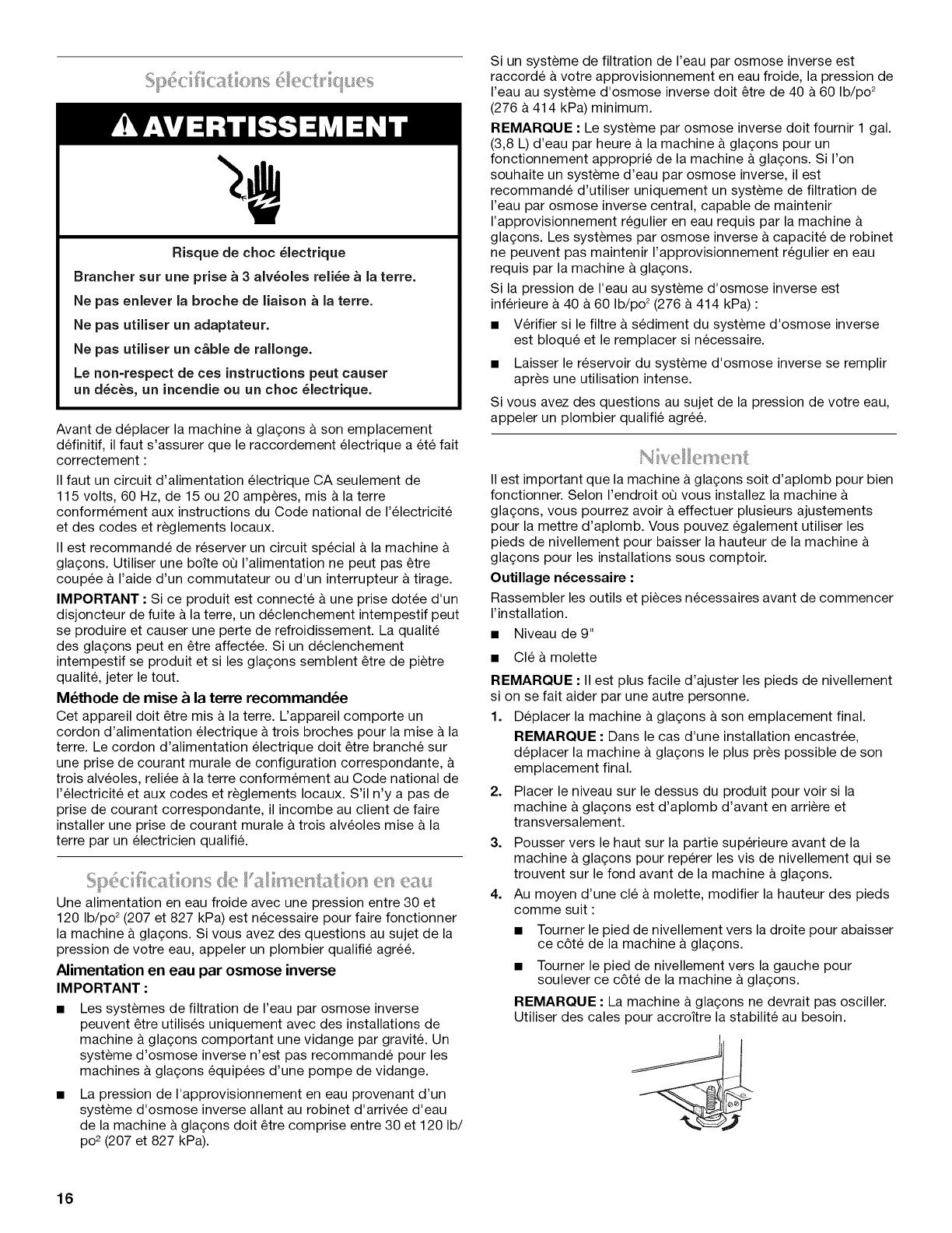
4. Au moyen d'une cle & molette, modifier la hauteur des pieds
comme suit :
Tourner le pied de nivellement vers la droite pour abaisser
ce c6te de la machine & glagons.
Tourner le pied de nivellement vers la gauche pour
soulever ce c6te de la machine a glagons.
REMARQUE La machine a glagons ne devrait pas osciller.
Utiliser des cales pour accroitre la stabilite au besoin.
16
5. Pousser vers le haut sur la partie superieure arriere de la
machine & gla(_ons pour reperer les pieds de nivellement qui
se trouvent sur le fond arriere de la machine a gla£;ons.
6. Suivre les instructions de I'etape 4 pour modifier la hauteur
des pieds.
7. Utiliser le niveau pour reverifier que la machine & gla£;ons est
d'aplomb d'avant en arriere et transversalement. Si elle n'est
pas d'aplomb, repeter les etapes 2 a 5. Si la machine est
d'aplomb, passer fl la section "Raccordement & la
canalisation d'eau".
Lire toutes les instructions avant de commencer.
IMPORTANT :
L'installation de la plomberie doit _tre conforme au Code
International de plomberie et respecter les codes et
reglements Iocaux de plomberie.
Utiliser un tuyau en cuivre ou le tuyau d'alimentation
Whirlpool, piece numero 8212547RP et verifier s'il y a des
fuites.
Installer les tuyaux seulement I&oQ les temperatures
resteront au-dessus du point de congelation.
Outillage n_cessaire :
Rassembler les outils et pieces necessaires avant de commencer
I'installation.
Tournevis a lame plate
Cles plates de 7Ae"et de V2"ou deux cles a molette
Tourne-ecrou de V4"
REMARQUE : Ne pas utiliser de robinet d'arr_t a etrier perforant
ou de 3Ae"(4,76 mm) qui reduit le debit d'eau et qui se bouche
plus facilement.
Raccordement du tuyau d'eau
1. Couper I'alimentation principale en eau. Ouvrir le robinet le
plus proche assez Iongtemps pour vider I'eau du tuyau.
2. A I'aide d'un tuyau d'alimentation en cuivre de V2"avec une
valve d'arr_t tournee de un quart de tour ou I'equivalent,
raccorder la machine & gla£;ons comme & I'illustration.
REMARQUE : Pour allouer un debit d'eau suffisant & la
machine & gla£;ons, un tuyau d'alimentation en cuivre de V2"
est recommand&
3.
On est maintenant pr_t & connecter le tuyau en cuivre. Utiliser
un tuyau en cuivre souple de W' (6,35 mm) de diametre
exterieur pour I'alimentation en eau froide.
S'assurer d'avoir la Iongueur necessaire pour le
raccordement. II faut s'assurer que les deux extremites
du tuyau en cuivre sont bien coupees a angle droit.
Installer le manchon et I'ecrou fl compression sur letuyau
en cuivre (voir I'illustration). Inserer I'extremite du tuyau
aussi profondement que possible dans I'extremite de
sortie et & I'equerre. Visser I'ecrou &compression sur
I'extremite de la sortie a I'aide d'une cle reglable. Ne pas
serrer a I'exces.
4=
A. Manchon _ compression
B. E-crou de compression
C. Tuyau en cuivre
D. Raccord (achet_)
Placer I'extremite libre du tuyau dans un contenant ou evier
et retablir I'alimentation principale en eau pour nettoyer le
tuyau jusqu'& ce que I'eau en sorte claire. Fermer le robinet
d'arr_t sur le tuyau d'alimentation en eau.
REMARQUE : Toujours vidanger le tuyau d'alimentation en
eau avant de faire le raccordement final sur I'entree du
robinet pour emp_cher tout mauvais fonctionnement
eventuel du robinet.
5. Courber le tuyau de cuivre de fa(_on fl faire un raccordement
sur I'entree du robinet qui se trouve &I'arriere de la machine &
gla£;ons (voir I'illustration). Laisser un serpentin de tube en
cuivre pour permettre de sortir la machine & gla£;ons du
placard ou du mur en cas d'intervention de service.
VUE ARRII_RE
B
E
A.Extr_mit_ renfl_e
B.Ecrou
A
B
6.
A. Bride pour tube d'arriv_e d'eau
B. Tuyau d'a_ration (seulement pour
modeles avec pompe de vidange)
C. Tube d'afimentation en d'eau
D. Bride pour tube d'admission d'eau
E. Tuyau de drainage (seulement pour
modeles avec pompe de vidange)
Retirer et jeter le tube court noir en plastique de I'extremite
du tube d'admission d'eau.
17
7,
Visser I'ecrou dans le raccord & I'extremit6 du tuyau. Serrer
I'ecrou manuellement. Ensuite le serrer deux tours de plus
avec une cl& Ne pas serrer a I'exces.
REMARQUE • Pour eviter les vibrations, veiller ace que les
tuyaux en cuivre ne soient pas en contact avec les parois
laterales de la caisse ou d'autres composants a I'interieur de
la caisse.
A B C D E F G
A. Canafisation jusqu'b
la machine _ glagons
B. E-crou (achet_)
C. Virole (achet_e)
D. Raccord (achet_)
E. Virole
F. Ecrou
G. Canalisation fournie
provenant de la
machine _ glagons
8. Installer la bride du tube d'alimentation autour de la
canalisation d'alimentation en eau pour reduire la tension sur
le raccord.
9. OUVRIR le robinet d'arr_t.
10. Verifier s'il y a des fuites. Serrer tous les raccords (y compris
les raccordements de la valve) ou les ecrous qui coulent.
Vidange par gravit_
II faut raccorder le tuyau de vidange de la machine a glagons
votre drain de vidange conformement aux codes et reglements
Iocaux et provinciaux. Si la machine &glagons est fournie avec
un drain de vidange par gravite, il faut suivre les instructions ci-
dessous Iors de I'installation des tuyaux de vidange. Ceci aidera
&eviter que I'eau ne refoule dans le bac d'entreposage de la
machine & glagons et eventuellement sur le plancher et ne cause
des dommages.
Les tuyaux de vidange doivent avoir au moins %" (15,88 mm)
de diam_tre interieur.
Les tuyaux de vidange doivent avoir une pente de 1" pour
chaque 48" (2,54 cm pour chaque 122 cm) de Iongueur ou
une pente de V4"pour chaque 12" (6,35 mm/30,48 cm) et ne
comporter aucun point bas oQ I'eau pourrait stagner.
Les drains de vidange de plancher doivent _tre suffisamment
grands pour recevoir I'eau de vidange provenant de toutes
sources.
L'installation ideale a un tuyau de rejet & I'egout avec un
reducteur de vidange PVC de 1V2" (3,81 cm) &2" (5,08 cm)
installe directement sous la sortie du tuyau de vidange
comme sur I'illustration. II faut maintenir un ecart anti-retour
de 1" (2,54 cm) entre le tuyau de la pompe de vidange et le
tuyau de rejet & I'egout.
II sera peut-_tre souhaitable d'isoler letuyau de vidange
completement jusqu'& I'entree du drain de vidange.
VUE LATleRALE
I
I
I !
17/8"
(4,8 cm) Y
1" (2,54 cm)
I
23" C
(58,4cm)
D
2" - 1Vd'
(5 cm - 3,8 cm)
A. Tuyau de vidange
B. E-cartanti-retour de 1" (2,54 cm)
C. R_ducteur du drain de vidange PVC
D. Le centre du drain devrait se trouver _ 23" (58,4 cm) du devant de
la porte avec ou sans le panneau de ¾" (1,91 cm) sur la porte. Le
drain dolt aussi _tre centr_ de gauche _ droite (7 _" [18,56 cm] de
chaque c6t_ de la machine _ glagons).
Syst_me avec pompe de vidange (sur certains modules)
Raccorder le drain de la machine & glagons au drain de vidange
conformement au Code international de plomberie et & tousles
codes et reglements Iocaux.
REMARQUE : Si le tuyau de vidange devient tordu et que I'eau
ne peut passe vidanger, votre machine & glagons ne
fonctionnera pas.
Raccordement du conduit d'_vacuation
Apr_s avoir verifie que le systeme de vidange est adequat, il faut
proceder tel que decrit ci-dessous pour bien mettre la machine
glagons en place
Risque de choc _lectrique
Brancher sur une prise a 3 alv_oles reli_e a Jaterre.
Ne pas enlever la broche de liaison a la terre.
Ne pas utiliser un adaptateur.
Ne pas utiliser un c&ble de rallonge.
Le non=respect de ces instructions peut causer
un d_c_s, un incendie ou un choc _lectrique.
1. Brancher sur une prise a 3 alveoles reliee a la terre.
18
Risque du poids excessif
Utiliser deux ou plus de personnes pour d_placer et
installer la machine a gla£ons.
Le non-respect de cette instruction peut causer
une blessure au dos ou d'autre blessure.
2. Style 1 - Pour un systeme de vidange par gravite, pousser la
machine & gla£_onsen position pour que le conduit de
vidange soit positionne au-dessus du reducteur de vidange
en PVC. Voir "Vidange par gravite" precedemment dans cette
section. Style 2 - Pour le systeme avec pompe de vidange,
connecter le tuyau de sortie de la pompe au drain. Voir
"Systeme avec pompe de vidange" precedemment dans
cette section.
3. Verifier & nouveau la machine & gla£;ons pour s'assurer qu'elle
est bien d'aplomb. Voir la section "Nivellement".
4. Si le code sanitaire local I'exige, sceller la machine sur le
plancher & I'aide d'un produit de calfeutrage approuve une
fois que les raccordements d'eau et d'electricite ont ete faits.
Outillage n_cessaire
Rassembler les outils et pieces necessaires avant de commencer
I'installation.
Cle de sAe" Couteau & mastic plat
Cle de W' Tournevis Phillips
Axe Vis de charniere _ t_te hexagonale
5_6"
Vis de poignde Vis d'embout
Depose de la porte
1. Debrancher la machine & gla£_onsou deconnecter la source
de courant electrique.
2. Oter les vis de la poignee et la poignee (sur certains
modeles). Garder les pieces ensemble et les mettre de c6t&
3. Tirer I'axe de la charniere superieure.
4. Retirer la porte des charnieres et revisser I'axe superieur dans
la charniere superieure.
5. Inverser les embouts de porte comme suit :
Retirer la vis et I'embout du coin superieur. Le deplacer en
diagonale vers le coin inferieur oppose, en gardant lec6te
droit de I'embout face a la machine a gla£_ons.
Retirer la vis et I'embout du coin inferieur. Le deplacer en
diagonale vers le coin superieur oppose, en gardant le
c6te droit de I'embout face a la machine a gla£_ons.
A B
D C
C D
0
:L___Jo
B A
A. Coin supdrieur ouvert (pas d'embout)
B. Ddbut de I'embout du coin supdrieur
C. Ddbut de I'embout du coin infdrieur
D. Coin infdrieur ouvert (pas d'embout)
6. Mettre la porte de c6t&
Inversion des charni_res
1. Devisser et 6ter la charniere superieure. Reinstaller les vis
dans les trous vides de charniere.
2. Oter les vis du c6te oppose inferieur de la caisse de la
machine a gla£;ons. Inverser la charniere superieure de telle
sorte que I'axe pointe vers le haut. Placer la charniere du c6te
oppose inferieur de la machine & gla_;ons et serrer les vis.
3. Enlever la douille de plastique de I'axe de la charniere de la
"vieille" charniere inferieure et la replacer sur la nouvelle
charniere inferieure.
4. Oter les vis de la "vieille" charniere inferieure et la charniere.
Reinstaller les vis dans les trous vides de la charniere.
5. Oter les vis du c6te superieur oppose de la caisse de la
machine a gla£;ons. Inverser la charniere de telle sorte que
I'axe pointe vers le bas. Placer la charniere du c6te oppose
superieur de la machine & gla£;ons et serrer les vis.
6. Oter I'axe de la charniere superieure.
R_installation de la porte
1. Placer ladouille de plastique de la charniere dans le trou de la
charniere superieure sur la porte. Aligner la porte avec le trou
de la charniere superieure et reinstaller I'axe superieur.
2. Reinstaller la poignee et les vis de la poignee.
19
Charni_re sup_rieure 3. Pousser les bouchons de trous en place du c6te oppose de
la porte.
D
A.Axe
B.Douillede I'axe de la charniere
C. Charniere
D. Visde charniere_ t_te hexagonale
Charni_re inf_rieure
.... _ ............. A
B
C
Risque de choc _lectrique
Brancher sur une prise a 3 alv_oles reli_e a la terre.
Ne pas enlever la broche de liaison a la terre.
Ne pas utiliser un adaptateur.
Ne pas utiliser un c&ble de rallonge.
Le non=respect de ces instructions peut causer
un d_c_s, un incendie ou un choc _lectrique.
J
A. Vis de charniere _ t_te hexagonale
B.Douille de I'axe de la charniere
C. Charniere
D. Axe
D
Inversion du Ioquet de porte
1. Oter les bouchons de trous du c6te oppose de la porte et les
mettre de c6t&
2. 0ter les vis du Ioquet de porte magnetique et les reinstaller
du c6te oppose de la porte.
4. Brancher sur une prise a 3 alveoles reliee a la terre.
II est possible que votre nouvelle machine & gla£;ons emette des
bruits qui ne vous sont pas familiers. Comme ces bruits sont
nouveaux, ils peuvent vous inquieter. La plupart de ces nouveaux
bruits sont normaux. Des surfaces dures comme le plancher, les
murs et les armoires peuvent faire paraftre les bruits plus forts
qu'en realit& Les descriptions suivantes indiquent les genres de
bruits qui peuvent _tre nouveaux pour vous et leur cause
possible.
Vous entendrez un bourdonnement Iorsque la valve d'eau
s'ouvre pour remplir le reservoir d'eau pour chaque
programme.
Des vibrations sonores peuvent provenir de I'ecoulement du
refrigerant, de la canalisation d'eau ou d'articles places sur la
machine a gla(;ons.
Le compresseur & haute efficacite peut produire un son aigu
ou de pulsation.
L'eau coulant sur la plaque d'evaporation peut produire un
son d'eclaboussement.
L'eau coulant de la plaque d'evaporation au reservoir d'eau
peut produire un son d'eclaboussement.
A la fin de chaque programme, vous pouvez entendre un
gargouillement attribuable au refrigerant qui circule dans
votre machine a gla£;ons.
Vous pouvez entendre de I'air qui est transmis au condenseur
par le ventilateur du condenseur.
Au cours du programme de recolte, vous pouvez entendre un
bruit sourd Iorsque la plaque de glace glisse de I'evaporateur
sur la grille de coupe.
Lors de la mise en marche initiale de la machine a gla£;ons, il
est possible que vous entendiez I'eau couler continuellement.
La machine &gla£;ons est programmee pour effectuer un
programme de rin£;age avant de commencer a fabriquer de la
glace.
20
  • Page 1 1
  • Page 2 2
  • Page 3 3
  • Page 4 4
  • Page 5 5
  • Page 6 6
  • Page 7 7
  • Page 8 8
  • Page 9 9
  • Page 10 10
  • Page 11 11
  • Page 12 12
  • Page 13 13
  • Page 14 14
  • Page 15 15
  • Page 16 16
  • Page 17 17
  • Page 18 18
  • Page 19 19
  • Page 20 20
  • Page 21 21
  • Page 22 22
  • Page 23 23
  • Page 24 24
  • Page 25 25
  • Page 26 26
  • Page 27 27
  • Page 28 28

Maytag MIM1554WRS0 Owner's manual

Type
Owner's manual
This manual is also suitable for

Ask a question and I''ll find the answer in the document

Finding information in a document is now easier with AI

in other languages