Carl Goldberg GPMA1993 Owner's manual

Category
Toys & accessories
Type
Owner's manual

This manual is also suitable for

WARNING
A radio-controlled model is not a toy and is not intended for persons under 16 years old. Keep
this kit out of the reach of younger children, as it contains parts that could be dangerous. A radio-
controlled model is capable of causing serious bodily injury and property damage. It is the buyer's
responsibility to assemble this aircraft correctly and to properly install the motor, radio, and all other
equipment. Test and fly the finished model only in the presence and with the assistance of another
experienced R/C flyer. The model must always be operated and flown using great care and common
sense, as well as in accordance with the Safety Code of the Academy of Model Aeronautics
(www.modelaircraft.org). We suggest you join the AMA and become properly insured prior to flying this
model. Also, consult with the AMA or your local hobby dealer to find an experienced instructor in your
area. Per the Federal Communications Commission, you are required to use only those radio frequen-
cies specified "for Model Aircraft."
LIMITED WARRANTY
Carl Goldberg Products has inspected and certified the components of this aircraft. The company urges the buyer to perform his
own inspection, prior to assembly, and to immediately request a replacement of any parts he believes to be defective for their
intended use. The company warrants replacement of any such components, provided the buyer requests such replacement with-
in a period of 90 days from the date of purchase and provided the defective part is returned, if so requested by the company.
No other warranty, expressed or implied, is made by the company with respect to this kit. The buyer acknowledges and under-
stands that it is his responsibility to carefully assemble the finished flying model airplane and to fly it safely. The buyer hereby
assumes full responsibility for the risk and all liability for personal or property damage or injury arising out of the buyer's use of the
components of this kit.
INSTRUCTIONS
CARL GOLDBERG PRODUCTS, LTD.
P.O. Box 818 Oakwood GA 30566 Phone #678-450-0085 Fax # 770-53-63 www.carlgoldbergproducts.com
© Copyright 2004 Carl Goldberg Products LTD.
Skylark 70
ARF
Designed as a first low-wing trainer over 26 years ago it is still a terrific everyday sport plane, the Skylark 70
ARF combines docile flight characteristics with the aptitude for super-smooth, exciting aerobatics. This ARF
has been designed to keep building time to a minimum; it's 90% pre-built, with premium covering. So read
through these instructions, follow them carefully, and you'll soon be flying a terrific plane. The better you get
the more fun it gives you!
TM
NOTE: The Skylark 70 ARF colors match Midnight
Blue(885), True Red(866) and White (#870)
UltraCote
®
.
2
TOOLS AND SUPPLIES FOR ASSEMBLY.
MODELING OR UTILITY KNIFE
WORK SURFACE (24" X70")
ELECTRIC DRILL
1/16”, 3/32”,1/8", 5/32”, 1/4” DRILL BITS
SMALL STANDARD & PHILLIPS SCREW-
DRIVERS
MASKING TAPE
NEEDLE NOSE PLIERS
36” RULER OR TAPE MEASURE
FLEXIBLE STRAIGHT-EDGE
T-SQUARE
30-60-90° x 6" TRIANGLE
SOFT PENCIL
A FEW STRAIGHT OR "T" PINS
ADJUSTABLE WRENCH
WIRE CUTTER
OPTIONAL HEAT GUN/COVERING IRON
ACID BRUSH
USING THIS INSTRUCTION MANUAL
Before you begin assembling your Skylark 70 ARF, take
some time to read through this entire instruction book. It is
designed to take you step-by-step through the process and
to give you added information on engine and radio selec-
tion and set-up, balancing your aircraft, and flying your
model. The time you spend will speed the assembly
process and help you avoid problems.
PREPARING FOR ASSEMBLY
You will need a work area of approximately 24 x 70" which has
been covered to protect it from adhesive, as well as cuts and
other damage. Many people cover their work area with a
sheet of dry wall (sheet rock) and/or waxed paper t o pre-
vent CAGlue and Epoxy from ruining the work surface.
CONSTRUCTION TIPS
IMPORTANT: ALWAYS READ A FEW STEPS AHEAD.
This will alert you to coming instructions and will help you
plan accordingly.
Using the Parts Identification section, familiarize yourself
with the various items included in your kit box.
As you work, CHECK OFF EACH STEP in the box provid-
ed, so that you are sure you do not forget anything.
Do not hesitate to ask questions. Your local hobby dealer
and area flyers will most likely be happy to help, as they
want you to have a successful flying experience. You may
also receive technical assistance from Carl Goldberg
Products, Ltd. via by telephone 1-678-450-0085.
ADHESIVES & GLUING TECHNIQUES
CA adhesives are specially formulated to firmly glue the
plywood, hardwood, and balsa used in your model and to
withstand the vibration and stresses of high performance
flight. However, there are times, such as when you are
installing the stabilizer and fin on the fuselage and want
more set-up time for careful alignment and positioning,
then you should use epoxy.. Occasionally, you also will
want to use thin CA, which "wicks" into the surrounding
areas. Aliphatic resin glue or similar water-based glues can
also be used, but they will add to the assembly time
because they dry so much more slowly than CA glue.
Remember, when ever using any CA, you must be careful
to read instructions thoroughly, as you will have only sec-
onds for positioning of parts. Be sure to trial fit parts
together before gluing. Also, never use watery THIN type
CA glue for gluing plywood and hardwood parts. Thin CA's
do not adequately bond these areas.
CAUTION
Some people may experience an allergic reaction when
exposed to fumes from CA glue or epoxy. As with paints,
thinners, and solvents, it is always important to use glues
only where there is adequate ventilation to carry fumes
away. A fan is recommended. Also, special care must be
taken when using CA, as it will bond skin as well as other
surfaces. Before using any CA, carefully read all label pre-
cautions. When using CA, protective eye-wear and care in
keeping the glue away from the face is highly recommend-
ed. If CA does happen to get into the eye, hold lid open
and flush with water only. Seek immediate medical atten-
tion.
Notice:
Before starting be sure all parts have
not been damaged during shipping.
Once assembly has been started, all
warranty on parts are void.
ITEMS NEEDED TO COMPLETE THIS AIRCRAFT
1 RADIO GUIDANCE SYSTEM (4 CHANNEL
MINIMUM REQUIRED, 5 STANDARD SER-
VOS )
2 6” EXTENSIONS
1 Y-HARNESS
1 ENGINE .61 2-CYCLE
1 ULTRA SET CA ACCELERATOR
1 ULTRA SET 2 OZ. BOTTLE MEDIUM CA
GLUE
1 ULTRA SET 1/2 OZ. BOTTLE THIN CA
GLUE
1 ULTRA SET 20 MIN EPOXY
1
1/2” FOAM RUBBER
1 SWITCH MOUNT
1 3” SPINNER
3
COVERING
The Skylark 70 ARF is covered in a premium polyester
film chosen by many of the world's top flyers for its beauty,
toughness, and ease of application and repair. It is not
uncommon for ARF's to develop a few wrinkles in transit. If
this is true of your model, the situation is easily corrected.
Before you begin putting the pieces together, run over out
side edges of the covering with an iron. This is to make
sure that the surface of the edges are sealed and will not
move when heat is applied to the center of the covering.
Then go over the center of each section with the iron
(either specially designed for airplane use or the more
cumbersome household iron) or use a modeling heat gun.
Apply the heat (set at about 350° F), following along with a
soft cloth and pressing down on the covering as you go
around. This will more firmly set the covering adhesive into
the wood and keep your aircraft covering tight and smooth
in the future.
One of the great advantages of polyester film is that it can
be applied over itself without causing gas bubbles. This
allows you to repair your aircraft, as well as to customize it
in a number of ways. If, due to a flight mishap, you get a
hole or similar covering damage, simply trim away the
ragged edges and then apply a patch, following the direc-
tions that come with your covering , which is available at
your hobby dealer.
RADIO EQUIPMENT & CARE
There are many fine radio systems on the market. Your
local hobby dealer and club members are good sources of
information on equipment and its suitability for various
projects. It is recommended that you speak to them before
making a final choice.
Today's RC systems are very well engineered and con-
structed. However, they will remain only as good as the
way in which they are USED. Always follow the rules of
proper usage and all manufacturer's instructions for your
particular piece of equipment.
TRANSMITTERS: Keep your transmitter clean and free
from fuel residue and dirt. Battery condition and RF output
should be monitored, and the system should be aligned
and tuned annually. Do not transport under vibration (such
as on the floor of a car) without cushioning.
RECEIVERS: Receivers must be vibration free. When
installing in the aircraft, wrap them in a minimum of ¼" soft
foam rubber (not plastic foam). Keep well clear of all
cables and batteries. Tune annually (or as recommended
by the manufacturer), as indicated below under "Check-
Ups."
SERVOS: Servos are vibration prone. Be sure to mount
them with grommet shock mounts in servo trays which are
also shock mounted. Also be sure to keep them clean. If
the neutral position "drifts," this is a sign of change which
should not be ignored; find out WHY before flying again.
BATTERIES: Nicads also can suffer from vibration, so they
too should be wrapped in soft foam rubber before installing.
Check their condition periodically by measuring the voltage
with a volt meter or battery tester. Charge the batteries
before EVERY flying session. When not used for a period
of time (such as during the winter months) the batteries
should be charged every 30 days. Never store batteries in
a discharged condition.
PUSHRODS: Obviously, pushrods should be installed to
operate freely, so that they place no load on the servo.
Using a servo's power to move a tight rod or heavy surface
by force increases the battery drain, shortens the electron-
ic life, and can cause neutralizing problems. In addition, it
is important the pushrods do not flex or vibrate. Any vibra-
tion is transferred directly to the servo, and its gear, motor,
and pot. To avoid flexing and vibration, use guides and fair-
leads on the rods.
CONNECTORS: In using connectors, never pull on the
wires to disconnect; grasp the plugs instead. Clean them
by dunking in a solvent, such as dope thinner. Tape the
connectors together when installing and make sure there is
no strain on the cables.
CHECK-UPS: A full check-up by the factory or an author-
ized service center should be done AT LEAST ONCE A
YEAR, as well as any time something unusual occurs dur-
ing usage. A malfunction or "glitch" is the first sign of an
impending failure; it should not be ignored. The checkup
should include tuning and alignment of the system, as well
as battery testing.
Important
Information
Covering coming loose is not
COVERED UNDER WARRANTY. Due to tem-
perature changes the plane may develop
some wrinkles in the covering that you will
need to remove with an iron. Be sure to seal
the edges down first so that you do not
cause the covering to shrink and leave
exposed areas of wood. Please inspect the
plane before beginning to assemble to make
sure you are happy with it. After assembly
has begun you cannot return the kit. If you
find a problem before beginning to assemble
the plane you must contact us, please do
not return it to the dealer.
Caution:
Before starting, care-
fully go over all high
stress areas with an
epoxy or wood glue to
confirm all areas are
well glued.
4
WING ASSEMBLY & INSTALLATION
AILERON INSTALLATION
1. Collect the following parts:
(1) Left wing
(1) Right wing
(1) Left aileron
(1) Right aileron
(8) CA hinge
1. Locate the pre-cut aileron hinge slots in both
wing halves. Using a hobby knife (#11 blade),
slide the blade into each slot to make sure it is
cleanly cut.
Repeat this process with the ailerons, making
sure all hinge slots are clean.
2. Place a straight pin into the center of each of
the four CA hinges.
Slide each hinge into the hinge slots on one of
the wing halves. The pin will prevent the
hinges from going in further than halfway into
the wing.
3. Select the aileron for the wing on which you
are working and insert the exposed half of
each hinge into the aileron slots.
Slide the aileron toward the wing until no gap
remains between the aileron and the wing.
4.
Carefully check the alignment of the aileron.
There should be about 1/32" on both ends.
When satisfied with the alignment, remove the
straight pins, being sure to keep the aileron
tight to the wing. You may wish to apply a few
pieces of masking tape to keep the pieces in
place.
5. Keeping the aileron and wing in position,
apply 3 or 4 drops of Ultra Set thin CA to the
small exposed area of each hinge.
Turn the assembly over and again apply 3 or
4 drops of Ultra Set thin CA to the exposed
hinge surfaces.
Allow to dry for 10 minutes before flexing the
aileron.
6. Repeat the above steps for the other half of
AILERON SERVO INSTALLATION
The following pictures may not exactly match the hard-
ware you are using. Always check the radio manufac-
turer's instructions when installing radio equipment.
1. Collect the following items:
(1) Wing
(2) Servos with rubber grommets installed
(8) Servo Mounting Screw (supplied with radio)
(2) servo extensions 6” long
2. Locate the string used to pull the wires
through the wing.
5
3. Plug the
servo extension wire into the servo .
Gently pull the string out of the aileron servo
hole and tie it or tape it to the servo wire.
From the top of the wing remove the covering
over the hole that is next to the center rib.
Pull the servo wire towards the center of the
wing using the string inside the wing.
When the servo plug exits the wing then tape
the plug to the top of the wing.
4. Slide the servo into the servo hole in the wing
with the out put arm towards the aileron.
Using the screws that come with your radio,
mount the servo into the wing.
Repeat these steps for the other half of the
wing, so that both servo extensions are exiting
the holes in the center of the wing and the ser-
vos are installed in the wing.
Aileron
AILERON CONTROL HORN INSTALLATION
1. Collect the following items
(2) Large control horn with back plate
(4) 3/4" screw
(2) Metal metal clevis
(2) 10” threaded rod
(2) Swivel keepers
2. With the aileron servo arm in place, make a
mark at a 90º degree angle to the trailing edge
and in line with the servo arm.
1.5mm x 20mm
MACHINE SCREWS
METAL CLEVIS
CONTROL
HORN
PLACE CONTROL HORN AT HINGE LINE
Bottom of wing
Wing is upside
down in this view
3. Position the control horn so that the clevis
holes are right next to the hinge line, as
shown.
4.
Using a 3/32" drill bit, make a hole in each
screw location.
Mount the control horn with the 1.5mm x
20mm machine screws.
5. Thread the 10" rod onto the metal clevis.
Make sure the rod shows in the center of the
metal clevis.
Place the metal clevis in the top hole on the
control horn.
6
6. Make sure the aileron is in neutral (level) posi-
tion, mark where the wire meets the hole on
the servo arm.
Remove the wire and cut it about 1/2" beyond
the mark.
Mark wire
7. Bend the wire 90 degrees up at the mark you
just made.
Slide the swivel keeper over the wire and clip
onto the pushrod.
Slide the silicone keeper over the clevis.
Repeat these steps for the other aileron servo.
MAIN GEAR & WHEEL INSTALLATION
1. Collect the following items:
(2) Landing gear wire
(8) 2 x 5/16"screw
(4) Landing gear strap
(3) 2-1/2" wheel
(4) Wheel collar
(4) Allen head set screw
2. Locate the landing gear slots in the bottom of
the wing and remove the covering material.
Insert the shorter end of the gear into the hole
in the bottom of the slot, so that it points
toward the center of the wing.
3.
Use two Metal straps and four screws on each
side to secure the wire gear.
4. Install the wheels on the axles, as shown.
First the wheel collar goes on, followed by the
wheel, then the second wheel collar, and the
set screw. Tighten the set screw.
AXLE
WHEEL
SET SCREW
WHEEL COLLAR
WHEEL COLLAR
PUSH ROD INSTALLATION
1. Collect the following parts
(2) 19-3/4” Wood dowels
(2) 1.5mm x 15cm wire
(2) 1.5mm x 20cm threaded wire
(2) Metal clevis
(4) shrink tubing
RUDDER ELEVATOR PUSHROD
2. Remove the metal clevis from the end of a 1.5
x 20cm wire.
Fuselage
7
3. Make a 90 degree bend.
Cut the wire 1/4” past the bend.
4. Insert the wire into the hole in the wood
pushrod and push down into the groove.
Glue the wire to the wood pushrod using Ultra
Set medium CA glue.
5. Slide the heat shrink tubing over the pushrod
and shrink using a blow drier.
Glue the tubing to the wood pushrod using
thin CA glue.
This finishes one end of the elevator pushrod.
1/4”
NON THREADED WIRE
6. Starting at the non-threaded end of the 1.5mm
x 15cm wire, bend the last 1/4” up at a 90
degree angle.
7. Insert the wire into the hole in the wood
pushrod and push down into the groove.
Glue the wire to the wood pushrod using Ultra
Set medium CA glue.
8. Slide the heat shrink tubing over the pushrod
and shrink using a blow drier.
Glue the tubing to the wood pushrod using
thin CA glue.
This finishes the elevator pushrod.
Repeat for the rudder pushrod.
INSTALLING PUSHRODS
1. Collect the following parts
(1) Elevator Pushrod
(1) Rudder Pushrod
(1) Fuselage
2. Find the hole under the stabilizer on both
sides of the fuselage.
Cut the covering over each of the push rod
exit holes. Note that there are two slots on
each side. Use the one closes to the stab on
the right side (elevator) and the lower one on
the left side (rudder).
3. Insert the rudder pushrod into the fuselage
through the wing saddle area.
8
WING INSTALLATION ON FUSELAGE
2. Insert the wing into the wing saddle of the
fuselage by sliding the dowels on the front of
the wing into the holes in the former just for-
ward of the wing saddle.
Insert two 3.5mm socket head screws and the
3.5mm washers through the wing and then
begin to screw into the blind nut in the fuse-
lage. Screw down until the screws are touch-
ing the wing tight.
4. Insert the wire into the hole in the right side of
the fuselage.
Repeat these steps for the rudder pushrod
making it exit the left side of the fuselage.
Tape the pushrods to the side of the fuselage
inside the wing saddle area.
1. Slide the aluminum wing tube into one wing
panel.
Slide the other panel on till the wings butt
together.
STAB & ELEVATOR INSTALLATION
1. Collect the following parts:
(1) Stabilizer
(2) Elevator
(1) Wing/fuse assembly
(6) CA hinges
(1) Elevator joiner Wire
2. As with the wing and ailerons, use a modeling
knife to make sure the hinge slots are cleanly
cut.
3. Place the stab on the fuse and align the cen-
ter slot with the front slot and the rear of the
fuselage.
4.
Slide the fin into the slot in the fuselage and
the stab.
Push the fin all the way into the slot till it stops.
Tape the fin onto the fuselage.
5.
Mark the bottom of the stab along the fuse-
lage.
Mark where the fin sits on top of the fuselage
both in front and rear.
Mark where the fin slides down into the stab
and the fuselage.
9
6. Remove the stab from the fuse and, working
1/8" inside the drawn lines, carefully remove
the covering from the bottom of the stab, both
sides of the fin and the top of the fuselage. BE
CAREFUL TO AVOID CUTTING THE WOOD
7. Re install the stab back onto the fuselage.
Place the metal elevator joiner at the rear of
the stab next to the fuselage.
Make sure the joiner twist easily up and down
and is centered.
7. Make sure the stab is level (parallel) with the
wing and insert paper strip shims under the
low side of the stab, if necessary.
Remove the stab & fin from the fuse.
9. Spread epoxy on both the bottom of the stab,
fin and the fuselage where the fin will rest.
Replace the stab on the platform and the fin
into the slots, after again checking the align-
ment of the stab to the wing, tape together
and allow the epoxy to dry thoroughly.
10. As with the installation of the ailerons, insert a
straight pin in the center of 6 CA hinges.
Mix up a small amount of epoxy and insert it
into the hole in the elevator where the wire
elevator joiner fits.
Slide the hinges halfway into the elevator and
then slide the entire assembly into the hinge
slots in the stabilizer making sure the wire
joiner is inserted in the hole and groove .
Make sure the elevator is flush with the end of
the stab. If desired, tape the elevator to the
stab to keep the pieces together.
11.
Keeping the stab and elevator in position,
remove the pins and apply 3 or 4 drops of thin
CA on to each hinge location.
Repeat steps 10 & 11 for the other elevator.
Allow the elevator/stab assembly to dry for at
least 10 minutes before flexing the elevator.
10
12. Insert a straight pin in the center of 3 CA
hinges.
Slide the hinges halfway into the rudder and
then slide the entire assembly into the hinge
slots in the fin.
Make sure the rudder is flush with the top of
the fin. If desired, tape the fin to the rudder to
keep the pieces together.
13.
Keeping the fin and rudder in position, remove
the pins and apply 3 or 4 drops of thin CA on
to each hinge location.
Allow the rudder / stab assembly to dry for at
least 10 minutes before flexing the elevator.
Remove the wing from the fuselage.
CONTROL HORN INSTALLATION
1. C
OLLECT THE FOLLOWING PARTS
(2) Nylon Control Horns with Base Plates
(2) 1.5mm x 20mm Machine Screws
(2) 1.5mm Metal Clevis
(2) Silicone Clevis Keepers
(4) Shrink Tubing
2. Position the control horn so that the metal cle-
vis holes are right next to the hinge line, as
shown.
3.
Using a 3/32" drill bit, make a hole in each
screw location.
Mount the rudder control horn using the 1.5 x
20mm machine screws & base plates.
Place the silicon keeper over the end of the
pushrod and twist the metal clevis onto the
threads.
Attach the metal keeper to the control horn.
Slide the silicone keeper over the clevis till it
touches the control horn.
MARK HOLE LOCATIONS
4. Repeat steps 2 & 3 for the rudder control horn.
SERVO INSTALLATION
1. C
OLLECT THE FOLLOWING PARTS
(3) Servos with mounting screws
(2) Nylon Swivel Keepers
2. Mount servo as shown in tray.
11
3. Tape the elevator so that it stays in the neutral
position.
Align the servo arm so that it is sitting at 90
degrees to the servo.
Mark the location where the elevator pushrod
wire meets the outer hole of the servo arm.
Forward
4. Bend the wire up 90 degrees at that mark.
Slide the swivel keeper over the end of the
pushrod and snap to the wire.
5. Repeat steps 1 thru 4 for the rudder servo.
5. Install the e-z connector on one end of the
servo arm
NOSE GEAR INSTALLATION
1. COLLECT THE FOLLOWING PARTS
(1) Nose gear strut
(3) Wheel Collars and set screws
(1) Wheel
(1) Nose gear steering arm
(1) 1.5mm x 43 cm wire and tube
(1) EZ connector and screw
(1) Nylon Swivel Keeper
2. Slide a wheel collar with a set screw onto the
top of the nose gear gear strut.
4. Insert the nose gear strut thru the hole on the
bottom of the fuselage.
Adjust the strut so that the coil is just off the
bottom of the fuselage.
When satisfied, tighten the wheel collar set
screw.
Holding the strut up inside the fuselage, turn
the fuselage over.
12
5. Slide the steering arm on the top of the nose
gear strut.
There is a flat spot on the front side of the strut
rotate the strut till it is pointing backwards and
the set screw aligns with the flat spot
Tighten the screw in the steering arm as
shown above.
7. slide the push rod tube through the former and
into the fuel tank compartment.
Insert the 1.5mm wire into the tube and con-
nect the clevis to the arm.
6. Rotate the nose gear around into position.
8. Slide the nose gear wire into the hole in the
EZ connector and center the servo arm and
the nose gear wheel.
When satisfied, tighten the set screw on the
EZ connector.
ENGINE INSTALLATION
1. COLLECT THE FOLLOWING PARTS
(1) ENGINE
(6) #6
X 3/4SHEET METAL SCREWS
(3) MOTOR MOUNT PLATES
(1)
SPINNER (3” NOT INCLUDED)
9. Install the nose gear with a wheel collar on
each side.
2. Locate the 1/4” motor mounting plate. This is
designed as a break away plate. Drill six 9/64”
holes in the approximate position shown. The
location is not critical, just make sure not to
put them where the engine will sit.
13
3. Place the mount into the front of the fuselage.
Make sure that the smaller side beam is on
the left side of the fuselage.
The motor mount should point a little to the
right about 2 degrees. Mark the top of the
plate.
Left side of the fuselage
Gap
4. Slide the engine into the motor mount and
through the front nose ring.
Open the spinner and place the spinner back
plate onto the engine. This will help to center
the front of the engine to the fuselage
Make sure that there is a clearance between
the spinner back plate and the front of the
fuselage .
4. Mark the location of the engine mounting
holes.
Also at this time mark the location of where
the throttle pushrod should exit the firewall.
Remove the engine and the motor mount
plate.
5. Drill the engine mounting holes in the plate.
6. Drill the hole for the engine throttle pushrod.
14
7. Install the T-nuts on the bottom side of the
mount.
Bolt the engine to the mount plate.
8.
Re-install the engine and plate into the fuse.
Mark the location of the six holes you drilled in
the plate on the beams.
Drill a 3/32” hole at the marks and use six
#6x3/4” screws to secure the plate.
2. Slide the throttle pushrod tubing into the hole
in the firewall that you drilled earlier.
Attach the clevis to the engine throttle arm.
Hole
3. Make a notch in the bulkhead for the nylon
tube to fit into.
THROTTLE PUSH ROD INSTALLATION
1. COLLECT THE FOLLOWING PARTS
(1) 1.5
MM X 40CM
(1) NYLON TUBE
(1) NYLON CLEVIS.
notch
4. Place the EZ connector on the throttle servo
arm just as you did earlier.
Slide the throttle pushrod through the EZ con-
nector and adjust as necessary.
1. G
ATHER THE FOLLOWING ITEMS
(1)
FUEL TANK
(1) RUBBER TANK STOPPER
(1) CLUNK
(1) 3
MM X 25MM SCREW
(1) CAP WASHER LARGE
(1) CAP WASHER SMALL
(1) 3
MM X
40MM BRASS TUBE
(1) 3MM X 60MM BRASS TUBE
(1)
SILICONE TUBE 4
MM X 80MM
(2)
SILICONE TUBE 5MM X 165MM
FUEL TANK ASSEMBLY
15
2. Insert the 3mm screw through the center
hole in the large washer, through the center
hole in the rubber washer against the large
side, and screw the small washer on the
back side.
3. Insert the brass tubes through two of the
holes. They should be arranged so as the long
one will be on the right side of the plane and
the short one on the left side.
The tubes should extend out the front of the
cap 5/8”. Bend the long tube up at about a 20
degree angle. This should be adjusted so the
end of the tube almost touches the top of the
tank when installed.
4, Install the 4mm silicone tube to the short
brass tube and install the clunk to the other
end of the silicone tube. This is the fuel pick-
up and must be free to “flop” around in the
tank so it can pick up fuel in any attitude.
5. Install the assembly into the tank so the vent
tube is turned up to the top of the tank and is
positioned on the right side of the tank.
Tighten the screw to expand the rubber cap.
Don’t over tighten or you could split the tank.
6. Attach the two pieces of 5mm tubing to the
two tank outlets. Make a note of which one
you attach to which tube. The short brass with
the clunk is the fuel pickup and must go to the
carburetor. The long brass tube is the vent
and should go to the pressure outlet on the
muffler.
INSTALLING FUEL TANK
1. Insert the fuel tank through the hatch opening
area and feed the fuel lines through the hole
in the firewall.
Slide the tank all the way forward till the brass
tubes pass through the firewall hole.
Attach the fuel lines to the motor.
Place some foam (Not included) around the
tank to prevent it from sliding back out of the
fuel compartment.
2. install the fuel tank hatch on top of the fuse-
lage with 2mm sheet metal screws on both
sides of the fuselage.
16
RADIO SWITCH, RECEIVER, BATTERY
1. We mounted the receiver and battery in front
of the servo tray. Depending on what engine
you us, you might need to move the battery
pack forward in to the fuel tank compartment.
2. Mount the radio switch through the side of the
fuselage opposite the engine exhaust.
COCKPIT, CANOPY AND PILOT
The pilot figure included with your airplane adds an
extra touch of realism.
APPLY DABS OF GLUE AT
JOINTS
WHEN DRY, REMOVE
TAPE AND COMPLETE
GLUING
1. Cut pilot halves apart at the bottom and trim
off scrap. Remove the bottom of the pilot just
below his neck. Gently sand the edges of
each half, so that they will be smooth for join-
ing. Carefully align the front and back pieces
and hold together with tape, as shown.
1. Tack glue the figure by applying a few drops of
CA glue at key joint areas. When dry, remove
tape and apply a small amount of glue all
along the seam.
PAINT PILOT AS
DESIRED
Cut line
Using artist's acrylics or modeling enamels,
paint the pilot to suit your fancy. WARNING:
Do not use lacquer-based paints, which will
destroy the plastic.
When dry, CA glue the pilot in place on the
cockpit. You also may paint the cockpit, if
added realism is desired.
HINT: WHEN PAINTING THE PILOT'S FACE, LEAVE THE EYES
WHITE
. LATER, WHEN THE FACE HAS DRIED, CAREFULLY ADD
EYE DETAILS WITH A FINE BUSH OR TOOTHPICK.
2. Sand the glue edge of the cockpit insert
smooth, try to get the cockpit insert as flat as
possible. Using canopy glue, glue the cockpit
insert to the top of the fuselage and hold in
place with tape.
When dry, remove the tape and glue the pilot
in place.
Glue the canopy in place and hold with tape till
dry.
17
BALANCING
IMPORTANT: NEVER NEGLECT THIS STEP WITH
ANY AIRPLANE. If you try to fly a plane with the
balance point behind the recommended range,
you run the risk of having an unstable aircraft and
the strong likelihood of a crash. TAKE THE TIME
TO PROPERLY BALANCE YOUR MODEL!
To determine the Center of Gravity, measure back on
the fuselage
3-1/2" from the leading edge of
the wing.
The C.G. range for this aircraft is 3 1/4” to 3-
3/4".
Place the fully assembled aircraft on a model balanc-
ing stand, as shown above. You can make this simple
set-up with a couple of ¼" dowels with rounded tops,
spaced 5" apart. Alternatively, lift the model under the
wing near the fuse by your finger tips. (You may wish
to get help from a friend if using the latter method.)
Referring to the recommended balance range for
your model, move the position of the plane on the bal-
ance stand until the model is level or the nose slight-
ly down. If the is tail heavy, shift the R/C equipment
away from the heavy end of the model and recheck
until the model will balance within the acceptable
range. If shifting the R/C gear still doesn't balance the
model, add weight to the far end of the nose or tail,
respectively, until the model is correctly balanced.
The least weight is needed when added as far back
or forward as possible. Fasten the weight perma-
nently in place.
APPLYING DECAL
1. Using glass cleaner and a soft cloth, clean
model surface thoroughly before applying the
decal.
Cut the decal sheets apart in sections, as
needed. Fold the decal in half, front to rear.
Open at the fold and lay the decal out straight.
The protective backing will bubble away from
the decal at the fold.
Using a scissors, cut the backing along the
bubble, removing a strip of backing about 1"
wide. Carefully position the decal on the
model and stick it in place. Then, working
from the center, rub the decal down while
peeling off the remainder of the backing.
18
FLYING YOUR SKYLARK 70 ARF
GETTING READY TO FLY
BEGINNING AEROBATICS
Taking time here really pays off later. Rushing the set-
up and testing frequently results in a model that never
performs up to its full potential and may even lead to a
crash.
CONTROL SURFACE SETTINGS. For the first few
flights, even if you are an experienced flier, it is best to
set the control surfaces at the GENTLE (LOW) set-
tings. You can then work your way up to the higher set-
tings. The settings for the SKYLARK 70 ARF are:
LOW HIGH
AILERONS 3/8” 1/2"
ELEVATOR 1/2” 3/4"
RUDDER 1" same
RADIO CHECK. Many an experienced flier has rued
the day he neglected to check EVERYTHING! After
fully charging the batteries, turn on the receiver and
transmitter and actuate all controls many times to make
sure all responses are correct. Standing behind the
model, the right aileron should go up when the stick is
moved to the right. Moving the transmitter stick down
should move the elevator up, and vice versa. Also
check the wheel movement, which should move right
with the right rudder movement. Check that the throttle
opens to permit full power when the stick is moved up.
Practice steering the model on the ground, with the
throttle set at minimum, to keep model moving at a
walking pace. Before and after all tests, make sure all
gear is neatly and firmly in place - engine and servos
fastened down, receiver and battery wrapped in foam
and secured against shifting, propeller tight, and anten-
na extended.
Prior to the beginning of each day's flying, make a
range check of your equipment in accordance with the
manufacturer's instructions. With transmitter antenna
collapsed to 6-8", you should have at least 100 feet
range on the ground. Check this by turning on both the
receiver and transmitter and with the model heading
away from you, walk away while transmitting signals.
Watch to see that no signals are missed until you are
at least 100 feet away. Remember not to use your
transmitter when someone else is flying or testing
on the same frequency. DO NOT ATTEMPT FLIGHTS
UNLESS ALL THE EQUIPMENT WORKS PERFECTLY.
After everything checks out, check it again! When you
are satisfied with the performance of all equipment
functions, point your TIGER'S nose into the wind and,
gradually increasing to full power, take off for a short (2
to 3-minute) first flight.
Before the second flight, take off the wing
and check all screws, radio equipment,
engine mounting, muffler, etc. to make
sure that nothing has come loose.
Spend the following flights getting famil-
iar with your model and making sure it is
properly trimmed for straight and level
flight. When you feel comfortable with your model, it's
time to try aerobatics.
Almost all maneuvers are a combination of loops
and rolls, so if you can do these two things, you're off
to a good start! We highly recommend the book
Flight Training Course, Volume II, published by
R/C Modeler Magazine. Some of the following is
taken from this manual, with the gracious permission
of the magazine.
Above all, remember that top gun aerobatics are the
result of practice. The crisp, graceful movements
come from the pilot's willingness to do and do it again.
Don't give up; practice really does make perfect!
Which side is up? Learning to recognize which side
is up may sound foolish, but many a plane has bitten
the dust because the pilot lost track of the plane's
position. Other than learning to recognize the plane's
silhouette at different angles and attitudes, the best
insurance is to force yourself to concentrate on each
thing that you do, i.e. making a left turn. If your mind
strays and you forget what you're doing, coming
back to it can cause a few new grey hairs!
THE LOOP. This is a good first stunt. The model
starts flying straight and level into the wind, then
pulls up into a smooth, round loop. The up and down
portion should be straight, without the plane falling
off to the right or left, and the speed should be con-
stant. As the plane finishes the loop, it pulls out
straight and level, at the same heading and altitude
as when it entered the maneuver.
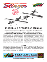
THE HORIZONTAL ROLL. Important! Always
remember that, when the plane is inverted, the
elevator works backwards. Therefore, when the
plane is inverted, you give down elevator. Also, be
sure to fly high enough to give a good margin for
error, as your early attempts will probably end up in
a 30º dive. We also recommend you practice with
the plane in front of you, rather than overhead.
Good luck and happy flying!
2. DOWN ELEVATOR
4. UP ELEVATOR
3. RELEASE AILERON
CONTROL
1. FULL RIGHT OR
LEFT AILERON
WIND
WIND
(OPTIONAL, BUT
GIVES A MORE PRE-
CISE LOOP
1. UP ELEVATOR
2. EASE OFF OF SOME
UP ELEVATOR
5. EASE OFF OF UP ELEVA-
TOR, OPEN THROTTLE
3. ADD SOME UP ELEVATOR
4. THROTTLE DOWN TO IDLE
75-150 FT.
  • Page 1 1
  • Page 2 2
  • Page 3 3
  • Page 4 4
  • Page 5 5
  • Page 6 6
  • Page 7 7
  • Page 8 8
  • Page 9 9
  • Page 10 10
  • Page 11 11
  • Page 12 12
  • Page 13 13
  • Page 14 14
  • Page 15 15
  • Page 16 16
  • Page 17 17
  • Page 18 18

Carl Goldberg GPMA1993 Owner's manual

Category
Toys & accessories
Type
Owner's manual
This manual is also suitable for

Ask a question and I''ll find the answer in the document

Finding information in a document is now easier with AI