Page is loading ...

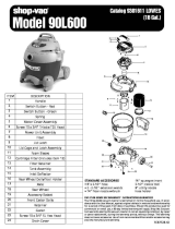
ITEM DESCRIPTION PART NO.
1 Cover 85550-01-0
2 Motor housing 88540-00-0
3 Screw #8 x %" Ph pan hd., type AB 15063-99-3
4 Power cord (12') 04292-96-7
(18') 04293-96-5
5 Switch 82303-04-1
6 Strain relief bushing 34004-99-4
7 Wire nut 05001-99-5
8 Upper motor gasket 20700-00-1
9 Ground screw 17008--99-6
10 Motor 17300-97-1
11 Lower motor gasket 20716-00-7
12 Grid plate 88607-00-7
13 Ball float 00811-00-0
14 Lid latch 85501-01-3
15 Lid cage & latch assembly 89887-14-5
16 Cartridge filter 90304-62-7
17 Foam sleeve 90585-62-1
18 Filter retainer 30080-00-6
19 Screw #10 x 1" hex head, type AB 15096-99-3
20 Tank assembly (includes inlet)
(S.S.) 10466-97-7
(painted) 51045-96-1
21 Handle package (includes 2 93551-96-8
handles and 4 mounting screws)
22 #10 x
3
/4" screw hex head 15039-99-3
23 Inlet fitting 21720-01-6
24 #10 x
5
/8" screw hex head 15054-99-2
Standard Accessories:
12' (3.66 m) x 1
1
/' (3.81 cm) Hose
(2) 1
1
/2" (3.81 cm) Metal extension wands
14" (35.56 cm) Metal nozzle
14" (35.56 cm) Squeegee insert
14" (35.56 cm) Brush insert
SC87517-32

7
ITEM DESCRIPTION PART NO.
1 Cap nut 43002-99-7
2 8" Wheel 24250-10-2
3 Axle 24408-00-7
4 Rear frame 93921-96-3
5 Caster socket 75405-00-1
6 Front frame 93920-00-7
7 #8 x
1
/2" lg. Screw 15015-99-3
8
1
/4 - 20 x
3
/4" lg. machine screw 09029-99-2
9
1
/4" Flatwasher 07003-99-9
10
1
/4 - 20 Hex nut 13001-99-5
11 Caster 67736-00-9
Dolly Assembly
1. Remove head from tank and place tank upside down on
a flat surface.
2. Place wheels on rear frame/axle assembly with extended
hub towards dolly frame and place cap nut on axle.
Secure with hammer.
3. Insert caster socket into front frame and secure with
phillips head screw.
4. Place groove in front frame into lip of tank and position
so frame is directly above inlet.
5. Position grooves of rear frame on lip of tank and align so
rear and front frames engage.
6. Secure dolly frame to tank by placing machine screws
up through holes in dolly frame.
Ensure head of screw is fully recessed in area provided.
After machine screw is inserted, tighten with
flatwasher and hex nut.
7. Insert caster in caster socket and apply downward
pressure until caster snaps into place.
8. Stand vacuum up on dolly. Place metal carriage handle
between tank and side handles, and fasten
tightly with screws provided. Be sure to spread ends of
carriage handle when assembling to prevent damage
to tank.
ITEM DESCRIPTION PART NO.
1 Metal tank handle 20811-01-4
2 Side tank handle 93551-00-0
3 #10 x
3
/4" Screw hex head 15039-99-3
/


