Page is loading ...

P/N# 240009137, Rev. A [02/2012]
D248 Series
Cast Iron Commercial
Steam Boiler
INSTALLATION, OPERATION &
MAINTENANCE MANUAL
An ISO 9001-2008 Certified Company
2201 Dwyer Avenue, Utica NY 13501
web site: www.ecrinternational.com

2
INSTALLATION MANUAL AND OPERATING INSTRUCTIONS
SAFETY SYMBOLS
TABLE OF CONTENTS
Safety Symbols .................................................. 2
Boiler Ratings & Capacities .................................. 3
Rules For Safe Installation & Operation .................. 4
Locating The Boiler ............................................. 5
Combustion Air, Chimney & Vent Pipe Connection ... 5
Minimum Vent Pipe Clearance, ............................. 5
Installation ........................................................ 5
Ventilation And Combustion Air ............................ 6
Vent Installation ................................................. 8
Assembly Of Bases, Starting Section Assembly ......12
Attaching Draft Hoods .........................................13
Installing Boiler Jacket Panels ..............................14
Control Mounting And Installation .........................17
Tappings ...........................................................19
Boiler Trim, Water Trim, Water Trim Assembly...........19
Boiler Piping ......................................................20
Boilers Used With Refrigeration System ..................20
Boiler Piping, High Limit, Pipe Sizing ......................20
Piping Diagrams ................................................21
Connecting Gas Service ......................................23
Electrical Wiring .................................................24
Installing Thermostat ..........................................24
Adjust Thermostat Heat Anticipator .......................24
Stage Firing Multiple Base Boilers ..........................24
Wiring Diagrams ................................................25
Operation and Service .........................................27
Functions & Operation, Trial/Pilot Ignition ..................27
Main Burner Operation, System Troubleshooting .........27
Component & Spark Ignition Check ........................27
Startup & Checkout, Start system..........................28
Pilot Flame Adjustment, Check Burner Input ............28
Pilot System Troubleshooting Table ............................29
Checking & Adjusting .........................................30
Cleaning And Maintenance ..................................31
KEEP THIS MANUAL NEAR BOILER.
RETAIN FOR FUTURE REFERENCE.
CAST IRON HOT WATER OR STEAM BOILER
DANGER
Indicates a hazardous situation which, if not avoided,
WILL result in death or serious injury.
!
WARNING
Indicates a hazardous situation which, if not avoided,
could result in death or serious injury.
!
NOTICE
Indicates information which should be followed to ensure
proper installation and operation.
CAUTION
Indicates a hazardous situation which, if not avoided,
could result in minor or moderate injury.
!
!
WARNING
Fire, explosion, asphyxiation and electrical shock hazard.
Improper installation could result in death or serious in-
jury. Read this manual and understand all requirements
before beginning installation.
!

3
1) Ratings are at sea level to 2,000 feet. For altitudes above 2,000 feet, reduce all ratings 4% for each 1,000 feet above sea level
2) Net steam ratings based on an allowance of 1.333 (300-1600), 1.327 (1700), 1.319 (1800), 1.313 (1900), 1.307 (2000), 1.301 (2100), 1.296 (2200),
1.292 (2300), 1.290 (2400), and 1.288 (2500-3000). Contact Technical Support before selecting boiler for installations having unusual piping and pick-up
factors, such as intermittent system operations, extensive piping systems, etc.
3) Ratings in square feet are computed at 240 Btuh/square foot for steam boilers.
4) Ratings based on 33,500 Btuh per horsepower.
5) Pressure drop based on given fl ow from single outlet and returning to single inlet at the opposite end of the boiler.
6) Chimney sizes shown are one option based on a typical venting system as shown in Figure 6, and sized according to the National Fuel Gas Code, assuming Type B
double wall vent and vent connectors, Other venting system designs are acceptable as shown on Flue Connection And Venting section of this manual. For further
chimney design and sizing information, consult the National Fuel Gas Code, ANSI Z223.1/NFPA 54-latest revision, or ASHRAE6 HVAC Systems and Equipment Handbook,
Chimney, Gas Vent, and Fireplace Systems, or the Standard for Chimneys, Fireplaces, Vents, and Solid Fuel Burning Appliances. NFPA 211. Follow standard engineering
practice.
Ratings and Capacities - Chart 1
Input/Size
(Mbh)
Output (1)
Net AHRI
Ratings (2)
Flue Outlet No.
& Size
Chimney
Size (6)
Flue
Collector
Size to
Chimney
Horsepower
Gross
Output (4)
Therm.
Eff.
Pressure Drop
Thru Water
Boiler (5)
Gross
Output
Mbh
Steam
(Sq Ft)
Steam
Mbh
8” 10” 12” I.D. x Ht.
GPM
In.
Water
300
400
500
233
310
388
729
971
1213
175
233
291
1
1
1
8”x20’
10”x20’
12”x20’
8
10
12
6.96
9.25
1
1.58
77.5
18.9
37.8
0.10
0.50
77.5
25.2
50.4
0.27
0.86
77.5
31.5
63.0
0.40
1.20
600
700
800
900
1000
465
543
620
698
775
1454
1696
1938
2183
2421
349
407
465
524
581
2
11
2
11
2
12”x20’
12”x20’
14”x20’
14”x20’
14”x20’
12
12
14
14
14
13.88
16.21
18.51
20.84
23.13
77.5
37.8
75.6
0.50
1.70
77.5
44.1
88.2
0.70
2.50
77.5
50.4
100.8
0.88
2.90
77.5
56.7
113.4
1.10
3.80
77.5
63.0
126.0
1.30
4.00
1100
1200
1300
1400
1500
853
930
1008
1085
1163
2667
2908
3150
3392
3633
640
698
756
814
872
1
1
2
3
1
2
2
3
16”x20’
16”x20’
16”x20’
18”x20’
18”x20
16
16
16
18
18
25.46
27.76
30.09
32.39
34.72
77.5
69.3
138.6
1.50
5.00
77.5
75.6
151.2
1.80
6.00
77.5
81.9
163.8
2.00
5.60
77.5
88.2
176.4
2.40
7.00
77.5
94.5
189.0
2.60
8.30
1600
1700
1800
1900
2000
1240
1318
1395
1473
1550
3875
4138
4408
4675
4942
930
993
1058
1122
1186
1
4
1
2
1
2
2
3
4
18”x20’
18”x20’
20”x20’
20”x20’
20”x20
18
18
20
20
20
37.01
39.34
41.64
43.97
46.27
77.5
100.8
201.0
2.80
9.60
77.5
107.1
214.2
3.15
10.30
77.5
113.4
226.8
3.50
11.00
77.5
119.7
239.4
4.00
12.50
77.5
126.0
252.0
4.50
14.00
2100
2200
2300
2400
2500
1628
1705
1783
1860
1938
5213
5483
5750
6008
6271
1251
1316
1380
1442
1505
2
3
2
1
3
2
3
4
5
20”x20’
22”x20’
22”x20’
22”x20’
22”x20
20
22
22
22
22
48.60
50.90
53.22
55.52
57.85
77.5
132.3
264.6
4.95
16.00
77.5
138.6
277.2
5.40
18.00
77.5
144.9
289.8
5.70
17.00
77.5
151.2
302.4
8.00
19.00
77.5
157.5
315.0
8.00
20.50
2600
2700
2800
2900
3000
2015
2093
2170
2248
2325
6517
6771
7021
7271
7521
1564
1625
1685
1745
1805
2
11
2
1
4
4
4
5
6
22”x20’
24”x20’
24”x20’
24”x20’
24”x20
22
24
24
24
24
60.15
62.48
64.78
67.10
69.40
77.5
163.8
327.6
7.00
24.00
77.5
170.1
340.2
7.50
24.00
77.5
176.4
352.8
8.00
26.00
77.5
182.75
365.5
8.50
27.50
77.5
189.1
378.2
9.00
9.00
RATINGS AND CAPACITIES

4
Safety Information
IMPORTANT: Read the following instructions
COMPLETELY before installing!!
WARNING
Fire, explosion, asphyxiation and electrical shock
hazard. Improper installation could result in death
or serious injury. Read this manual and understand
all requirements before beginning installation.
!
WARNING
Keep boiler area clear and free from combustible
materials, gasoline and other fl ammable vapors
and liquids.
DO NOT obstruct air openings to the boiler room.
Modifi cation, substitution or elimination of factory
equipped, supplied or specifi ed components may
result in personal injury or loss of life.
TO THE OWNER - Installation and service of this
boiler must be performed by a qualifi ed installer.
TO THE INSTALLER - Leave all instructions with
boiler for future reference.
When this product is installed in the
Commonwealth of Massachusetts the installation
must be performed by a Licensed Plumber or
Licensed Gas Fitter.
!
Never test for leaks with an open fl ame. Use soap suds
1.
to check all connections. This will avoid any possibility
of fi re or explosion.
Boiler is confi gured for operation with natural gas.
2.
Over-fi ring will result in premature failure of boiler sec-
tions and cause dangerous operation. Verify there is
adequate gas supply piping.
Never vent this boiler into enclosed space. Always con-
3.
nect boiler to chimney and vent to outside. Never vent
to another room or inside abuilding.
Verify there is adequate air supply for complete com-
4.
bustion.
Follow regular service and maintenance schedule for
5.
effi cient and safe operation.
WARNING
Fire hazard. Do not install boiler carpeting. Failure
to follow these instructions could result in death or
serious injury.
!
Never install boiler on carpeting.
6.
CODES GOVERNING INSTALLATION
Installation must conform to the requirements of the
authority having jurisdiction or, in the absence of
such requirements, to the National Fuel Gas Code,
ANSI Z223.1/NFPA54.
Where required by the authority having jurisdiction, the
installation must conform to the standard for Controls
and Safety Devices for Automatically Fired Boilers,
ANSI/ASME CSD-1.
Installation
Boiler is designed to provide wide heating capacity range
with multiple burner modules, each equipped with its own
set of controls. For purposes of orientation, gas manifold
side of boiler is considered front. Instructions are written
for assembly of boiler starting with left side and working to
right side.
Hot water boiler installed above radiation level or as
required by the Authority having jurisdiction, must be
provided with a low water cutoff device at the time of boiler
installation.
When Your Boiler Arrives
When boiler arrives be sure to save and refer to
instructions.
Inspect each item received for visible damage. If any
parts are damaged, report this to freight company
immediately and request them to call and make
inspection before you make any installation. Have
inspector prepare a signed report. Send copy of
report to manufacturer.
We must have the signed inspection report of the
freight company to prove their liability.
Read these instructions carefully before beginning
the installation to be sure all packages have been
received. It is recommended that you follow the
step-by-step instructions for best assembly results.
Before discarding any packing material carefully
examine for loose parts. Also store all parts received
where they will not be lost or damaged.
SAFETY INFORMATION

5
Combustion Air
Provide combustion and ventilation air in accordance
with the section “Air for Combustion and Ventilation”, of
the National Fuel Gas Code, ANSI Z223.1/NFPA 54, or
applicable provisions of the local building codes.
Chimney And Vent Pipe Connection
This is a very important part of the heating system. It must
be clean, the right size, properly constructed and in Good
Condition. No boiler can function properly with a bad
chimney. See Pages 6-10 for specifi c venting instructions.
Flue pipe should be same size as draft hood outlet from boiler
to fl ue collector. See Chart 1 for Typical Chimney Size. Main-
tain a minimum upward slope of 1/4 inch per linear foot from
boiler to the chimney. Fasten joints together with sheet metal
screws to prevent sagging.
Boiler Location
Locate boiler on level, non-combustible foundation as near
to chimney or fl ue as possible. Allow 24 inches at front and
sides of boiler for servicing and cleaning. When installed in
utility room, the door should be wide enough to allow the
largest boiler parts to enter, or permit replacement of any
other appliance in the same room.
Installing contractor must provide ventilated
foundation for boiler when installing:
• Over a room
• Over electrical wiring or cables of any kind
• If concrete fl oor is “green,” or water is channeled
under concrete fl oor
Minimum Vent Pipe Clearance
If the vent pipe must go through a crawl space, double
wall vent pipe should be used. Where vent passes through
a combustible wall or partition, use a ventilated metal
thimble. The thimble should be 4 inches larger in diameter
than vent pipe. If boiler is installed with single wall
galvanized type vent pipe, it must have 6 inches clearance
between its surface and any combustible material. If
UL listed type B (insulated) vent pipe is used, clearance
between it and combustible material to be as listed by pipe
manufacturer.
FOR INSTALLATION ON NON-COMBUSTIBLE
FLOORS ONLY,
MINIMUM CLEARANCES TO
COMBUSTIBLE CONSTRUCTION
Inputs of
400 MBH or
less
Inputs over
400 MBH
Top 52” 52”
Front Alcove Alcove
Flue Collector 6 “ 6”
Rear 18” 24”
Sides 18” 24”
Steam/Water
Piping
1” 1”
Greater clearances (24”) for access should supersede
fi re protection clearances.
BEFORE INSTALLING

6
COMBUSTION AIR REQUIREMENTS –
Chart #2
(MINIMUM SQUARE INCHES OPENING)
MODEL
NUMBER
NUMBER
OF
MODULES
*UNCONFINED AREA **CONFINED AREA
OUTSIDE COMBUSTION AIR
OUTSIDE
COMBUSTION
AIR 1 SQ. IN
/4000 Btu/hr
(SEE FIG. 2)
INSIDE
COMBUSTION
AIR 1 SQ. IN.
/1000 Btu/hr
(SEE FIG. 1)
VERT. DUCTS
1 SQ. IN.
/4000 Btu/hr
HORZ.
DUCTS
1 SQ. IN.
/2000 Btu/
hr
300 1 75 300 75 150
400 1 100 400 100 200
500 1 125 500 125 250
600 2 150 600 150 300
700 2 175 700 175 350
800 2 200 800 200 400
900 2 225 900 225 450
1000 2 250 1000 250 500
1100 3 275 1100 275 550
1200 3 300 1200 300 600
1300 3 325 1300 325 650
1400 3 350 1400 350 700
1500 3 375 1500 375 750
1600 4 400 1600 400 800
1700 4 425 1700 425 850
1800 4 450 1800 450 900
1900 4 475 1900 475 950
2000 4 500 2000 500 1000
2100 5 525 2100 525 1050
2200 5 550 2200 550 1100
2300 5 575 2300 575 1150
2400 5 600 2400 600 1200
2500 5 625 2500 625 1250
2600 6 650 2600 650 1300
2700 6 675 2700 675 1350
2800 6 700 2800 700 1400
2900 6 725 2900 725 1450
3000 6 750 3000 750 1500
* Unconfi ned area: A space whose volume is not less than 50 cubic feet per 1000 Btu
per hour of all appliances installed in that space (cubic feet of space = height x width
x length).
** Confi ned area: A space whose volume is less than 50 cubic feet per 1000 Btu per
hour of all appliances installed in that space (cubic feet of space = height x width x
length).
VENTILATION AND COMBUSTION AIR
WARNING
Air openings to combustion area must not be obstructed.
Follow Chart 2 to insure adequate combustion air is
maintained.
!
WARNING
Asphyxiation hazard. Ensure enough air is available for
proper combustion, avoiding hazard due to lack of oxy-
gen.
!

7
Important Vent-Piping Note: Sloped vent pipe at
least 1/4” for every 1’ to the vent terminal.
Provide combustion and ventilation air in accordance
1.
with the section “Air for Combustion and Ventilation”,
of the National Fuel Gas Code, ANSI Z223.1/NFPA 54,
or applicable provisions of the local building codes.
Boiler is located in unconfi ned space in building or
2.
conventional construction frame, masonry or metal
building, infi ltration normally is adequate to provide air
for combustion and ventilation. However, if equipment
is located in building of tight construction (See National
Fuel Gas Code, ANSI Z223.1), boiler area should be
considered as confi ned space. If there is any doubt,
install air supply provisions in accordance with latest
revision of National Fuel Gas Code.
Boiler is installed in unconfi ned space, in building of
3.
tight construction, air for combustion and ventilation
must be obtained from outdoors or from spaces freely
communicating with outdoors. Permanent opening
or openings having total free area of not less than 1
square inch per 5,000 Btu per hour of total input rating
of all appliances shall be provided. Ducts may be used
to convey makeup air from outdoors and shall have
same cross-sectional area of openings to which they
are connected.
When air for combustion and ventilation is from inside
4.
buildings, confi ned space shall be provided with two
permanent openings, one starting 12 inches from top
and one 12 inches from bottom of enclosed space. Each
opening shall have minimum free area of 1 square inch
per one thousand (1000) Btu per hour of total input
rating of all appliances in enclosed space, but must
not be less than one hundred (100) square inches.
Openings must freely communicate directly with other
spaces of suffi cient volume so combined volume of all
spaces meets criteria for unconfi ned space. Figure 1.
When boiler is installed in confi ned space and all
5.
air is provided from outdoors confi ned space shall
be provided with one or two permanent openings
according to methods A or B (listed below). When ducts
are used, they shall be of same cross sectional area as
free area of area of openings to which they connect.
Minimum dimension of rectangular air ducts shall be
not less than 3 x 3 inches or 9 square inches.
Vent-Piping
Combustion
Air
Openings
Combustion Air supplied from
inside the building
Vent-Piping
Combustion Air
Openings with
Motorized Dampers
Combustion Air supplied from
outside the building
VENTILATION AND COMBUSTION AIR
Figure 1 Figure 2

8
6. In calculating free area using louvers, grilles or
screens for above, consideration shall be given
to their blocking effect. Screens used shall not be
smaller than 1/4 inch mesh. If free area through
design of louver or grill is known, it should be used
in calculating size opening required to provide free
area specifi ed. If design and free area is not known,
it may be assumed that wood louvers will have 20-
25% free area and metal louvers and grilles will
have 60-75% free area. Louvers and grilles should
be fi xed in open position or interlocked with boiler
so they are opened automatically during boiler
operation.
The vent pipe must slope upward from the boiler
1.
not less than 1/4” for every 1’ to the vent terminal.
Figures 1 & 2.
Horizontal portions of the venting system shall be
2.
supported rigidly every 5 feet and at the elbows. No
portion of the vent pipe should have dips or sags.
Flue Connection And Venting
Vent installations shall be in accordance with “Venting of
Equipment”, of the National Fuel Gas Code, ANSI Z223.1/
NFPA 54, or applicable provisions of the local building
codes.
Consult dimensional drawing for number and size of
1.
fl ue pipes required for each size boiler.
Maintain minimum upward slope of 1/4 inch per linear
2.
foot from the boiler to chimney.
Run fl ue pipe directly as possible. Keep turns to a
3.
minimum. Insert fl ue pipe into, but not beyond, inside
wall of chimney. Do not connect into a chimney serving
an open fi replace.
Insulate fl ue pipe where it passes near combustible
4.
material.
Rigidly support pipe with hangers and straps.
5.
Extend chimneys at least 2 feet above any object
6.
within radius of 15 feet, including roof.
Install hood on all fl ue pipes which extend through roof.
7.
In most locations, venting of boiler relies on natural
draft. In as much as energy available from natural
draft is quite low, serious thought should be given to
vent system design, i.e., adequate size, use of gradual
transitions, tees, elbows, etc., close proximity of boiler
and chimney. On all boilers, vertical risers must be at
least as large as vent openings on draft-hood.
Boiler
manufacturer makes no specifi c recommendations
regarding application of draft inducers that may be
used with this boiler. If draft inducer is used, it is up to
installing contractor and draft inducer manufacturer to
determine proper application.
VENTILATION AND COMBUSTION AIR
When installing two openings, one must commence A.
within 12 inches from top and other within 12
inches from bottom of enclosure. Openings shall
communicate directly, or by ducts, with outdoors
or spaces (crawl or attic) that freely communicate
with outdoors. One of following methods must be
used to provide adequate air for ventilation and
combustion.
1) When directly communicating with outdoors,
each opening shall have minimum free area of
1 square inch per 4,000 Btu per hour of total
input rating of all equipment in enclosure. Refer
to Figure 2 on previous page.
2) When communicating with outdoors by
means of vertical ducts, each opening shall
have minimum free area 1 square inch per
4,000 Btu per hour of total input rating of all
appliances in the enclosed space.
3) If horizontal ducts are used, each opening
and duct shall have minimum free area 1
square inch per 2,000 Btu per hour of total
input rating of all appliances in the enclosed
space.
VENT INSTALLATION
One permanent opening, commencing within 12 B.
inches of top of enclosure, shall be permitted where
equipment has clearances of at least 1 inch from
sides, 1 inch from back, and 6 inches from front
of boiler. Opening shall directly communicate with
outdoors or shall communicate through vertical
or horizontal duct to outdoors or spaces (crawl
or attic) that freely communicate with outdoors.
Openings must have minimum free area of 1
square inch per 3000 Btu per hour of total input
rating of all equipment located in enclosure. Free
area must be no less than sum of areas of all vent
connectors in confi ned space.
WARNING
Vent connectors serving appliances vented by natural
draft shall not be connected into any portion of
mechanical draft systems operating under positive
pressure.
!

9
Flue Connection And Venting - Continued
Simple vent system consists of 6-foot minimum vertical
rise immediately off draft-hood, as shown in Figure 3.
Terminate this vertical fl ue above building roof with suitable
rain cap at least 2 feet above surrounding obstructions,
i.e., parapets, adjacent buildings, penthouses, etc. This
type of vent system applies to single draft-hood boilers
ONLY, and has limited practical use, because it is restricted
to single-story boiler rooms and because of problems
encountered in roof fl ashing.
Vertical venting system shown in Figure 3 cannot be used
on multiple-base boilers because of physical interference of
multiple rain caps.
For multiple-base boilers, pant leg venting system shown in
Figure 4 can be applied, if desired.
Vent system shown in Figure 5 is commonly used. With
vent diameters sized to match fl ue outlets, minimum
vertical rise of 4 feet above draft-hood must be maintained
for proper operation. Refer to Chart 1 for typical chimney
sizes. Requirements for this type of system are: an
adequately sized chimney, adequate combustion air, and
outlet end of horizontal run must be no more than 6 feet
from chimney with no more than one 90° elbow in this run
as shown.
For installations where required minimum 4-foot vertical
rise cannot be maintained, diameter of horizontal run must
be increased one inch for each foot of riser reduction. This
procedure will reduce resistance of system, and if chimney
is adequate boiler will vent properly.
IMPORTANT: Extend chimneys at least 2 feet above any
object within radius of 15 feet, including roof.
VENT INSTALLATION
Figure 3
Figure 5
Figure 4
IMPORTANT: Extend chimneys at least 2 feet above any
object within radius of 15 feet, including roof.
IMPORTANT: Extend chimneys at least 2 feet above any
object within radius of 15 feet, including roof.

10
Removing Existing Boiler From Common Venting
System
When existing boiler is removed from common venting
system, common venting system is likely to be too large for
proper venting of appliances remaining connected to it.
At time of removal of existing boiler, following steps shall
be followed with each appliance remaining connected to
common venting system placed in operation, while other
appliances remaining connected to common venting system
are not in operation.
Seal any unused openings in the common venting
1.
system.
Visually inspect the venting system for proper size and
2.
horizontal pitch and determine there is no blockage or
restriction, leakage, corrosion and other defi ciencies which
could cause an unsafe condition.
Insofar as is practical, close all building doors and
3.
windows and all doors between the space in which the
appliances remaining connected to the common venting
system are located and other spaces of the building.
Turn on clothes dryers and any appliance not connected
to the common venting system. Turn on any exhaust
fans, such as range hoods and bathroom exhausts, so
they will operate at maximum speed. Do not operate a
summer exhaust fan. Close fi replace dampers.
Place in operation the appliance being inspected. Follow
4.
the lighting instructions. Adjust thermostat so appliance
will operate continuously.
Test for spillage at the draft hood relief opening after
5.
5 minutes of main burner operation. Use the fl ame of
a match or candle, or smoke from a cigarette, cigar or
pipe.
After it has been determined that each appliance remaining
6.
connected to the common venting system properly vents
when tested as outlined above, return doors, windows,
exhaust fans, fi replace dampers and any other gas-burning
appliance to their previous conditions of use.
Any improper operation of the common venting system
7.
should be corrected so the installation conforms with
the National Fuel Gas Code, ANSI Z223.1/NFPA 54.
When resizing any portion of the common venting
system, the common venting system should be resized
to approach the minimum size as determined using the
appropriate tables in Chapter 13 of the National Fuel
Gas Code, ANSI Z223.1/NFPA 54.
Shown is suggested size of fi xed
baffl e for different size risers.
Baffl e Size
(Inches)
R 81
012
A 6810
Flue Connection And Venting - Continued
In certain cases where these short rises of less than 4
feet have been used, spillage of combustion products has
occurred at the draft-hoods farthest from the chimney.
Assuming the chimney is adequately sized, one acceptable
method to correct this spillage problem is to permanently
baffl e the riser(s) closest to the chimney to reduce the
excess of room air entering those draft-hoods. DO NOT
BAFFLE ENOUGH TO CAUSE SPILLAGE. The use of fi xed
baffl es in the short risers above the boiler draft-hood are
acceptable as spelled out in American National Standard
NFPA 54/ANSI Z223.1 National Fuel Gas Code, latest
revision.
Fabricate these fi xed baffl es, using 20-gauge steel. See
Figure #6. Permanently attach the baffl e to the inside of
the riser(s). Trial and error will dictate the degree to which
each should be positioned to avoid draft-hood spillage
at the far end of the boiler. Be careful to avoid bending
the fi xed baffl e so it will obstruct the fl ue gas fl ow in the
horizontal collector.
VENT INSTALLATION
Figure 6
IMPORTANT: Extend chimneys at least 2 feet above any
object within radius of 15 feet, including roof.

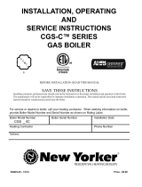
11
C
DE
F
G
HI
Flue Nutlets
Return
Return
Supply
Supply
Supply
Supply
Water Line
Floor Line
29”
38”
AA
A
Chart 3
Boiler
Model
No.
Water Content
in Gallons
Shipping
Weight
Lbs.
A Jacket
Width
L to R
AA
Base &
Battery
Length
CDEFGHI
Steam Water
300
400
500
20
25
30
26
33
40
922
1133
1344
18 3/4
23
27 1/4
16 3/4
21
25 1/4
9 3/8
11 1/2
13 5/8
–
–
–
–
–
–
–
–
–
–
–
–
–
–
–
9 3/8
11 1/2
13 5/8
600
700
800
900
1000
35
40
45
50
55
46
52
58
65
71
1555
1766
1977
2188
2399
31 1/2
35 3/4
40
44 1/4
48
29 1/2
34 3/4
38
42 1/4
46 1/2
9 3/8
9 3/8
11 1/2
11 1/2
13 5/8
12 3/4
14 7/8
17
19 1/8
21 1/4
–
–
–
–
–
–
–
–
–
–
–
–
–
–
–
–
–
–
–
–
9 3/8
11 1/2
11 1/2
13 5/8
13 5/8
1100
1200
1300
1400
1500
60
65
70
75
80
78
84
91
97
104
2610
2821
3032
3243
3454
52 3/4
57
61 1/4
65 1/2
69 3/4
50 3/4
55
59 1/4
63 1/2
67 3/4
9 3/8
1
1 1/2
9 3/8
11 1/2
13 5/8
14 7/8
17
17
19 1/8
21 1/4
17
17
21 1/4
21 1/4
21 1/4
–
–
–
–
–
–
–
–
–
–
–
–
–
–
–
11 1/2
11 1/2
13 5/8
13 5/8
13 5/8
1600
1700
1800
1900
2000
85
90
95
100
105
110
117
123
130
136
3665
3876
4087
4298
4509
74
78 1/4
82 1/2
86 3/4
91
72
76 1/4
80 1/2
84 3/4
89
11 1/2
9 3/8
11 1/2
11 1/2
13 5/8
17
14 7/8
17
19 1/8
21 1/4
17
19 1/8
19 1/8
21 1/4
21 1/4
17
21 1/4
21 1/4
21 1/4
21 1/4
–
–
–
–
–
–
–
–
–
–
11 1/2
13 5/8
13 5/8
13 5/8
13 5/8
2100
2200
2300
2400
2500
110
115
120
125
130
143
149
156
162
169
4720
4931
5142
5353
5564
95 1/4
99 1/2
103 3/4
108
112 1/4
93 1/4
97 1/2
101 3/4
106
110 1/4
9 3/8
11 1/2
11 1/2
11 1/2
13 5/8
12 3/4
17
17
19 1/8
21 1/4
17
17
19 1/8
21 1/4
21 1/4
21 1/4
19 1/8
21 1/4
21 1/4
21 1/4
21 1/4
21 1/4
21 1/4
21 1/4
21 1/4
–
–
–
–
–
13 5/8
13 5/8
13 5/8
13 5/8
13 5/8
2600
2700
2800
2900
3000
135
140
145
150
155
175
182
188
195
201
5775
5986
6197
6408
6619
1
16 1/2
120 3/4
125
129 1/4
133 1/2
114 1/2
118 3/4
123
127 1/4
131 1/2
9 3/8
9 3/8
11 1/2
11 1/2
13 5/8
12 3/4
14 7/8
17
19 1/8
21 1/4
17
19 1/8
19 1/8
21 1/4
21 1/4
21 1/4
21 1/4
21 1/4
21 1/4
21 1/4
21 1/4
21 1/4
21 1/4
21 1/4
21 1/4
21 1/4
21 1/4
21 1/4
21 1/4
21 1/4
13 5/8
13 5/8
13 5/8
13 5/8
13 5/8
BOILER DIMENSIONS
Front View
Left Side View
Top View
ALL SUPPLY AND RETURN
CONNECTIONS ARE 4 INCH

12
Base Assembly
The 300, 400 and 500 boilers are the basic models. The 300
model has (6) burners, the 400 model has (8) burners and
the 500 model has (10) burners. Combinations of the basic
models are used to assemble the 600 through 3000 models.
Refer to Chart 3 for the proper order of assembly. When two
or more bases are used to assemble the boiler, be sure the
tops of the bases are even.
The bases are fastened together with 5/16 cap bolts and
nuts. Insert two bolts in the front posts and two in the rear
posts as shown in Figure 7A . After bases are fastened
together, install the base end panels. These end panels
must be installed before assembling sections Figure 7B.
Important: After bases are assembled check to be sure
they are level.
Section Assembly
The sections may be started from either the left or right end
of the base.
Place the end section on the base with the center-line of the
section directly over the joint of the base end closure. With boilers
having two or more bases, as you progress be sure the parting
line (center-line of section) of the intermediate sections fall on
the junction of the two bases. Figure 8.
Before beginning, clean nipples and nipple ports. Coat
nipples and nipple ports with pipe joint compound
or other good sealant and keep them clean. Figure
9.
Figure #7A
Bolts with nuts in
the front and rear
posts
B
ol
th
e
p
o
s
INSTALLATION – ASSEMBLY
Figure 7A
Figure 7B
g
,
c
Center-line
of section
Base joint
Figure 8
Figure 9
Figure 10

13
Place nipples in ports taking care to seat them squarely to
prevent cocking. Figure 10.
When pulling sections together with tie rods, always insert
tie rods in holes nearest to nipple ports. Move tie rods to
proper location, if necessary, only after sections are fully
pulled together. Oil or lubricate threads, insert tie rods
in lugs with washers under nuts and tighten uniformly
and evenly so that sections are pulled parallel as they go
together. When all sections are pulled up locate tie rods in
alternating pairs of upper and lower holes between adjacent
sections. Figure 11.
Be sure both ends of completed section assembly are
resting evenly on both ends of base.
Apply furnace cement at the joints of the sections front, top
and back. Putty should also be applied where the sections
join the base. Figure 12.
Place necessary plugs and control wells in correct locations.
Plug all other tappings, leaving air vent in top of one of
end sections, and connect water. Fill boiler with water
until it runs out the air vent. Hydrostatically test boiler in
accordance with applicable codes. Check for leaks before
continuing with assembly Drain and remove unnecessary
plugs.
Draft Hood
Draft hood notched
to fi t over sections
J-bolt & nut
attach to front
of hood
Draft hood
clean-out
covers
Apply furnace cement to joints on all sides of boiler.
Attaching Draft Hoods
Attach the draft hoods to the boiler sections after
applying boiler putty to the top of the boiler sections
where the hoods and sections meet. Use j-bolts to
attach the fronts of the draft hoods to slots in the
section fl anges. Figure 13.
INSTALLATION – ASSEMBLY
Figure 13
Figure 11
Figure 12

14
Position top/front intermediate panel so back edge of top
4.
hangs on adjustable clips on front of draft hood(s); left
edge hangs on bracket on left upper jacket end panel;
and right edge with integral bracket hangs on tie rod(s).
Figure 17.
Attach top/front intermediate panel to lower base
5.
brackets through four slotted holes in panel. Use (4)
#10 x ½” screws. Figure 18.
On multiple base boilers, each additional top/front
6.
intermediate panel attaches in same way (working your
way from left to right). Figure 19.
Adjustable Clips
Bracket
R
R
ight
ight
E
E
dge
dge
I
I
ntegral
ntegral
B
B
racket
racket
Front
Front
J
J
acket
acket
P
P
anel
anel
Installed
Installed
Front
Front
J
J
acket
acket
P
P
anel
anel
Installing Boiler Jacket Panels
NOTE: Jacket assembly must start at the left side of boiler.
Attach lower jacket end panel (left) to two Z-bars on
1.
base end closures through two slotted holes on bottom
of jacket end panel. Use (2) #10 x ½” screws. Figure
14.
Attach middle jacket end panel (left) to lower jacket
2.
end panel with middle laying over lower and lining up
holes. Use (5) #10 x ½” screws. Figure 15.
Attach upper jacket end panel (left) to middle jacket
3.
end panel with upper behind middle and lining up holes.
Use (6) #10 x ½” screws. Attach upper jacket end
panel to rear side of draft hood. Use (1) #8 x ¾” screw.
Figure 16.
INSTALLATION – ASSEMBLY
Figure 15
Figure 14
Figure 16
Figure 17

15
Installing Boiler Jacket Panels - Continued
Attach upper jacket end panel (right) so left edge hangs
7.
on bracket on top/front intermediate panel. Attach up-
per jacket end panel to rear side of draft hood. Use (1)
#8 x ¾” screw. Figure 20.
Attach middle jacket end panel (right) to upper jacket
8.
end panel with middle laying over upper and lining up
holes. Use (6) #10 x ½” screws. Figure 21.
Attach lower jacket end panel (right) to middle jacket
9.
end panel with lower behind middle and lining up holes.
Use (5) #10 x ½” screws. Attach lower jacket end
panel to two Z-bars on base end closures through two
slotted holes on bottom of jacket end panel. Use (2)
#10 x ½” screws. Figure 21B.
Position top of rear jacket panel(s) to draft hood baffl e
10.
fl ange and secure with (2) #10 x ½” screws. Secure
bottom of rear jacket panel(s) to bracket(s) on boiler
base using (2) #10 x ½” screws. Figure 22.
INSTALLATION – ASSEMBLY
Figure 19
Figure 18
Figure 21A
Figure 20

16
Installing Boiler Jacket Panels - Continued
Attach burner door knobs with #8-32 x ¼” screws and
11.
#8-32 hex nuts. Slide bottom of lower access door(s)
in slots on top of manifold brackets. Figure 23.
Position control access jacket panel(s) so tabs slide into
12.
slots on top/front intermediate jacket panel(s). Attach
control access jacket panel to top/front intermediate
jacket. Use (2) #10 x ½” screws. Figure 24.
INSTALLATION – ASSEMBLY
Figure 22
Figure 21B
NOTE: The attachment of the control access jacket
panels can wait until the controls have been mounted
to the top/front intermediate jacket panels.
Figure 24
Figure 23
Lighting Instruction Plates are provided with each
13.
boiler base. Each boiler base also includes data plate
indicating required gas type, fi ring rate, and gas
pressure for that base. These plates are located on
Jacket Top/Front Panels. Boilers also have rating plate
showing total Input and Output Ratings. This rating
plate is shipped in AC Carton and is to be mounted on
side Jacket End Panel by installing contractor.
Attach Local Code Label
14.
(not provided by
manufacturer.)

17
Control Mounting And Installation
NOTE: Electrical controls (j-box, transformer, etc. can
be mounted on either left or right jacket end panel.
Subsequently, boiler safeties (LWCO, etc.) and their
respective piping must be mounted on opposite end of
boiler.
Attach j-box assembly to jacket end panel aligning with
1.
holes in end panel. Use (4) #10 x ½” screws. Figure
25A.
Position harness and plug from j-box through opening
2.
in jacket end panel. Figure 25B.
Boilers with four through six bases, require transformer
3.
mounted externally to j-box assembly. Attach
transformer and bracket assembly to jacket end panel by
using #10 x ½” screws; (3) along top of bracket and (2)
along lower edge of bracket. Figure 26A. Remove cover
(2 screws) from J-box, then remove knockout (left or
right side). Connect plug of harness from transformer to
plug on j-box.
Figure 26B.
Orient harness of control panel assembly so correct
4.
(female) plug is toward j-box and will connect to
j-box harness. Figure 27A. Secure harness to control
panel with zip-ties and #10 x ½” screws. Figure 27A.
Connect plugs on harnesses. Figure 27B.
Attach control panel to intermediate jacket panel
5.
aligning with holes. Use (4) #10 x ½” screws. Connect
plugs on control panel to j-box. Figure 28.
On multiple base boilers, mount remaining control
6.
panels to intermediate jacket panels following steps 4
& 5.
On each base, connect gas valve harness and pilot
7.
spark wire to control. Figures 29A & 29B.
INSTALLATION – ASSEMBLY
Figure 25B
Figure 25A
Figure 26A
Figure 26B

18
Figure #27A
INSTALLATION – ASSEMBLY
Control Mounting And Installation
Figure 27A
Figure 29A
Figure 27B
Figure 28
Figure 29B

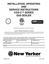
19
Illustration shows the end section and the various tap-
pings provided. Tappings are the same in both right
and left end sections.
OPENING SIZE STEAM WATER
A 4”
Supply and Return
Supply and
Return
B ½”
Primary LWCO and
Gauge Glass Set
Plugged
C ¾” Drain, Left End
Drain, Left
End
C ¾” Drain, Right End
Drain, Right
End
D ½” Plugged
Limit Con-
trol
E 1” Accessories Accessories
*F 1” Safety Valve
Safety Relief
Valve
G ¾”
Plugged or Electronic
(Probe Type) LWCO
Plugged
*If opening F is to be used for something other than
the Safety Valve or Safety Relief Valve, or the Safety/
Relief valve is larger than 1”, the Safety/Relief Valve
must be installed in the Header Piping as near the
boiler as possible
A
B
A
B
C
D
E
F
G
BOILER TRIM
Following controls are supplied as standard equipment.
Details of their function and operation will be found in
section on Controls and Adjustments.
WATER TRIM
1. Water temperature high limit control
2. Combination temperature - pressure gauge
3. Safety relief valve (30 psi)
WATER TRIM ASSEMBLY
Locate water trim controls per chart and illustration
above.
STEAM TRIM
Low Water Cut-Off (mounted externally) with blow-off
1.
valve
High Pressure Limit Control
2.
Pressure Gauge
3.
Water Gauge Glass Set
4.
Siphon Loop
5.
Safety Valve
6.
(15 psi..)
NOTE:
No shutoff of any description shall be placed between
the pressure relief valve and the boiler, or on discharge
pipes between such safety valves and the atmosphere.
Installation of the pressure relief valve shall conform
to the requirements of the ANSI/ASME Boiler and
Pressure Vessel Code, Section IV.
STEAM TRIM ASSEMBLY
Assemble Steam Trim, Low Water Cut-Off, High
Pressure Limit Control, Pressure Gauge, Water Gauge
Glass Set and Siphon Loop, as shown in Figures
30. See Illustration and Chart above for location of
controls.
Figure #30
WATER LEVEL
29” TO FLOOR
TAPPINGS
Figure 29
Figure 30

20
BOILERS USED WITH REFRIGERATION SYSTEM
When the boiler is installed in connection with a
refrigeration system, it must be piped so that the
chilled medium is piped in parallel with the heating
boiler with appropriate valves to prevent the chilled
medium from entering the heating system. An example
of such piping is shown in Figure 31, Valve A and B
open for heating, closed for cooling. Valves C and D
closed for heating, open for cooling.
When hot water boilers are connected to heating
coils located in air handling units where they may be
exposed to refrigerated air circulation on the boiler
piping, the boiler piping system shall be equipped
with fl ow control valves or other automatic means to
prevent gravity circulation of the boiler water during
the cooling cycle.
WATER BOILER PIPING Figure 32
Supply and return connections to the hot water boiler
should be located so that the water will thoroughly
circulate throughout the entire boiler. Each installation
has a preferred piping arrangement according to the
requirements of the particular system and choice of
arrangements and sizes of headers should be decided
upon by the installer’s heating engineer or with standard
engineering practice. When using only one supply and
one return connection, return must be connected at
opposite end of boiler from fl ow connection, on all
boilers 600,000 Btu/hr input and larger.
HIGH LIMIT
The immersion well for the high limit control must be
mounted at fl ow outlet of boiler. This may be either
right or left hand. The temperature and pressure gages
should be mounted at the outlet as well, and may be
the opposite and of the high limit control.
FLOW RATE GPM PIPE SIZE
35 - 50 2½”
51 - 76
3”
77 - 131 4”
132 - 205 5”
206 - 300 6”
PIPE SIZING
Piping connection sizes are important to control proper
water velocity at the inlet and outlet connections to
the water boiler. It is recommended that the following
pipe sizes be used for fl ow rates shown and that the
boiler being headered to tappings at both ends, where
one pipe connection will not be adequate to hold water
velocities below 3.33 feet per second.
BOILER PIPING
Figure 31
Figure 32
/