Page is loading ...


2
OMEGAnet
SM
On-Line Service
http://www.omega.com
Internet e-mail
info@omega.com
Servicing North America:
USA:
ISO 9001 Certified
One Omega Drive, Box 4047
Stamford, CT 06907-0047
Tel: (203) 359-1660
e-mail: info@omega.com
FAX: (203) 359-7700
Canada:
976 Bergar
Laval (Quebec) H7L 5A1
Tel: (514) 856-6928
e-mail: info@omega.ca
FAX: (514) 856-6886
For immediate technical or application assistance:
Usa and Canada:
Sales Service: 1-800-826-6342 / 1-800-TC-OMEGA
SM
Customer Service: 1-800-622-2378 / 1-800-622-BEST
SM
Engineering Service: 1-800-872-9436 / 1-800-USA-WHEN
SM
TELEX: 996404 EASYLINK: 62968934 CABLE: OMEGA
Mexico and
Latin America:
Tel: (95) 800-826-6342
En Español: (95) 203-359-7803
e-mail: espanol@omega.com
FAX: (95) 203-359-7807
Servicing Europe:
Benelux:
Postbus 8034, 1180 LA Amstelveen, The Netherlands
Tel: (31) 20 6418405
Toll Free in Benelux: 0800 0993344
e-mail: nl@omega.com
FAX: (31) 20 6434643
Czech Republic:
ul. Rude armady 1868, 733 01 Karvina-Hranice, Czech Republic
Tel: 420 (69) 6311899
Toll free: 0800-1-66342
e-mail: [email protected]m
FAX: 420 (69) 6311114
France:
9, rue Denis Papin, 78190 Trappes
Tel: (33) 130-621-400
Toll Free in France: 0800-4-06342
e-mail: france@omega.com
FAX: (33) 130-699-120
Germany/Austria:
Daimlerstrasse 26, D-75392 Deckenpfronn, Germany
Tel: 49 (07056) 3017
Toll Free in Germany: 0130 11 21 66
e-mail: info@omega.de
FAX: 49 (07056) 8540
United Kingdom:
ISO 9002 Certified
One Omega Drive , River Bend Technology Centre
Northbank, Irlam, Manchester
M44 5EX, England
Tel: 44 (161) 777-6611
Toll Free in United Kingdom: 0800-488-488
e-mail: info@omega.co.uk
FAX: 44 (161) 777-6622
It is the policy of OMEGA to comply with all worldwide safety and EMC/EMI regulations that apply. OMEGA is constantly
pursuing certification of its products to the European New Approach Directives. OMEGA will add the CE mark to every
appropriate device upon certification.
The information contained in this document is believed to be corrected but OMEGA Engineering Inc. accepts no liability for any errors it
contains, and reserves the right to alter specifications without notice.
WARNING
: These products are not designed for use in, and should not be used for, patient connected applications.

3
INTRODUCTORY NOTE
This user’s guide contains operating instructions, as well as a description of the principles of operation, of the
OSP Series portable IR thermometers.
This information covers all models of the instrument, including the basic equipment and its options and
accessories.
This manual is a complete “USER GUIDE”, providing step-by-step instructions to operate the instrument in
each of its designed functions.
OMEGA has used care and effort in preparing this guide and believes the information in this publication to be
accurate. OMEGA products are subjected to continuous improvement, in order to pursue the technological
leadership; these improvements could require changes to the information of this guide.
OMEGA reserves the right to change such information without notice.
No part of this document may be stored in a retrieval system, or transmitted in any form, electronic or
mechanical, without prior written permission of OMEGA Engineering Inc.
OSP portable IR thermometers use sophisticated analogic and digital technologies. Any maintenance
operation must be carried out by qualified personnel
ONLY
. We recommend you contact our technicians for
any support requirements.
When Ni-MH rechargeable batteries are ordered, the unit can be powered also by 115V
±
10% 50/60Hz line
supply using the special power supply module provided.
OSP is fully tested in conformity with the directive n°89/336/CEE Electromagnetic Compatibility. OMEGA
shall not be liable in any event, for technical or publishing error or omissions, or for any incidental and
consequential damages, in connection with, or arising out of the use of this guide.
IMPORTANT :
B
EFORE USING THE
OSP
FOR THE FIRST TIME
,
GO OVER THESE OPERATING INSTRUCTIONS CAREFULLY AND KEEP
THEM AVAIABLE FOR FUTURE REFERENCE
.
Danger and Certification Labels
Labels Location – refer to section 8.2
Warnings and Cautions – refer to section 8.1

4
TABLE OF CONTENTS
1 GENERAL DESCRIPTION...................................................................................................................6
1.1 Instrument codes..............................................................................................................................................7
1.2 Specifications ...................................................................................................................................................8
2 GENERAL FEATURES........................................................................................................................9
2.1 General.............................................................................................................................................................9
2.2 Optical System .................................................................................................................................................9
2.3 Target pinpointing.............................................................................................................................................9
2.4 Taking measurements ......................................................................................................................................9
2.5 Keyboard ........................................................................................................................................................10
2.6 Display............................................................................................................................................................10
2.7 Digital Interface...............................................................................................................................................10
2.8 Self calibration................................................................................................................................................10
2.9 Thermocouple Input........................................................................................................................................10
2.10 Analog Output ................................................................................................................................................10
2.11 Logging Mode.................................................................................................................................................11
2.12 Calculated Measurements..............................................................................................................................11
2.13 Case ...............................................................................................................................................................11
2.14 Logging Data Manager...................................................................................................................................11
3 PHYSICAL DESCRIPTION ................................................................................................................12
4 FUNCTIONAL DESCRIPTION...........................................................................................................13
4.1 Power supply..................................................................................................................................................13
4.2 Keyboard ........................................................................................................................................................13
4.3 Microcontroller................................................................................................................................................14
4.4 Firmware ........................................................................................................................................................14
4.5 Display............................................................................................................................................................14
4.6 Battery charger...............................................................................................................................................14
4.7 Digital interface...............................................................................................................................................14
5 UNPACKING ......................................................................................................................................15
6 PRE-OPERATIONAL CHECK ...........................................................................................................16
7 POWER SUPPLY...............................................................................................................................17
7.1 Rechargeable batteries ..................................................................................................................................17
7.1.1 How to maximize the life span of the battery .............................................................................................17
7.2 Power supply with alkaline batteries...............................................................................................................17
7.3 Power supply from main line AC.....................................................................................................................17
8 WARNINGS & CAUTIONS.................................................................................................................18
8.1 Laser Sight .....................................................................................................................................................18
8.2 Analogue input................................................................................................................................................18
8.3 Danger and Certification Labels .....................................................................................................................18
9 OPERATIONS ....................................................................................................................................20
9.1 Quick Start......................................................................................................................................................20
9.2 How to Operate the instrument.......................................................................................................................20
9.3 Hold ................................................................................................................................................................21
9.4 Laser sighting .................................................................................................................................................21
9.5 Unstable temperature measurement ..............................................................................................................22
9.6 Alarm settings.................................................................................................................................................23
9.7 Thermocouple input........................................................................................................................................24
9.8 Minimum, maximum, average and difference indication.................................................................................25
9.9 Automatic Emissivity Setting ..........................................................................................................................26
10 CONFIGURATION..............................................................................................................................27
10.1 Technical Unit selection..................................................................................................................................27
10.2 Thermocouple input enabled ..........................................................................................................................27
10.3 Temperature Scale selection..........................................................................................................................27
10.4 Date & Real Time clock setting ......................................................................................................................28
10.5 Acquisition settings.........................................................................................................................................28
10.6 Buzzer On/Off.................................................................................................................................................29
10.7 OSP 500/800 decimal point selection.............................................................................................................29
10.8 Ambient Temperature Compensation (TAM)..................................................................................................29
10.9 Firmware revision number..............................................................................................................................30
10.10 Instrument serial number...........................................................................................................................30
10.11 Battery level of charge ...............................................................................................................................31

5
11 DATA ACQUISITION OPERATIVE MODE........................................................................................32
11.1 How to operate in data acquisition mode........................................................................................................32
11.2 Recall stored data...........................................................................................................................................34
12 LOGGING DATA MANAGER ............................................................................................................35
12.1 Installation ......................................................................................................................................................35
12.2 Program Architecture.................................................................................................................................35
12.2.1 Toolbars.....................................................................................................................................................37
12.3 Quick starting .................................................................................................................................................38
13 OPTIONS & ACCESSORIES.............................................................................................................42
13.1 Printer operations ...........................................................................................................................................42
13.2 Sighting telescope system..............................................................................................................................42
13.3 Red Point pinpointing system .........................................................................................................................43
14 APPLICATION NOTES ......................................................................................................................45
14.1 Infrared energy ...............................................................................................................................................45
14.2 Applications ....................................................................................................................................................45
14.3 Emissivity...................................................................................................................................................45
14.4 Reflected energy compensation .....................................................................................................................45
15 DIGITAL INTERFACE........................................................................................................................46
15.1 Digital output wiring practice...........................................................................................................................46
15.2 TTL to RS 232 adapter...................................................................................................................................46
15.3 Communication protocol.................................................................................................................................47
15.3.1 Computer data request from OSP to PC ...................................................................................................47
15.3.2 Computer data setting from PC to OSP.....................................................................................................49
15.3.3 Communication programs..........................................................................................................................50
16 MAINTENANCE..................................................................................................................................52
16.1 Faulty operating conditions.............................................................................................................................52
16.2 Storage...........................................................................................................................................................52
APPENDIX.......................................................................................................................................................53
A1 How to determine an object emissivity ...........................................................................................................54
A1.1 Typical Emissivity Values ..........................................................................................................................54
A1.2 Metals - Typical Emissivity Values.............................................................................................................55
A1.3 Non-metals - Typical Emissivity Values .....................................................................................................56

6
1 GENERAL DESCRIPTION
Portable infrared thermometers measure surface temperature without touching the surface. They collect the infrared
energy radiated by a target and compute its surface temperature.
OMEGA OSP Series
are portable infrared temperature devices designed to ease maintenance operations. They also
enable the monitoring of operating temperatures of mechanical and electrical plants or production equipment without
removing the equipment from the service.
Any temperature variation noticeable in whatever kind of system device should show critical overheating conditions
which may cause malfunctioning to the device itself.
They are also useful to measure product temperatures during manufacturing, to spot problems before they reduce quality
or cause production downtime.
Their principle of operation is very simple, the instrument determines the temperature of an object by measuring the
amount of radiant energy emitted by it.
The detector, installed on each
OSP
unit, responds by producing a voltage signal which is directly proportional to the
amount of energy received, and therefore is a function of the temperature of the target. By sampling and manipulating
the output of the detector, the microcontroller-based electronics can display the temperature and the related computed
values such as maximum, minimum, average, and difference temperatures seen during the measurement. The same
information can also be stored and processed via Personal Computer (using electronic spreadsheets e.g. Lotus, Excel,
Paradox, etc.). The displayed value can be printed out directly into an external printer supplied on request.
Thanks to its advanced optical system and electronics,
OSP
can be very useful for objects 5mm and larger and can
operate in critical ambient conditions.
To take measurements by using
OSP
thermometers just pull the trigger and then point at the target to be measured. The
trigger can be locked on if desired. For more distant targets, hold the unit at arm length and use the sighting notch and
post to aim. This will give a parallel and offset sighting. Also Laser beam is available for sighting target.
Temperature information as well as auxiliary parameter pieces of information are shown on the high contrast liquid
crystal display (LCD).
The case, made in shock-resistant ABS + polycarbonate, is ergonomically designed for an easy practical use.
The instrument is powered by a group of four alkaline or Ni-MH rechargeable batteries (AA type); an external battery
charger module is supplied as a standard accessory.
OSP
portable IR thermometers have been developed using the most advanced microcontroller technique to provide high
accuracy on extended ranges and a powerful operating flexibility.
The calibration uses computerized procedures and the relevant calibration data are memory stored to ensure high
accuracy.
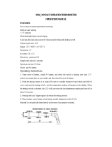
General features
OSP
non contact infrared thermometers are designed to simplify temperature measurements at distance from a target
and to identify hot spots, which normally means anomalous operative conditions avoiding costly downtime or processing
problems that lead to rejected products. There is no need to focus as required by photographic equipment. Accurate
measurements result if
OSP
field of view diameter is smaller than the target.
Innovative design
This new line of portable instruments represents the most versatile and powerful infrared temperature system.
The most appropriate aiming system at the application can be selected with a twin laser pinpointing or with a combination
of twin lasers and telescope or red point for true universal applications.
An on board data logger is available to store up to 500 data points, an analogue output can drive directly a recorder or a
controller, The real-time temperature can be displayed together with the Maximum, Minimum, Difference and Average
values.
Each model incorporates the following :
• high quality optical system
• high sensitivity infrared radiation detector
• auxiliary input for thermocouple type K and S
• microcontroller circuit
• high contrast LCD display with backlight device
• extended life traditional microswitch keyboard
• four alkaline or rechargeable Ni-MH type AA batteries
• external module for battery charge and/or line operation
• analogue output
• digital interface

7
1.1 Instrument codes
To Order
Model No. Temperature
Range
Spectral
Response
Target Spot Size
@ Distance **
D/S Optical Ratio
OSP500-(*)
–30 °C to +930 °C
-20°F to +1706°F
8 to 14
µ
m
10mm @ 600mm
0.39 @ 24”
60:1
OSP800-(*)
–30 °C to +930 °C
-20°F to +1610°F
8 to 14
µ
m
10mm @ 600mm
0.39 @ 24”
60:1
OSP1000-(*)
–30 °C to +1000 °C
-20°F to +1830°F
8 to 14
µ
m
10mm @ 1000mm
0.39 @ 39.4”
100:1
OSP1300-(*)
+300 °C to +1300 °C
+570°F to 2370°F
1.6
µ
m
6mm @ 1000mm
0.236 @ 39.4”
167:1
OSP1600-(*)
+600 °C to +1600 °C
+1120°F to 2900°F
1
µ
m
5mm @ 1000mm
0.20 @ 39.4”
200:1
OSP2000-(*)
+600 °C to +2000 °C
+1120°F to +3630°F
1
µ
m
5mm @ 1000mm
0.20 @ 39.4”
200:1
* Insert suffix codes B and C and D from options chart above
** See Target spot size diagram
Note
: all accessories and options must be specified at time of order.
Each Pyrometer supplied with
: Alkaline battery, laser, operators manual, and calibration report
Options
Suffix Code Description OSP500 OSP800 OSP1000 OSP1300 OSP1600 OSP2000
-B0
Alkaline battery std std std std std std
-B1
Rechargeable Battery Opt Opt Opt Opt Opt Opt
-C1
Single Laser Std No No No No No
-C2
Twin crossed Lasers No Std Std Std Std Std
-C3
Twin normal Lasers No Std Std std Std Std
-C4
Single Laser with Circle Std No No No No No
-D1
Vinyl Case Std Std No std Std No
-D2
Aluminum Case Opt Opt Std Opt Opt Std
-D3
Memory+Software+RS232 Cable Opt Opt Std Opt Opt Std
-D6
Sighting telescope No No Opt Opt Opt Opt
-D7
Red Point No No No Opt Opt Opt
-D8
Alarms Std Std Std std std Std
-D9
Analog Output Opt Std std std std Std
-DA
Aux Input for Tc K & S Opt std std std std Std
Report of Calibration std std std std std Std
No = Not available Std = Standard at no extra cost
Single laser
: General application, target center
Single laser with circle
: General application, target center plus target dimension with circle (short distance)
Twin crossed lasers
: General application, target dimension
Twin normal lasers
(parallel): Long distance application over 5m (16’)
Red Point
: High temperature over 1250°C 1x
Sighting Telescope
: High temperature over 1250°C 2x tele
Software
(D3): Includes memory up to 500 values. You can divide them by Tag (20 different). Each value includes
temperature value and date&time (built in real time clock). Tag name with 7 characters on instrument
display. Datalogging manual or automatic with sampling time from 1 to 999 sec. Windows 95 software to
download data to PC and cable. You can view, save, print, export to Excel and graph data.
U.S. and international Patents and Patents Pending.

8
1.2 Specifications
Target dimensions at different distances
Nominal target diameter at 95% energy
•
Temperature measuring ranges:
-30 to 2000°C (-22 to 3632°F)
•
Thermocouple measuring ranges:
type K :
-100°C to +1370°C (-148 to 2500°F) 0.1°C resolution
type S :
0°C to +1760°C (-32 to 3200°F) 0.1°C resolution
•
Spectral response:
OSP 500, 800 & 1000 :
8 - 14 µm
OSP 1300 :
1.6 µm
OSP 1600 & 2000
0.9 µm
•
Accuracy:
OSP 500, 800 & 1000:
±(1% of the reading +1°C/2°F)
OSP 1300, 1600 & 2000:
±(0.5% of the reading +1°C/2°F)
•
Repeatability IR:
OSP 500, P800 & P1000 :
±0.5% of the reading
OSP 1300, P1600 & P2000:
±0.25% of the reading
•
Temperature stability IR:
for the band exceeding +18°C to +28°C:
±0.01% of f.s./°C
•
Display:
High contrast custom LCD with backlight device
•
Display resolution:
1°C / °F / K (0.1°C/0.1°F in AVG mode up to 200°C)
•
Alarms:
Acoustic and visible
•
Measurement sampling time:
<300 ms
•
Emissivity:
Adjustable from 0.10 to 1.00 in 0.01 steps
•
Analog output:
1 mV/ °C/ °F/ K
•
Digital interface:
full bi-directional TTL level port
Optional TTL to RS232 adapter
•
Calculated functions:
Hold, average, max, min,
∆
T
•
Data memory:
500 input data structured by tag
•
Calibration:
self learning technique with automatic procedure
•
Laser:
Wavelength
: 650nm
Maximum optical power
: <1mW
FDA Classification
: Class II, Complies with 21CFR Chapter 1,
Subchapter J
Safety classification
: Class 2
Beam diameter
: 3mm
Beam divergence
: <0.5mrad
Laser indicator
: asterisk on display
•
Power supply:
alkaline or rechargeable type AA battery
•
Battery life:
16 h (with backlight off)
•
Battery low level of charge:
symbol on the LCD display
•
Line operation:
100, 115, 230 Vac through the external charger
•
Charger transformer insulation:
2500 V
•
Battery recharging time:
8 h at 90% (instrument switched off)
•
Operating environment temperature range:
from -10°C to +55°C (-14 to 131°F)
•
Storage temperature range:
from -30 °C to +60 °C (-22 to 140°F) without battery
•
Case:
Injection moulded ABS+ policarbonate
•
Dimensions:
200 x 180 x 80 mm (7.87 x 7.09 x 3.15”)
•
Weights:
net 0.8 kg (1.76 lb); gross 1.5 kg (3.3 lb)

9
2 GENERAL FEATURES
2.1 General
Temperature measurements of a liquid or gaseous compound have been successfully made with thermoelectric or
expansion thermometers thanks to the good thermal exchange of the sensor with the fluid.
With solid bodies a good thermal exchange is difficult to be obtained and an additional measuring error should be
considered.
A direct contact measurement is impractical when the object being measured is moving, it cannot be touched with a
thermoelectric sensor because of electrical hazard or of other reasons.
A non-contact IR temperature measurement is the best solution to the above application problems.
Also other applications benefit because non-contact thermometers do not add or remove heat or disturb the process in
any way, and there is no wear and tare on the instrument.
2.2 Optical System
The optical system is equipped with a main objective to focus the infrared energy into the infrared detector through a
single lens, a filter and a field stop which defines the visual cone and therefore the target dimensions.
As the detector is placed in the focal point of the measurement portion of the optical system no focusing operations are
required.
A secondary, but extremely important objective, is the correct pinpointing of the target as described below.
The optical diagrams are shown in the previous specification section.
2.3 Target pinpointing
A correct aiming at the target is an important factor of a non-contact thermometer. The immediate evaluation of the
smallest measurable target area is also a positive key factor in many applications.
The following types of pinpointing are available :
• A “V” groove on the up side of the instrument can be used stretching the arm.
• Twin laser pointers to define, at distance, the measurable target dimensions. Two versions are available with crossing
or parallel twin lasers. The twin crossed lasers are suggested for target distance upper than 5 meters.
• Combination of twin lasers and direct telescope viewing for universal applications mainly required for a high distance
targets (more than 10 meters) and high temperature targets (more than 1000 °C) where laser spots are not visible .
• Combination of twin lasers and a red point pinpointing for universal applications mainly required for high temperature
target where laser spots are not visible
With a laser pinpointing the operation of the instrument is extremely simplified. You simply aim at the target and read the
temperature.
The installation procedures for telescope and red point pinpointing, please refers to the dedicated chapters.
2.4 Taking measurements
OSP
portable thermometers are accurate, rugged and compact.
Its modern and practical design allows an easy handling and aiming, either at arm length or using a tripod mount, to
obtain current temperature value, average, minimum, maximum and difference temperature measurement values.
Its analogue to digital outputs allows a continuous documentation on a continuous trace recorder or on a serial printer.
Using the keyboard it is also possible to enable the instrument to measure one of the computed values in addition to the
actual temperature value measurement:
MAX maximum temperature recorded during current measurement
MIN minimum temperature recorded during current measurement
DIF difference between MAX and MlN
AVG average temperature for entire measurement
Tamb ambient temperature

10
2.5 Keyboard
Traditional metal-click switches, with a working life of one million operations, are used to enter the operator’s instructions.
The contact closure of the keyboard keys is acknowledged, as a coded signal, directly by the microcontroller.
2.6 Display
The high contrast customised alphanumeric LCD display indicates the measured temperature value.
It is also used for operators’ messages, instrument configuration set-up, special operative modes, etc.
It is equipped with a backlight device to allow easy readings even in poor light conditions.
2.7 Digital Interface
A digital interface with TTL logic levels is available for communication with external units. A serial data port provides
communication capability at a logic level of 0-5 V (four wires: Tx, Rx, GND, Vcc).
A special software set enables the transfer of all the recorded data on a Personal Computer for further statistical
analysis.
2.8 Self calibration
The hardware-firmware design allows the automatic calibration of the instrument. The calibration procedure is protected
by a security code.
2.9 Thermocouple Input
To extend the operative capability the instrument is equipped with an auxiliary input for thermocouple.
This feature, when used with a calibrated thermocouple, can be used to obtain accurate temperature measurements
eliminating the problems of emissivity and the interfering light.
The thermocouple can be used to obtain an accurate temperature reading of the target material and then these data are
used to determine the compensation value for the actual emissivity, including the interfering light, within a range from
0.10 to 1.00.
2.10 Analog Output
An analog output (1 mV/°C/°F/K) is available to drive an external analog input device (eg. a potentiometric or hybrid
recorder) for long term trend profiling and tests.

11
In this case the instrument can be powered directly from mains using the external power supply module supplied with the
thermometer.
2.11 Logging Mode
The instrument can be equipped with an internal memory to store up to 500 input data.
Two types of data acquisitions can be selected by the user.
Continuous acquisition
The operator can select the interval time between each acquisition and store progressively the input data in the Tag file
or can manually, step by step, give the acquisition instruction.
Acquisition by dedicated tag
Standard Agencies and Quality Auditors require the collection, organization and availability of traceability documents.
A supporting software is available to transfer a selection of plant inspections from a PC to the internal memory of the
instrument in order to simplify field check and select the appropriate tag number.
Dedicated input data are memory stored and downloaded into a PC to document the inspection activity.
Data can be saved on disks, viewed and printed in a numeric or graphic mode.
2.12 Calculated Measurements
For the measurement of unstable input signals by a progressive averaging with a programmable average weight. In
addition the operator can select average, minimum, maximum, Tmax -Tmin, differential.
2.13 Case
The case of the instrument is ergonomically designed for an easy hand held operation and transport.
The body is injection molded, shock-resistant, flame proof ABS+ polycarbonate.
A vinyl case with shoulder strap and an aluminum case for instrument + printer + accessories are available on request.
2.14 Logging Data Manager
LogMan software allows the OSP series users to set and prepare the infrared thermometers to acquire the data
organized by ‘Tag’. This software also allows to download data from Instrument on document (table) with date, time and
value. You can view table, save table, print table, export table in excel-txt-html and obtain graph. You can also manage
data coping, moving on other tables.

12
3 PHYSICAL DESCRIPTION
OSP
portable IR thermometers consist of a rugged, compact and self-extinguishing case ergonomically designed for an
easy practical use.
The instrument can be supplied either with a vinyl protective case with shoulder strap or with an aluminum case to
assure better protection against mechanical knocks or scratches.
The battery container is located on the lower part of the handle, and is accessible through a cover fastened by a metal
screw.

13
4 FUNCTIONAL DESCRIPTION
OSP series infrared portable thermometers block diagram is shown below:
Measuring
ob
j
ect
Emitted IR energy
Optical system
Filter
Detector
Amplifier
A/D
converter
Micro-
controller
LCD
display
Tc
Auxiliary
input
Keyboard Digital
interface
Analog
Output
•
Optical system
•
Filter
•
Detector
•
Amplifier
•
A/D converter
•
Microcontroller
•
LCD display
•
Digital interface
•
Keyboard
•
Tc auxiliary input (optional)
•
Analog output (optional)
The radiated infrared energy is focused by the optical system on an infrared detector sensitive to the required spectral
band. The infrared detector generates a signal proportional to the energy received corresponding to the temperature and
emissivity of the target. See Appendix A for emissivity values.
The output signal of the sensor is then conditioned, converted from analog to digital and transmitted to the
microcontroller. The procedures used to process all the operating functions as well as measure and calculation routines
are stored into the microcontroller memory. Any operator’s instruction, through the trigger and the keyboard is directly
recognized, as a coded signal, by the microcontroller. The actual temperature value and the active operative mode are
indicated on the LCD display.
4.1 Power supply
The instrument is powered, if not otherwise specified with the order, by four internal alkaline batteries or rechargeable Ni-
MH type AA (nominal voltage 1.25 V) that can be recharged through an external charger module supplied as a standard
accessory.
4.2 Keyboard
The operative keyboard is designed with a traditional single microswitch per button for long life and high reliability. The
contact closure of the keys is acknowledged as a coded signal by the microprocessor that recognizes the operator’s
instructions.

14
4.3 Microcontroller
The microcontroller handles all the logic functions of the instrument, performs the linearization for non linear transducers,
compensates for the reference junction temperature, drives the digital display and acknowledges all the operator’s
instructions.
The core of the circuit is a single-chip microcomputer that utilizes HCMOS technology to provide the low power
characteristics and high noise immunity of CMOS plus the high speed operation of HMOS.
The microcomputer provides highly sophisticated, on- chip peripheral functions including: 256 bytes of static RAM, an 8
channel analog to digital (A/D) converter (used to read the Rj value, the setting of the input comparator, the battery
package voltage and the value of the auxiliary input), a serial communication interface (SCI) subsystem, and a serial
peripheral interface (SPI) subsystem.
The microprocessor works with an 8-bit communication bus to EPROM and EEPROM memories and is interfaced with a
decoder, a latch of address and an inverter-driver.
4.4 Firmware
The operating system firmware handles all the logic instructions to the internal peripheral circuits and performs the
computation of the linearization equations.
The application system firmware is resident on the non-volatile memory (EEPROM) of the microprocessor chip.
It is used to store the installation parameters (autocalibration data, program data, etc.)
4.5 Display
The custom display, placed on an auxiliary board, uses high contrast LCD technologies (STN liquid).
OSP
thermometers
are standard equipped with a backlight device for easy readings in poor light conditions.
4.6 Battery charger
The auxiliary module, supplied as a standard accessory, allows operations from 115 Vac 50/60 Hz.
OSP
, if needed, can
be operated directly from a line source through the charger.
The plastic case of the battery charger incorporates the line voltage plug and a cable with a connector for
interconnections to the instrument.
The charger circuit is designed with an insulating transformer and a voltage stabilizer circuit. The step-down transformer
reduces the power line 115 Vac to a value of 10 Vac. The above voltage is full wave rectified , filtered and stabilized. The
output voltage of 5.6 Vdc is the ideal value to recharge the internal Ni-MH batteries
4.7 Digital interface
The digital interface circuit is essentially based on the serial communication interface subsystem (SCI) on the chip of the
microprocessor at 0 / +5V level. Adapters to convert TTL to RS 232 voltage levels are available from OMEGA.

15
5 UNPACKING
Remove the instrument from its packing case and remove any shipping ties, clamps, or packing materials.
Carefully follow any instruction given on any attached tags.
Inspect the instrument from scratches, dents, damages to case corners etc. which may have occurred during shipment.
If any mechanical damage is noted, report the damage to the shipping carrier and then notify OMEGA directly or its
nearest agent, and retain the damaged packaging for inspections.
A label indicates the serial number of the instrument.
Refer to this number for any inquiry for service, spare parts supply or application and technical support requirements.
OMEGA
will keep a data base with all information regarding your instrument.

16
6 PRE-OPERATIONAL CHECK
OSP series
portable thermometers are powered either by four alkaline or by Ni-MH rechargeable batteries (optional).
The external battery charger, supplied as a standard , is set for 115Vac power source.
Before using the instrument carefully verify the nominal voltage value of the charger with the available mains power line.
The instrument should be used in environments where the temperature does not exceed the specified limits (from -5°C to
+50°C) and where the relative humidity is lower than 95%.
In case of “low” battery conditions (voltage lower than 4.6 V) the display will show the appropriate symbol. A battery
symbol means that the battery package has enough energy for about 20 minutes operation. In this condition the
instrument batteries must be recharged.
WARNING
U
SE
OSP IR
PORTABLE THERMOMETERS TO MEASURE TEMPERATURE
: 0.9 - 1.1
µ
µµ
µ
M
(OSP1600, OSP2000), 1.6
µ
µµ
µ
M
(OSP1300)
AND
8-14
µ
µµ
µ
M
(OSP800, OSP1000
AND
OSP500)
SPECTRAL BANDS
.
I
N CASE
IR
THERMOMETER SHOULD MEASURE DIRECT OR REFLECTED HIGH INTENSITY RADIATIONS IN THE ABOVE SPECTRAL BAND
,
THEY CAN DAMAGE PERMANENTLY THE
IR
SENSORS INSIDE THE THERMOMETERS
.
T
HIS KIND OF RADIATION CAN BE PRODUCED BY EITHER THE LASER TYPE
N
D
:YAG (
λ
λλ
λ
EM
= 1.06
µ
µµ
µ
M
)
OR BY THE LASER TYPE
CO
2
(
λ
λλ
λ
EM
= 10.6
µ
µµ
µ
M
).

17
7 POWER SUPPLY
The instrument may be powered by alkaline or rechargeable batteries or directly from the main line.
OSP
uses 4
batteries type AA that are located inside the base of the handle.
7.1 Rechargeable batteries
The rechargeable batteries are shipped with an average level of charge. After unpacking, a full charge of the batteries is
recommended. Connect the instrument to the charger module (“OFF” condition) for a period of 10 hours minimum.
The Ni-MH rechargeable batteries do not suffer when used in cyclic operations. The cyclic operation is understood as a
method of operation by which the battery is continually charged and discharged.
Avoid leaving the instrument, with batteries totally or partially discharged, for a long time without recharging them.
To charge the batteries use only the original supplied charging module. The module incorporates protection and current
limiting devices not normally found in other commercial chargers.
The external battery charger is configured, before shipment, for a supply voltage of 115 Vac, upon order specification.
The nominal voltage value is indicated on the front label of the charger.
7.1.1 How to maximize the life span of the battery
Disconnect the ac mains supply when the battery is charged. Use the battery until it is completely discharged. Leaving
the ac mains charger plugged in during operations will decrease the life of the Ni-MH batteries. Keeping the battery
terminal clean will help maximize the operating time. Periodically wipe the positive and negative terminals with a dry
cloth. Removing and replacing the batteries will ensure electrical contact. This should be done when using a battery that
has not been used for a long time.
Note that the operating time decreases at low temperatures. A Ni-MH battery can be recharged about 500 times when
used with the recommended instructions. When replacing the Ni-MH batteries with a new set always replace
simultaneously the four pieces.
7.2 Power supply with alkaline batteries
Power supply with alkaline batteries must be specified with the order.
7.3 Power supply from main line AC
The battery charger module can be used to power the instrument for continuous operations from main line AC.
Rechargeable batteries or alkaline batteries are not required to be removed with AC power supply.

18
8 WARNINGS & CAUTIONS
8.1 Laser Sight
You may receive harmful laser radiation exposure if you do not adhere to the warnings listed below:
•
USE OF CONTROLS OR ADJUSTMENTS OR PERFORMANCE OF PROCEDURES OTHER THAN THOSE
SPECIFIED HERE MAY RESULT IN HAZARDOUS RADIATION EXPOSURE.
• DO NOT LOOK AT THE LASER BEAM COMING OUT OF THE LENS OR VIEW DIRECTLY WITH OPTICAL
INSTRUMENTS – EYE DAMAGE CAN RESULT.
• USE EXTREME CAUTION WHEN OPERATING THE LASER.
• NEVER POINT THE LASER BEAM AT A PERSON.
• KEEP OUT OF REACH OF ALL CHILDREN.
CAUTION - LASER SAFETY
LASER RADIATION - DO NOT STARE INTO BEAM
CLASS 2 LASER PRODUCT CONFORMS TO IEC 823/93
CLASS II LASER PRODUCT COMPLIES WITH 21 CFR CHAPTER 1, SUBCHAPTER J.
W
AVELENGTH
: 630-670
NM
– M
AX
.O
UTPUT
: <1
M
W
WARNING
DO NOT ATTEMPT TO OPEN THE LASER SIGHT MODULE.
(T
HERE ARE NO USER
-
SERVICEABLE PARTS IN THE MODULE
).
8.2 Analogue input
Thermocouple input is optional for OSP series thermometers. The sensors are normally linked to electrical potentials
equal or near to the ground potential. However, in some applications, there may be present a common mode voltage to
ground. Check for voltage between input terminals and the ground, as this voltage can be transmitted to other devices
connected to the OSP series temperature indicator.
8.3 Danger and Certification Labels
The laser sight is standard in your thermometer. You can choose between different laser systems as described in section
1.1. Laser provides a visual indication of the field of view of the thermometer. The following figures show the parts and
the labels locations of the Laser sight module.

19

20
9 OPERATIONS
OSP series
portable infrared thermometers are factory calibrated before shipment.
During the start-up the operator should only select and load, if required, the pertinent application parameter as described
in the following paragraphs.
Before entering the procedure to operate the instrument it is useful the understanding of the messages that can be
present in the display.
The following figure shows the overall layout of the display and an explanation of each symbol or message :
e
+-
A
uto
K
Log Rcl Set
°F
°C
Lock
Comp
HAL
LAL
1
2 3
4 7
5
6
8
9
10
11
15
13
14
12
1 - Indicates logging mode operative
2 - Enables recall of memory stored data
3 - Indicates the setting mode enabled during configuration and logging mode set up
4 - Low battery indication
5 - Temperature in degree Fahrenheit
6 - Temperature in degree Celsius
7 - Temperature in Kelvin
8 - Actual measured temperature value
9 - Indicates Low Alarm
10 - Indicates High Alarm
11 - Auxiliary measurement data or setting (AVG, LAL, HAL, MIN, MAX, DIF) or thermocouple input indication
12 - Operative emissivity value
13 - Ambient temperature compensation
14 - Continuous measurement mode
15 - Automatic acquisition in logging mode
The contact closure of the keys is acknowledged as a coded signal by the microprocessor that recognizes the operator’s
instructions.
<Trigger>
Keep pressed for operation. Press twice, in sequence, to hold the instrument -ON-
<
▲
▲▲
▲
> <
▼
▼▼
▼
>
Value setting or data selection during Configuration or Set-up procedures
<
*
> Laser sighting on/off or data acquisition mode set-up
<
MEM
> Data acquisition operation and logging manual step
<
SEL
> Selects the operative mode
<
ENTER
> Memory load key
9.1 Quick Start
To use the
OSP
infrared thermometer right away follow this simple steps :
Point the instrument at the object you want to measure and pull the trigger (the actual temperature value, the pre-
programmed emissivity value and the auxiliary indication will be displayed); a “LOCK” symbol will appear on display.
Set emissivity value using the <▲> and <▼> keys. Refer to appendix A to define emissivity and for emissivity tables.
Press and release the trigger to switch the unit off.
9.2 How to Operate the instrument
To switch the instrument “On” keep the trigger pressed; when the trigger is released the instrument will be switched “Off”.
When continuous operations are required press twice, in sequence, the trigger to lock the operative mode.
The first display indication will show the type of instrument and the temperature technical unit enabled.
/