Page is loading ...

ti8468a
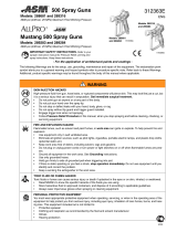
Operating Instructions
150 RPX Pressure Roller
and Spray System
Table of Contents
Warnings 2. . . . . . . . . . . . . . . . . . . . . . . . .
Pressure Relief 6. . . . . . . . . . . . . . . . . . .
Component Identification 7. . . . . . . . .
Setup 8. . . . . . . . . . . . . . . . . . . . . . . . . . . . .
Priming 9. . . . . . . . . . . . . . . . . . . . . . . . . .
Operation 13. . . . . . . . . . . . . . . . . . . . . . . .
Cleanup 17. . . . . . . . . . . . . . . . . . . . . . . . .
Trouble Shooting 28. . . . . . . . . . . . . . . .
Service 31. . . . . . . . . . . . . . . . . . . . . . . . . .
Parts 36. . . . . . . . . . . . . . . . . . . . . . . . . . . .
Technical Information 42. . . . . . . . . . .
Graco Warranty 44. . . . . . . . . . . . . . . . . .
Graco Phone Number 44. . . . . . . . . . .
309388
Rev. J
2800 psi (193 bar, 19 MPa) Maximum Working Pressure*
Model 233687, Series B
* The best operating pressure is the lowest pressure that provides an even paint supply to the roller and
typically does not exceed 300 psi (2.1 MPa, 21 bar).
Also Includes: ContractortIn–line Valve 244161
and Pressure Roller 244279
D 20 in. (50 cm) heavy-duty extension
D 3/16 in. x 25 ft DuraFlext hose
D 9 in. (23 cm) roller frame
D 1/2 in. (13 mm) nap roller cover
– For roller and portable spray application
of architectural paints and coatings –
Important Safety Instructions
Read all warnings and instructions in this
manual. Save these instructions.
Use water based or mineral spirit–type material
only. Do not use materials having flash points
lower than 70_ (21_). For information about
your material request MSDS from distributor or
retailer.
GRACO INC.ąP.O. BOX 1441ąMINNEAPOLIS, MNą55440-1441
ECOPYRIGHT 2001, GRACO INC.
Graco Inc. is registered to I.S. EN ISO 9001

2 309388
Specifications
This equipment is not intended for use with flammable or combustible materials used in places such as
cabinet shops or other “factory” or fixed locations. If you intend to use this equipment in this type of
application, you must comply with NFPA 33 and OSHA requirements for the use of flammable and
combustible materials.
The following are general warnings related to the setup, use, grounding, maintenance, and repair of this equipment.
Additional, more specific warnings may be found throughout the body of this manual where applicable. Symbols
appearing in the body of the manual refer to these general warnings. When these symbols appear throughout the
manual, refer back to these pages for a description of the specific hazard.
WARNING
FIRE AND EXPLOSION HAZARD
Flammable fumes, such as solvent and paint fumes, in work area can ignite or explode. To help
prevent fire and explosion:
D Use equipment only in well ventilated area.
D Eliminate all ignition sources; such as pilot lights, cigarettes, portable electric lamps, and plastic
drop clothes (potential static arc).
D Sprayer generates sparks. When flammable liquid is used in or near sprayer or for flushing or
cleaning, keep sprayer at least 20 ft (6 m) away from explosive vapors.
D Keep work area free of debris, including solvent, rags and gasoline.
D Do not plug or unplug power cords or turn lights on or off when flammable fumes are present.
D Ground equipment and conductive objects in work area. Read Grounding instructions.
D If there is static sparking or you feel a shock, stop operating immediately. Do not use equipment
until you identify and correct the problem.
D Keep a fire extinguisher in the work area.
ELECTRIC SHOCK HAZARD
Improper grounding, setup, or usage of the system can cause electric shock.
D Turn off and disconnect power cord before servicing equipment.
D Use only grounded electrical outlets
D Use only 3–wire extension cords.
D Ensure ground prongs are intact on sprayer and extension cords.
D Do not expose to rain. Store indoors.

3309388
SKIN INJECTION HAZARD
High pressure fluid from gun, hose leaks, or ruptured components will pierce skin. This may look like
just a cut, but it is a serious injury that can result in amputation. Get immediate surgical attention.
D Do not point gun at anyone or any part of the body.
D Do not put your hand over the spray tip.
D Do not stop or deflect leaks with your hand, body, glove, or rag.
D Engage trigger lock when not spraying.
D Follow Pressure Relief Procedure in this manual, when you stop spraying and before cleaning,
checking or servicing equipment.
INSTRUCTIONS
EQUIPMENT MISUSE HAZARD
Misuse can cause death or serious injury.
D Do not exceed the maximum working pressure or temperature rating of the lowest rated system
component. Read Technical Data in all equipment manuals.
D Use fluids and solvents that are compatible with equipment wetted parts. Read Technical Data in
all equipment manuals. Read fluid and solvent manufacturer’s warnings. For complete information
about your material, request MSDS from distributor or retailer.
D Check equipment daily. Repair or replace worn or damaged parts immediately with genuine Graco
replacement parts only.
D Do not alter or modify equipment.
D Use equipment only for its intended purpose. Call your Graco distributor for information.
D Route hoses and cables away from traffic areas, sharp edges, moving parts and hot surfaces.
D Do not kink or overbend hoses or use hoses to pull equipment.
D Keep children and animals away from work area.
D Do not operate the unit when fatigured or under the influence of drugs or alcohol.
D Comply with all applicable safety regulations.
PRESSURIZED ALUMINUM PARTS HAZARD
Do not use 1,1,1-trichloroethane, methylene chloride, other halogenated hydrocarbon solvents or
fluids containing such solvents in this equipment. Such use could result in a serious chemical reaction,
with the possibility of explosion, which could cause death, serious injury and/or substantial property
damage.
TOXIC FLUID HAZARD
Toxic fluid or fumes can cause serious injury or death if splashed in the eyes or on skin, inhaled, or
swallowed.
D Read MSDS’s to know the specific hazards of the fluids you are using.
D Store hazardous fluid in approved containers and dispose of it according to all applicable guide-
lines.
PERSONAL PROTECTIVE EQUIPMENT
You must wear appropriate protective equipment when operating, servicing, or when in the operating
area of the equipment to help protect you from serious injury, including eye injury, inhalation of toxic
fumes, burns, and hearing loss. This equipment includes, but is not limited to:
D Protective eye wear.
D Clothing and respirator as recommended by the fluid and solvent manufacturer.
D Gloves.
D Hearing protection.

4 309388
D The sprayer requires a 120V AC, 60 Hz, 15A circuit
with grounding receptacle. Never use an outlet that is
not grounded or an adapter.
D Do not use the sprayer if the electrical cord has a damaged
ground prong. Only use an extension cord with an undamaged,
3–prong plug.
D Recommended extension cords for use with this sprayer:
D 25 ft (7.6 m) 18 AWG
D 50 ft (15.2 m) 16 AWG
D 100 ft (30.5 m) 14 AWG
D 150 ft. (45.7 m) 12 AWG
Smaller gauge or longer extension cords may reduce sprayer
performance.
Grounding and Electric Requirements
ti5572a
D Ground sprayer gun through connection to a
properly grounded fluid hose and pump.
D Ground fluid supply container. Follow local code.
The sprayer must be grounded. Grounding reduces the risk of static
and electric shock by providing and escape wire for the electrical
current due to static build up or in the event of a short circuit.
ti3001b

5309388
Grounding and Electric Requirements
D Ground solvent pails used when flushing. Follow local code. Use
only conductive, metal pails, placed on a grounded surface such as
concrete. Do not place the pail on a non–conductive surface such
as paper or cardboard, which interrupts the grounding continuity.
ti5850a
ti5851a
D Ground the metal pail by connecting a ground wire to the
pail by clamping one end to pail and the other end to
ground such as as water pipe.
D Maintain grounding continuity when flushing or
relieving pressure by holding metal part of spray gun
firmly to side of a grounded metal pail, then trigger gun.
Thermal Overload
D Motor has a thermal overload switch
to shut itself down if overheated.
To reduce risk of injury from motor staring
unexpectedly when it cools, always turn power
switch OFF if motor shuts down.

6 309388
1. Turn power switch OFF and unplug power
cord.
2. Turn Spray–Prime/Drain valve to
PRIME/DRAIN to relieve pressure.
Pressure Relief Procedure
3. Turn pressure to lowest setting. Hold metal
part of gun firmly to a grounded metal pail.
Trigger gun to relieve pressure.
4. Engage trigger lock.
D Leave Spray–Prime/Drain valve in PRIME/
DRAIN position until you are ready to spray
again.
D If you suspect the spray tip is clogged or
that pressure has not been fully relieved
after following the above steps, VERY
SLOWLY loosen tip guard retaining nut or
hose end coupling to relieve pressure
gradually. Then loosen completely. Clear
hose or tip obstruction.
PRIME
PRIME

7309388
Contractort In–line Valve
Power Switch
Pressure Control Knob
Component Identification
Suction Tube
Inlet Screen
Spray/Prime Valve
Prime/drain position
Paint position
Prime Tube
Pressure Roller
Fluid Outlet Fitting

8 309388
1. Turn power switch OFF.
2. Connect one end of grounded fluid hose
to the In–line Valve. Use a wrench to
tighten.
Setup
3. Connect other end of hose to sprayer
fluid outlet fitting. Use a wrench to
tighten.
4. Turn pressure control knob all the way left
(counterclockwise) to minimum pressure.
NOTE: The Contractort In–line Valve
can be used as an airless spray gun
for small jobs by attaching a Handtite-
t Guard and RAC5 Switchtip.
For larger jobs the sprayer can be
used for airless spraying by attaching
an airless spray gun rated at 2800 psi
(193 bar, 19 MPa) Maximum Working
Pressure or higher.

9309388
1. Turn Spray/Prime valve to PRIME.
2. Separate the (smaller) prime tube from
the (larger) suction tube.
Priming – For flushing factory or storage fluid and loading pump with water
3. Unscrew inlet screen from suction tube.
4. Place prime tube in waste pail.
prime
tube
suction
tube
WASTE
prime tube

10 309388
5. Screw Power Flush attachment (included with
sprayer) onto garden hose and OPEN Power
Flush attachment.
6. Screw garden hose and Power Flush
attachment onto suction tube and turn
ON garden hose.
Priming – For flushing factory or storage fluid and loading pump with water
7. Plug sprayer in to grounded outlet and turn
power switch ON.
8. Align arrow on sprayer pressure
control knob to (bucket symbol) until
the pump starts.
garden hose
open closed
Power Flush attachment
Power Flush
attachment
suction tube
garden hose
(turn on)
30 to 60
seconds
WASTE
9. Let water flow out of prime tube into waste
pail for 30 to 60 seconds. Water flowing
out of prime tube indicates pump is primed
with water.

11309388
1. Turn power switch OFF.
Priming – For flushing water and loading pump and hose with paint
2. Turn Power Flush to closed position and
garden hose OFF. Unscrew Power Flush
attachment from suction hose.
3. Screw inlet screen onto suction tube.
PAINT
4. Submerge suction tube in paint.

12 309388
5. Point In–line Valve into waste pail.
Priming – For flushing water and loading pump and hose with paint
6. Turn power switch ON.
7. When paint starts to come out of prime tube,
pull and hold In–line Valve trigger and turn
Spray/Prime valve to spray. When paint
comes out of In–line Valve release trigger.
NOTE: The motor stopping indicates the
pump and hose are primed with paint.
8. Transfer prime tube to paint pail.
paint
PAINT
WASTE
WASTE
Release trigger
SPRAY

13309388
1. Engage the In–line Valve safety latch.
Operation
NOTE: Trigger the In–line Valve briefly
only when you need more paint. Determine
how often you must trigger the gun to
maintain an even paint supply to the roller.
2. Firmly tighten pressure roller to 20” extension.
3. Attach pressure roller assembly to In–line
Valve. Use a wrench to tighten.
4. Turn pressure control knob to roller symbol.
5. Disengage In–line Valve safety latch.
Trigger In–line Valve and roll the surface
until paint comes to roller.

14 309388
Operation
6. Increase pump pressure only if triggering
In–line Valve cannot supply enough paint
for your rolling speed.
7. Whenever you stop painting, relieve
pressure, page 6, and elevate roller
end of extension tube to prevent
paint from draining out.
Flush the pump, In–line Valve and
pressure roller immediately after
each use to prevent paint from drying
in the pressure roller and damaging
it. Cleanup page 17.

15309388
Rolling Techniques
1. Rolling vertically, roll out the letter “M”.
2. Cross roll, horizontally, to spread the
paint.
3. Finish with light vertical strokes until the
entire area has been evenly covered.

16 309388
Ceilings, Woodwork and Walls
1. Ceilings: Using a paint brush, apply a
starting row of paint approximately the
width of your brush where the walls and
ceiling meet.
2. With the roller, apply paint to the ceiling,
working the short way of the room and
applying as wide a strip as possible.
1. Woodwork & Walls: Using a brush,
paint woodwork first. Apply a starting
row of paint approximately the width of
the paint brush around the woodwork and
where the walls meet the ceiling.
2. With the roller, apply paint to the walls,
following the Roller Techniques described on
page 15.

17309388
Cleanup
1. Relieve the pressure. Turn power switch
OFF.
2. Remove roller cover and diffuser from roller frame
as follows:
a. Using your thumb, slide clip down and release
end caps, diffuser, and roller cover into a pail.
b. Remove roller cover from diffuser.
Leave the roller assembly attached to the In–line Valve for this procedure.
c. Pull end caps off diffuser.

18 309388
3. Clean roller cover, caps and diffuser with water or a
compatible solvent for non–water–based materials.
4. Place roller frame in paint pail. Be sure the holes in the
frame are facing inside the paint pail.
5. Place suction tube in bucket of water or compatible
solvent for non–water–based materials.
6. Turn pressure control knob to roller symbol.
Cleanup (continued)
Solvent
Paint
Solvent

19309388
7. Turn power switch ON.
Cleanup (continued)
8. Trigger In–line Valve.
9. Turn Spray/Prime valve to SPRAY.
10. Continue to trigger In–line Valve until flushing
fluid begins to dilute paint. Then release
In–line Valve trigger.
11. Place roller frame in another bucket.
If you are flushing a non–water–based fluid, flush
until fluid coming out of roller frame is clear. Proceed
to page 25, Cleanup–Cleaning Contractort In–line
Valve Filter.
If water–based, follow Power Flushing procedure,
page 20.
12. Relieve pressure, page 6. Turn power
switch OFF.
Solvent

20 309388
1. Relieve pressure, page 6. Turn power switch OFF.
2. Screw Power Flush attachment onto garden hose.
3. Turn lever to close Power Flush attachment.
garden hose
open
closed
Power Flush attachment
close
WASTE
inlet screen
Cleanup – Power Flushing After Spraying Water–based Paint
4. Unscrew inlet screen from suction tube and place in
waste pail.
/