Page is loading ...

PARTS LIST
INCLUDED
Frymaster, a member of the Commercial Food Equipment Service Association, recommends
using CFESA Certified Technicians.
Price: $10.00
*8195941*
24-Hour Service Hotline
1-800-551-8633 819-5941
OCTOBER 2002
TB14 Series Gas Fryers
Installation & Operation Manual
TB14 Series With Built-In Filtration

Please read all sections of this manual and retain for future reference.
NOTICE
This appliance is intended for professional use only and is to be operated by qualified
personnel only. A Frymaster/Dean Factory Authorized Service Center (FASC) or other qualified
professional should perform installation, maintenance, and repairs. Installation, maintenance,
or repairs by unqualified personnel may void the manufacturer’s warranty. See Chapter 1 of
this manual for definitions of qualified personnel.
NOTICE
This equipment must be installed in accordance with the appropriate national and local codes of
the country and/or region in which the appliance is installed. See NATIONAL CODE
REQUIREMENTS in Chapter 3 of this manual for specifics.
NOTICE
Drawings and photos used in this manual are intended to illustrate operational, cleaning and
technical procedures and may not conform to onsite management operational procedures.
NOTICE TO OWNERS OF UNITS EQUIPPED WITH COMPUTERS
U.S.
This device complies with Part 15 of the FCC rules. Operation is subject to the following two
conditions: 1) This device may not cause harmful interference, and 2) This device must accept
any interference received, including interference that may cause undesired operation. While
this device is a verified Class A device, it has been shown to meet Class B limits.
CANADA
This digital apparatus does not exceed the Class A or B limits for radio noise emissions as set
out by the ICES-003 standard of the Canadian Department of Communications.
Cet appareil numerique n’emet pas de bruits radioelectriques depassany les limites de classe A
et B prescrites dans la norme NMB-003 edictee par le Ministre des Communications du Canada.
DANGER
Improper installation, adjustment, maintenance or service, and unauthorized alterations or
modifications can cause property damage, injury, or death. Read the installation, operating and
service instructions thoroughly before installing or servicing this equipment. Only qualified
service personnel may convert this appliance to use a gas other than that for which it was
originally configured. See Chapter 1 of this manual for definition of qualified service personnel.
NOTICE
The Commonwealth of Massachusetts requires any and all gas products to be installed by a
licensed plumber or pipe fitter.

DANGER
Adequate means must be provided to limit the movement of this appliance without depending
upon the gas line connection. Single fryers equipped with legs must be stabilized by installing
anchor straps. All fryers equipped with casters must be stabilized by installing restraining
chains. If a flexible gas line is used, an additional restraining cable must be connected at all
times when the fryer is in use.
DANGER
The front ledge of the fryer is not a step. Do not stand on the fryer. Serious injury can result
from slips or contact with the hot oil.
DANGER
Do not store or use gasoline or other flammable vapors and liquids in the vicinity of this or any
other appliance.
DANGER
Instructions to be followed in the event the operator smells gas or otherwise detects a gas leak
must be posted in a prominent location. This information can be obtained from the local gas
company or gas supplier.
NOTICE
If, during the warranty period, the customer uses a part for this Enodis equipment other than an
unmodified new or recycled part purchased directly from Frymaster/Dean, or any of its
authorized service centers, and/or the part being used is modified from its original
configuration, this warranty will be void. Further, Frymaster/Dean and its affiliates will not be
liable for any claims, damages or expenses incurred by the customer which arise directly or
indirectly, in whole or in part, due to the installation of any modified part and/or part received
from an unauthorized service center.
DANGER
The crumb tray in fryers equipped with a filter system must be emptied into a fireproof container
at the end of frying operations each day. Some food particles can spontaneously combust if left
soaking in certain shortening material. Additional information can be obtained in the filtration
manual included with the system.
WARNING
No structural material on the fryer should be altered or removed to accommodate placement of
the fryer under a hood. Questions? Call the Frymaster/Dean Service Hotline at 1-800-551-8633.
WARNING
Do not bang fry baskets or other utensils on the fryer’s joiner strip. The strip is present to seal
the joint between the frypot. Banging fry baskets on the strip to dislodge shortening will distort
the strip, adversely affecting its fit. It is designed for a tight fit and should only be removed for
cleaning.

TB14 Series Gas Fryers
Installation & Operation Manual
TABLE OF CONTENTS
Page #
1. INTRODUCTION 1-1
1.1 After Purchase 1-1
1.2 Ordering Parts 1-1
1.3 Service Information 1-1
1.4 Computer Information 1-1
1.5 Safety Information 1-2
1.6 Service Personnel 1-2
2. IMPORTANT INFORMATION 2-1
2.1 Product Description 2-1
2.2 Principles of Operation 2-1
2.3 Rating Plate 2-1
2.4 Pre-Installation 2-1
2.5 Air Supply and Ventilation 2-3
2.6 Equipment Installed at High Altitudes 2-3
2.7 Receiving and Unpacking Equipment 2-4
3. INSTALLATION 3-1
3.1 Installing the Fryer 3-1
3.2 Leveling the Fryer (fryers equipped with legs only) 3-1
3.3 Installing Casters and Legs 3-2
3.4 Gas Categories 3-3
3.5 Electrical Connections 3-6
4. FRYER OPERATIONS 4-1
4.1 Initial Start-up 4-1
4.2 Boil-Out Procedure 4-3
4.3 Final Preparation 4-4

TB14 Series Gas Fryers
Installation & Operation Manual
TABLE OF CONTENTS (CONT.)
Page #
5. BUILT-IN FILTRATION 5-1
5.1 General 5-2
5.2 Filtration Preparation 5-3
5.3 Daily Filtration Operation 5-6
5.4 Operating the Filter 5-7
6. COMPUTER OPERATION 6-1
6.1 Operating Fryers with Computer Magic III.5 Computers 6-1
6.2 Programming the Computer Magic III.5 Computer 6-4
7. PREVENTATIVE MAINTENANCE 7-1
7.1 General 7-1
7.2 Daily 7-1
7.3 Weekly 7-1
7.4 Periodic/Annual 7-2
7.5 Stainless Steel 7-3
8. TROUBLESHOOTING 8-1
8.1 General 8-1
8.2 Pilot Burner Malfunction 8-1
8.3 Main Burner Malfunctions 8-2
8.4 Wiring Diagrams 8-4
9. PARTS LIST 9-1
9.1 Accessories 9-1
9.2 Cabinetry and Related Components 9-2
9.3 Computer and Related Components 9-4
9.4 Filter Module Components 9-5
9.5 Filter Pan Components 9-7
9.6 Frypot, Burners and Related Components 9-8
9.7 Oil Return Components 9-10

TB14 SERIES GAS FRYERS
CHAPTER 1: INTRODUCTION
1-1
1.1 After Purchase
In order to improve service, have the following chart filled in by the Frymaster Authorized Service
Technician who installed this equipment.
Authorized Service
Technician/FASC
Address
Telephone/Fax
Model Number
Serial Number
Gas Type
1.2 Ordering Parts
Customers may order parts directly from their local factory authorized service center. For this
address and phone number, contact your factory authorized service center or call the Frymaster
Service Hotline phone number, 1-800-551-8633.
To speed up your order, provide the model number, serial number, gas type, part needed, item part
number (if known), and quantity needed.
1.3 Service Information
Call the Frymaster Service Hotline, 1-800-551-8633, for the location of your nearest factory
authorized service center. To assist you more efficiently, always provide the service technician with
the model number, gas type, serial number, and the nature of the problem.
1.4 Computer Information
This equipment has been tested and found to comply with the limits for a Class A digital device,
pursuant to Part 15 of the FCC rules. While this device is a verified Class A device, it has been
shown to meet the Class B limits. These limits are designed to provide reasonable protection against
harmful interference when the equipment is operated in a commercial environment. This equipment
generates, uses and can radiate radio frequency energy and, if not installed and used in accordance
with the instruction manual, may cause harmful interference to radio communications. Operation of
the equipment in a residential area is likely to cause harmful interference in which case the user will
be required to correct the interference at his own expense.

TB14 SERIES GAS FRYERS
CHAPTER 1: INTRODUCTION
1-2
1.4 Computer Information (cont.)
The user is cautioned that any changes or modifications not expressly approved by the party
responsible for compliance could void the user's authority to operate the equipment.
If necessary, the user should consult the dealer or an experienced radio and television technician for
additional suggestions.
The user may find the following booklet prepared by the Federal Communications Commission
helpful: "How to Identify and Resolve Radio-TV Interference Problems". This booklet is available
from the U.S. Government Printing Office, Washington, DC 20402, Stock No. 004-000-00345-4.
1.5 Safety Information
Before attempting to operate your unit, read the instructions in this manual thoroughly.
Throughout this manual, you will find notations enclosed in double-bordered boxes similar to the
ones below.
CAUTION
CAUTION boxes contain information about actions or conditions that may cause or result in a
malfunction of your system.
WARNING
WARNING boxes contain information about actions or conditions that may cause or result in
damage to your system, and which may cause your system to malfunction.
DANGER
DANGER boxes contain information about actions or conditions that may cause or result in injury
to personnel, and which may cause damage to your system and/or cause your system to malfunction.
1.6 Service Personnel
1.6.1 Definitions
A. Qualified and/or Authorized Operating Personnel
1. Qualified/authorized operating personnel are those who have carefully read the information
in this manual and have familiarized themselves with the equipment functions, or have had
previous experience with the operation of equipment covered in this manual.

TB14 SERIES GAS FRYERS
CHAPTER 1: INTRODUCTION
1-3
1.6.1 Definitions (cont.)
B. Qualified Installation Personnel
1. Qualified/authorized personnel are those who have carefully read the information in this
manual and have familiarized themselves with the equipment functions, or who have had
previous experience with the operation of the equipment covered in this manual.
C. Qualified Service Personnel
1. Qualified service personnel are those who are familiar with Frymaster equipment and have
been authorized by Frymaster to perform service on Frymaster equipment. All authorized
service personnel are required to be equipped with a complete set of service parts manuals
and stock a minimum amount of parts for Frymaster equipment. A list of Frymaster Factory
Authorized Service Centers (FASCs) was included with the fryer when shipped from the
factory. Failure to use qualified service personnel will void the Frymaster warranty on
your equipment.

TB14 SERIES GAS FRYERS
CHAPTER 2: IMPORTANT INFORMATION
2-1
2.1 Product Description
Frymaster TB14 Series gas fryers are energy-efficient, tube-style, gas-fired units, design-certified by
the International Approval Services (AGA/CGA), National Sanitation Foundation (NSF), and
manufactured to their basic performance and application specifications.
All units are shipped completely assembled with accessories packed inside the frypot. All units are
adjusted, tested and inspected at the factory before shipment. Sizes, weights and input rates of all
models are listed in this manual.
NOTE: The on-site supervisor is responsible for ensuring that operators are made aware of inherent
dangers of operating a deep fat fryer, particularly aspects of oil filtration, draining, and
cleaning of the fryer.
2.2 Principles of Operation
The incoming gas flows through orifices and is mixed with air in the burners to create the correct
ratio for proper combustion. The mixture is ignited at the front end of each heat tube by the pilot
light. Internal diffusers slow the flame as it goes through the burner tube. This slower and more
turbulent flame gives much better heat transfer to the walls of the tubes, thereby heating the oil
better.
2.3 Rating Plate
The rating plate is attached to the inside right-hand corner of the front door panel. Information
provided includes the model and serial number of the fryer, BTU/hr input of the burners, outlet gas
pressure in inches W.C. (mbars) and whether the unit has natural or propane gas orifices.
DANGER
Fryers MUST be connected ONLY to the gas type identified on the attached rating
plate.
2.4 Pre-Installation
A. General: Only a licensed gas fitter should install any gas-fired equipment.
1. A manual gas shut-off valve must be installed in the gas supply line ahead of the fryers for
safety and ease of future service.

TB14 SERIES GAS FRYERS
CHAPTER 2: IMPORTANT INFORMATION
2-2
2.4 Pre-Installation (cont.)
2. Frymaster TB14 Series gas fryers require 120VAC 60 cycle or 230VAC single-phase 50-
hertz (International/CE) electrical service and are equipped with a 16-3 SJT grounded
flexible power cord for a direct connection to the power supply. Amperage draw for each
unit depends on the accessories supplied with the unit/system.
B. Clearances: The fryer area must be kept free and clear of all combustibles. This unit is design-
certified for the following installations:
1. Commercial installation only (not for household use).
2. Non-combustible floor installation equipped with factory-supplied 6-inch (15-cm) adjustable
legs or 5-inch (13-cm) casters;
3. Combustible construction with a minimum clearance of 6-inches (15-cm) side and 6-inches
(15-cm) rear, and equipped with factory-supplied 6-inch (15-cm) adjustable legs or 5-inch
(13-cm) casters.
DANGER
Local building codes usually prohibit a fryer with its open tank of hot oil from being
installed beside an open flame of any type, whether a broiler or the open burner of a
range.
C. Installation Standards:
1. U.S. installations must meet: 2. Canadian installations must meet:
American National Standard Institute CAN 1-B149 Installation Codes
ANSI Z83.11 Canadian Gas Association
American Gas Association 55 Scarsdale Road
8501 E. Pleasant Valley Road Don Mills, ONT, M3B 2R3
Cleveland, OH 44131
National Electrical Code Canadian Electric Code c22.1, part 1
ANSI/NFPA #70 Canadian Standards Association
American National Standard Institute 178 Rexdale Blvd.
1430 Broadway Rexdale, ONT, M9W 1R3
New York, NY 10018
NFPA Standards #96 and #211
National Fire Protection Association
470 Atlantic Avenue
Boston, MA 02110

TB14 SERIES GAS FRYERS
CHAPTER 2: IMPORTANT INFORMATION
2-3
2.4 Pre-Installation (cont.)
3. CE/EXPORT STANDARDS: Fryer installation must conform with local codes, or in the absence
of local codes, to the appropriate national or European Community (CE) standards.
2.5 Air Supply and Ventilation
Keep the area around the fryer clear to prevent obstruction of combustion and ventilation airflow as
well as for service and maintenance.
A. Do not connect this fryer to an exhaust duct.
B. Correct installation and adjustment will ensure adequate airflow to the fryer system.
C. A commercial, heavy-duty fryer must vent its combustion wastes to the outside of the
building. A deep-fat fryer must be installed under a powered exhaust hood, or an exhaust fan
must be provided in the wall above the unit, as exhaust gas temperatures are approximately
800-1000°F (427-538°C). Check air movement during installation. Strong exhaust fans in
the exhaust hood or in the overall air conditioning system can produce slight air drafts in the
room.
D. Do not place the fryer’s flue outlet directly into the plenum of the hood, as it will affect the
gas combustion of the fryer.
E. Never use the interior of the fryer cabinet for storage or store items on shelving over or
behind the fryer. Exhaust temperatures can exceed 800°F (427ºC) and may damage or melt
items stored in or near the fryer.
F. Adequate distance must be maintained from the flue outlet of the fryer(s) to the lower edge
of the filter bank. Per NFPA Standards No. 96, a minimum of 18-inches (45-cm) should be
maintained between the flue(s) and the lower edge of the exhaust hood filter.
G. Filters and drip troughs should be part of any industrial hood, but consult local codes before
constructing and installing any hood. The duct system, the exhaust hood and the filter bank
must be cleaned on a regular basis and kept free of grease.
2.6 Equipment Installed at High Altitudes
A. The fryer input rating (BTU/hr) is for elevations up to 2,000 feet (610-m). For elevations
above 2,000 feet (610-m), the rating should be reduced four percent for each additional 1,000
feet (305-m) above sea level.
B. The correct orifices are installed at the factory if operating altitude is known at time of the
customer’s order.

TB14 SERIES GAS FRYERS
CHAPTER 2: IMPORTANT INFORMATION
2-4
2.7 Receiving and Unpacking Equipment
A. Check that the container is upright. Use an outward prying motion - no hammering - to
remove the carton. Unpack the fryer carefully and remove all accessories from the carton.
Do not discard or misplace these, as they will be needed.
B. After unpacking, immediately check the equipment for visible signs of shipping damage. If
damage has occurred, contact the carrier and file the appropriate freight claims. Do not
contact the factory. Shipping damage responsibility is between the carrier and the dealer.
If your equipment arrives damaged:
1. File claim for damages immediately, regardless of extent of damage.
2. Visible loss or damage: Be sure this is noted on the freight bill or express receipt and is
signed by the person making the delivery.
3. Concealed loss or damage: If damage is unnoticed until equipment is unpacked, notify
freight company or carrier immediately, and file a concealed damage claim. This should
be done within 15 days of date of delivery. Be sure to retain container and all packing
materials for inspection.
NOTE: Frymaster Does Not Assume Responsibility for Damage or Loss Incurred in
Transit.
C. Remove all plastic skin from sides, front, and doors of the fryer(s). Failure to do this prior to
initial fryer operation will make it very difficult to remove later.

TB14 SERIES GAS FRYERS
CHAPTER 3: INSTALLATION
3-1
3.1 Installing the Fryer
A. Initial Installation: If the fryer is installed with legs, do not push the fryer to adjust its
position. Use a pallet or lift jack to lift the fryer slightly, then place the fryer where it is to be
installed.
B. Relocating the fryer: Remove all weight from each leg before moving a fryer with legs
installed. Do not slide the fryer on the legs.
C. If a leg becomes damaged, contact your service agent for immediate repair/replacement.
3.2 Leveling the Fryer (fryers equipped with legs only)
A. All Installations: If the floor is uneven or has a definite slope, it is recommended to place
the fryer on an even platform.
B. Place a spirit level across the top of the fryer and level the unit both front-to-back and side-
to-side. If it is not level, the unit may not function efficiently, the oil may not drain properly
for filtering and in a line-up it may not match adjacent units.
C. Adjust to the high corner and measure with the spirit level. If floor is uneven, level the unit
with the screw adjustments on each leg (ensure minimum clearances as discussed in
Chapter 2 are maintained during the leveling procedure).
D. Re-leveling: If the fryer is moved, re-level the fryer following the above instructions.
E. The install must be reviewed at the time of installation to ensure it meets the intent of these
instructions.
CAUTION
Fryers must be at room temperature, empty of oil, and if fitted with legs, lifted during
movement to avoid damage and possible bodily injury.
DANGER
Hot shortening can cause severe burns. Avoid contact. Under all circumstances, oil
must be removed from the fryer before attempting to move it to avoid oil spills, and
the falls and severe burns that could occur. This fryer may tip and cause personal
injury if not secured in a stationary position.

TB14 SERIES GAS FRYERS
CHAPTER 3: INSTALLATION
3-2
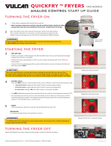
3.3 Installing Casters and Legs
A. Install casters and/or legs near where the fryer is to be used, as neither is secure for long
transit. TB14 Series gas fryers cannot be curb mounted and must be equipped with either
legs or casters provided.
B. After unpacking, use a pallet or lift jack to raise the unit before installing the casters.
C. Align the caster or leg base holes with the leg support assembly and insert bolt. Install the
washers and nut hand tight, and repeat for all four holes in caster/leg base assembly.
D. Tighten the caster/leg against the leg support assembly by using appropriate tools. Ensure
that all four bolts are evenly tightened.
E. For fryers with casters, there are no built-in leveling devices. The floor where the fryers
are installed must be level.
1/4-20 x 3/4 Hex Bolt
1/4-20 Hex Head Locknut
Washer
Leg Support Assembly
Front Channel or
Rear Channel
1/4-20 x 3/4 Hex Bolt
Front Channel
or Rear Channel
Front or Rear Leg with
Mounting Plate
Adjust as needed
Front View
Rear Side View
Rear Caster—5" Rigid
Optional Caster-
Rear Only
Front Caster—5" Swivel
w/Brake
Optional Caster-
Front Only
WARNING
Frymaster fryers equipped with legs are for permanent installations. Fryers fitted
with legs must be lifted during movement to avoid damage and possible bodily
injury. For a moveable or portable installation, Frymaster optional equipment casters
must be used.
Questions? Call 1-800-551-8633
Caster/Leg Installation and Adjustment

TB14 SERIES GAS FRYERS
CHAPTER 3: INSTALLATION
3-3
3.4 Gas Connections
DANGER
Before connecting new pipe to this appliance the pipe must be blown out thoroughly
to remove all foreign material. Foreign material in the burner and gas controls will
cause improper and dangerous operation.
NATIONAL CODE REQUIREMENTS
This equipment is to be installed in compliance with the Basic Plumbing Code of the Building
Officials and Code Administrators International, Inc. (BOCA) and the Food Service Sanitation
Manual of the U.S. Food and Drug Administration.
This equipment is manufactured to use the type of gas specified on the rating plate attached to the
door. Connect equipment stamped "NAT" only to natural gas and that stamped "PRO" only to LP
(Propane) gas.
Installation shall be made with a gas connector that complies with national and local codes.
Quick disconnect devices, if used, shall likewise comply with national and local codes.
DANGER
The fryer MUST be connected to the gas supply specified on the rating and serial number
plate located on the back of the fryer door.
DANGER
If gas odors are detected, the gas supply MUST be shut off at the main shut-off valve. The
local gas company or FASC should be contacted immediately to rectify the problem.
A. The gas supply (service) line must be the same size or greater than the fryer inlet line. This
fryer is equipped with a 3/4" (22 mm) male inlet. The gas supply line must be sized to
accommodate all the gas-fired equipment that may be connected to that gas supply. Consult
your contractor, gas company, supplier, or other knowledgeable authorities.
Recommended Gas Supply Line Sizes
Gas Types Number of Fryers
1 2 to 3 4 or more (*)
Natural Gas 3/4" (22 mm) 1" (28 mm) 1-1/4" (35 mm)
Propane Gas 1/2" (15 mm) 3/4" (22 mm) 1" (28 mm)
(*) When exceeding 18 feet (6 meters) for a configuration of more than four fryers, it is necessary
to provide a 1 1/4" (33 mm) rigid gas connection.

TB14 SERIES GAS FRYERS
CHAPTER 3: INSTALLATION
3-4
3.4 Gas Connections (cont.)
DANGER
All connections must be sealed with a joint compound suitable for the gas being
used and all connections must be tested with a solution of soapy water before
lighting any pilots.
Never use matches, candles, or any other ignition source to check for leaks. If gas
odors are detected, shut off the gas supply to the appliance at the main shut-off
valve and immediately contact the local gas company or an authorized service
agency for service.
DANGER
"Dry-firing" your unit will cause damage to the frypot and can cause a fire. Always
ensure that melted shortening, cooking oil or water is in the frypot before firing the
unit.
B. Rigid Connections: Check any installer-supplied intake pipe(s) visually and clean threading
chips, or any other foreign matter before installing into a service line. If the intake pipes are
not clear of all foreign matter, the orifices will clog when gas pressure is applied. Seal pipe
joints with a sealant resistive to LP gas. When using thread compound on gas piping, use
very small amounts and only on male threads. Use a pipe thread compound that is not
affected by the chemical action of LP gases. DO NOT apply thread compound to the first
two pipe threads—doing so will cause clogging of the burner orifices and control valve.
C. Manual shut-off valve: This gas service supplier-installed valve must be installed in the gas
service line ahead of the fryers in the gas stream and in a position where it can be reached
quickly in the event of an emergency.
D. Regulating Gas Pressure: The fryer and shut-off valve must be disconnected from the gas
supply during any pressure testing of the system.
1. External gas regulators are not normally required on this fryer. A safety control valve
protects the fryer against pressure fluctuations. If the incoming pressure is in excess of
½" PSI (3.45 kPa/35 mbar), a step-down regulator will be required.
DANGER
When pressure-testing incoming gas supply lines, disconnect the fryer from the gas
line if the test pressure is ½" PSI [3.45 kPa (14 inches W.C.)] or greater to avoid
damage to the fryer’s gas piping and gas valve(s).

TB14 SERIES GAS FRYERS
CHAPTER 3: INSTALLATION
3-5
3.4 Gas Connections (cont.)
E. Manifold Pressure: Only qualified personnel should check the manifold pressure with a
manometer.
1. Check the rating plate for manifold gas pressures. Natural gas units normally require 4"
W.C., and propane units normally require 11" W.C. gas pressure.
2. Double check the arrow forged into the bottom of the regulator body, which indicates
gas flow direction. It should point downstream towards the fryers. The air vent cap is
also part of the regulator and should not be removed.
3. If a vent line from the gas pressure regulator is used, it should be installed in
accordance with local codes or in the absence of local codes, with the National Fuel
Gas Code, ANSI Z223.1-(latest edition).
WARNING
Use a diluted soap solution to find potentially dangerous gas leaks when making
new connections.
F. Regulators can be adjusted in the field, but it is recommended that they not be tampered with
unless the part is known to be out of adjustment or serious pressure fluctuations are found to
exist and can be solved no other way.
G. Only qualified service personnel should make adjustments to the regulators.
H. Orifices: The fryer can be configured to operate on any available gas. The correct safety
control valve, appropriate gas orifices, and pilot burner are installed at the factory. While the
valve can be adjusted in the field, only qualified service personnel should make any
adjustments with the proper test equipment.
I. Flexible Couplings, Connectors and Casters:
1. If the fryer is to be installed with flexible couplings and/or quick-disconnect fittings, the
installer must use a heavy-duty AGA design-certified commercial flexible connector of
at least 3/4" NPT (with suitable strain reliefs), in compliance with the Standard for
Connectors for Movable Gas Appliances, ANSI Z21.69-(latest edition) and Addenda
Z21.69a-(latest edition). Quick disconnect devices must comply with the Standard for
Quick-Disconnect Devices for Use with Gas Fuel, ANSI Z21.41-(latest edition).
WARNING
Do not attach accessories to this fryer unless fryer is secured from tipping. Personal
injury may result.
2. The fryer must be restrained by means independent of the flexible coupling or
connector in order to limit the movement of the fryer. Clips are located on the back
panel of the fryer for the attachment of restraints.

TB14 SERIES GAS FRYERS
CHAPTER 3: INSTALLATION
3-6
3.4 Gas Connections (cont.)
3. If disconnection of the restraint is necessary, this restraint must be reconnected after the
fryer has been returned to its originally installed position.
J. After hook-up, bleed the gas line of air to ensure that the pilot light will ignite quickly.
K. CE Standards: If the unit is to be installed with flexible coupling, use a commercial flexible
coupling certified as NF D 36123 (or other national standard) or a quick disconnect device
certified NF D 36124 (or other national standard).
3.5 Electrical Connections
The fryer when installed must be electrically grounded in accordance with local codes, or in the
absence of local codes, with the National Electrical Code, ANSI/NFPA 70-(latest edition).
DANGER
This fryer is equipped with a three-prong (grounding) plug for protection against
electrical shock and must be plugged directly into a properly grounded, three-prong
receptacle. DO NOT CUT, REMOVE, OR OTHERWISE BYPASS THE GROUNDING
PRONG ON THIS PLUG!
The rating plate and wiring diagram are located inside the front door. The fryer is equipped with a
120VAC single-phase 60-hertz system (Domestic), or 230VAC single-phase 50-hertz system
(International/CE). Do not cut or remove the ground prong from the power cord plug. Do not
attempt to use the fryer during a power outage.
DANGER
This appliance requires electrical power for operation. Place the gas control valve in
the OFF position in case of a prolonged power outage. Do not attempt to operate
this appliance during a power outage.

TB14 SERIES GAS FRYERS
CHAPTER 4: FRYER OPERATIONS
4-1
4.1 Initial Start-up
WARNING
The on-site supervisor is responsible for ensuring that operators are made aware of
the inherent hazards of operating a hot oil frying system, particularly the aspects of
system operation, oil filtration, draining and cleaning procedures.
A. Cleaning: New units are wiped clean with solvents at the factory to remove any visible signs
of dirt, oil, grease, etc. remaining from the manufacturing process, then coated lightly with
oil. Before any food preparation, wash thoroughly with hot, soapy water to remove any film
residue and dust or debris then rinse out and wipe dry. Also wash any accessories shipped
with the unit. Close the drain valve completely and remove the crumb screen covering the
heating tubes. Ensure the screws holding the thermostat and high-limit control sensing bulbs
into the frypot are tight.
WARNING
Do not bang fry baskets or other utensils on the fryer’s joiner strip. The strip is
present to seal the joint between the frypots. Banging fry baskets on the strip to
dislodge shortening will distort the strip, adversely affecting its fit. It is designed for
a tight fit and should only be removed for cleaning.
DANGER
Never operate this appliance with an empty frypot. The frypot must be filled with
water or cooking oil/shortening before lighting the burners. Failure to do so will
damage the frypot and may cause a fire.
WARNING
When checking for burner ignition or performance, do not get too close to the
burners. Slow ignition can cause possible flashback, increasing the potential for
facial and body burns.
4.1.1 Pilot Lighting Procedures, Standing Pilot Only
Initial Pilot Lighting: All Dean fryers are tested, adjusted and calibrated to sea level conditions
before leaving the factory. Adjustments to assure proper operation of pilot may be necessary on
installation to meet local conditions, low gas pressure, differences in altitude and variations in gas
characteristics. These adjustments correct possible problems caused by rough handling or vibration
during shipment, and are to be performed only by qualified service personnel. These adjustments
are the responsibility of the customer and/or the dealer and are not covered by the Dean Industries
warranty.

TB14 SERIES GAS FRYERS
CHAPTER 4: FRYER OPERATIONS
4-2
4.1.1 Pilot Lighting Procedures, Standing Pilot Only (cont.)
The inlet pipe at the lower rear of the fryer brings incoming gas to the pilot safety control valve, then
to the pilot and main burners. The pilot is located high in the cabinet center, at the base of the
frypot.
Light the pilot as follows:
1. Turn off the manual shut-off valve on the incoming service line.
2. Turn the operating thermostat or the computer off.
3. Depress the pilot gas cock dial on the combination control
valve and turn to "OFF".
4. Wait approximately 5 minutes for accumulated gas to
disperse.
Note: Inspect high-limit thermostat/temperature probe
location prior to filling frypot with water or oil. Ensure
that connecting hardware is intact and bulbs are properly
attached.
5. Fill the frypot with oil or water to the bottom OIL LEVEL line scribed on the frypot back.
Ensure that heating tubes are covered in liquid prior to engaging burners.
6. Open the manual shut-off valve on the incoming service line.
7. Apply lighted match or taper to the pilot burner head.
8. Turn the gas cock dial on the control valve to "Pilot", then
depress and hold the dial until the pilot stays lit
(approximately 1 minute).
9. If the pilot fails to stay lit, depress the dial and re-light the
pilot, depressing the dial longer before releasing.
10. When the pilot stays lit, turn the gas cock dial to "ON".
11. Turn computer on, then ensure the main burners ignite from
the pilot.
O
N
O
F
F
P
I
L
O
T
O
N
O
F
F
P
I
L
O
T
O
N
O
F
F
P
I
L
O
T
/