Page is loading ...

i
K9N Neo Series
MS-7260 (V1.X) Mainboard
G52-72601X1

ii
Copyright Notice
The material in this document is the intellectual property of MICRO-STAR
INTERNATIONAL. We take every care in the preparation of this document, but no
guarantee is given as to the correctness of its contents. Our products are under
continual improvement and we reserve the right to make changes without notice.
Trademarks
All trademarks are the properties of their respective owners.
NVIDIA, the NVIDIA logo, DualNet, and nForce are registered trademarks or trade-
marks of NVIDIA Corporation in the United States and/or other countries.
AMD, Athlon™, Athlon™ XP, Thoroughbred™, and Duron™ are registered trade-
marks of AMD Corporation.
Intel
®
and Pentium
®
are registered trademarks of Intel Corporation.
PS/2 and OS
®
/2 are registered trademarks of International Business Machines
Corporation.
Windows
®
95/98/2000/NT/XP are registered trademarks of Microsoft Corporation.
Netware
®
is a registered trademark of Novell, Inc.
Award
®
is a registered trademark of Phoenix Technologies Ltd.
AMI
®
is a registered trademark of American Megatrends Inc.
Revision History
Revision Revision History Date
V1.0 First release for PCB 1.0 April 2006
Technical Support
If a problem arises with your system and no solution can be obtained from the user’s
manual, please contact your place of purchase or local distributor. Alternatively,
please try the following help resources for further guidance.
Visit the MSI website for FAQ, technical guide, BIOS updates, driver updates,
and other information: http://www.msi.com.tw/program/service/faq/
faq/esc_faq_list.php
Contact our technical staff at: http://support.msi.com.tw/

iii
Safety Instructions
CAUTION: Danger of explosion if battery is incorrectly replaced.
Replace only with the same or equivalent type recommended by the
manufacturer.
1. Always read the safety instructions carefully.
2. Keep this User’s Manual for future reference.
3. Keep this equipment away from humidity.
4. Lay this equipment on a reliable flat surface before setting it up.
5. The openings on the enclosure are for air convection hence protects the equip-
ment from overheating. DO NOT COVER THE OPENINGS.
6. Make sure the voltage of the power source and adjust properly 110/220V be-
fore connecting the equipment to the power inlet.
7. Place the power cord such a way that people can not step on it. Do not place
anything over the power cord.
8. Always Unplug the Power Cord before inserting any add-on card or module.
9. All cautions and warnings on the equipment should be noted.
10. Never pour any liquid into the opening that could damage or cause electrical
shock.
11. If any of the following situations arises, get the equipment checked by a service
personnel:
† The power cord or plug is damaged.
† Liquid has penetrated into the equipment.
† The equipment has been exposed to moisture.
† The equipment has not work well or you can not get it work according to
User’s Manual.
† The equipment has dropped and damaged.
† The equipment has obvious sign of breakage.
12. DO NOT LEAVE THIS EQUIPMENT IN AN ENVIRONMENT UNCONDITIONED, STOR-
AGE TEMPERATURE ABOVE 60
0
C (140
0
F), IT MAY DAMAGE THE EQUIPMENT.

iv
FCC-B Radio Frequency Interference Statement
This equipment has been
tested and found to comply
with the limits for a Class B
digital device, pursuant to Part
15 of the FCC Rules. These limits are designed to provide reasonable protection
against harmful interference in a residential installation. This equipment generates,
uses and can radiate radio frequency energy and, if not installed and used in accor-
dance with the instructions, may cause harmful interference to radio communications.
However, there is no guarantee that interference will not occur in a particular
installation. If this equipment does cause harmful interference to radio or television
reception, which can be determined by turning the equipment off and on, the user is
encouraged to try to correct the interference by one or more of the measures listed
below.
† Reorient or relocate the receiving antenna.
† Increase the separation between the equipment and receiver.
† Connect the equipment into an outlet on a circuit different from that to
which the receiver is connected.
† Consult the dealer or an experienced radio/television technician for help.
Notice 1
The changes or modifications not expressly approved by the party responsible for
compliance could void the user’s authority to operate the equipment.
Notice 2
Shielded interface cables and A.C. power cord, if any, must be used in order to
comply with the emission limits.
VOIR LA NOTICE D ’INSTALLATION AVANT DE RACCORDER AU RESEAU.
Micro-Star International
MS-7260
This device complies with Part 15 of the FCC Rules. Operation is subject to the
following two conditions:
(1) this device may not cause harmful interference, and
(2) this device must accept any interference received, including interference that
may cause undesired operation.

v
WEEE (Waste Electrical and Electronic Equipment) Statement

vi

vii

viii
CONTENTS
Copyright Notice..............................................................................................................ii
Trademarks.......................................................................................................................ii
Revision History..............................................................................................................ii
Technical Support...........................................................................................................ii
Safety Instructions.........................................................................................................iii
FCC-B Radio Frequency Interference Statement........................................................iv
WEEE (Waste Electrical and Electronic Equipment) Statement....................................v
Chapter 1 Getting Started....................................................................................1-1
Mainboard Specifications...................................................................................1-2
Mainboard Layout................................................................................................1-4
Packing Checklist.................................................................................................1-5
Chapter 2 Hardware Setup..................................................................................2-1
Quick Components Guide....................................................................................2-2
CPU (Central Processing Unit)............................................................................2-3
CPU Installation Procedures for Socket AM2............................................2-4
Installing AMD Socket AM2 CPU Cooler Set...............................................2-5
Memory.................................................................................................................2-6
Dual-Channel Memory Population Rules....................................................2-6
Installing DDRII Modules...............................................................................2-7
Power Supply......................................................................................................2-8
ATX 24-Pin Power Connector: PWR1........................................................2-8
ATX 12V Power Connector: PWR3/ PWR2................................................2-8
Important Notification about Power Issue..................................................2-9
Back Panel..........................................................................................................2-10
Connectors........................................................................................................2-12
Floppy Disk Drive Connector: FDD1..........................................................2-12
ATA133 Hard Disk Connectors: IDE1.......................................................2-12
Serial ATA II Connectors: SATA1~SATA4................................................2-13
Fan Power Connectors: CPUFAN1, SYSFAN1 & NBFAN1.....................2-14
Chassis Intrusion Switch Connector: JCI1..............................................2-14
CD-In Connector: JCD1.............................................................................2-14
Front Panel Audio Connector: JAUD1......................................................2-15
IrDA Infrared Module Header: JIR1...........................................................2-15
Front USB Connectors: JUSB1, JUSB2 & JUSB3...................................2-16
Front Panel Connectors: JFP1/JFP2........................................................2-17
Jumper........................................................................................................2-18
Clear CMOS Jumper: JBAT1.....................................................................2-18

ix
Slots....................................................................................................................2-19
PCI (Peripheral Component Interconnect) Express Slots.......................2-19
PCI Interrupt Request Routing...................................................................2-20
Chapter 3 BIOS Setup............................................................................................3-1
Entering Setup.....................................................................................................3-2
Control Keys................................................................................................3-3
Getting Help..................................................................................................3-3
General Help <F1>.......................................................................................3-3
The Main Menu.....................................................................................................3-4
Standard CMOS Features...................................................................................3-6
Advanced BIOS Features...................................................................................3-9
Advanced Chipset Features.............................................................................3-11
Integrated Peripherals.......................................................................................3-13
Power Management Setup...............................................................................3-16
PNP/PCI Configurations.....................................................................................3-19
H/W Monitor........................................................................................................3-21
Cell Menu............................................................................................................3-24
Load Fail-Safe/ Optimized Defaults.................................................................3-26
BIOS Setting Password.....................................................................................3-27
Appendix A Realtek ALC883 Audio...................................................................A-1
Installing the Realtek HD Audio Driver................................................................A-2
Installation for Windows 2000/XP..............................................................A-2
Software Configuration......................................................................................A-4
Sound Effect................................................................................................A-5
Mixer.............................................................................................................A-8
Audio I/O.....................................................................................................A-12
Microphone................................................................................................A-15
3D Audio Demo...........................................................................................A-16
Information..................................................................................................A-17
Hardware Setup................................................................................................A-18
Appendix B nVidia RAID........................................................................................B-1
Introduction.........................................................................................................B-2
System Requirement...................................................................................B-2
RAID Arrays.................................................................................................B-2
Summary of RAID Configurations...............................................................B-2
RAID Configuration..............................................................................................B-3
Basic Configuration Instructions................................................................B-3
Setting Up the NVRAID BIOS.......................................................................B-3
Installing the RAID Driver (for bootable RAID Array)................................B-7

x
NVIDIA IDE Drive/ RAID Utility Installation...........................................................B-9
Installing the NVIDIA RAID Software Under Windows..............................B-9
(for Non-bootable RAID Array)...................................................................B-9
Initializing and Using the Disk Array.........................................................B-10
NVRAID Management Utility..............................................................................B-12
Viewing RAID Array Configurations........................................................B-12
Setting Up a Spare RAID Disk...................................................................B-13
Morphing From One RAID Array to Another............................................B-17
Hot Plug Array............................................................................................B-18
Initializing a RAID Array.............................................................................B-19
Rebuilding a RAID Array............................................................................B-22
Synchronizing a RAID Array.....................................................................B-25
Appendix C nVidia System Driver.....................................................................C-1
nVidia System Driver Installation........................................................................C-2
NVIDIA System Driver..................................................................................C-2
nVidia Utility Installation.......................................................................................C-5

1-1
Getting Started
Getting Started
Chapter 1
Thank you for choosing the K9N Neo Series (MS-7260
v1.X) ATX mainboard. The K9N Neo Series mainboards
are based on nVIDIA
®
nForce 550 chipsets for optimal
system efficiency. Designed to fit the advanced AMD
®
Athlon 64/ X2 & Sempron processor, the K9N Neo
Series deliver a high performance and professional
desktop platform solution.

MS-7260 Mainboard
1-2
Processor Support
- AMD
®
Athlon 64/ X2 & Sempron in the socket AM2 package.
(For the latest information about CPU, please visit http://www.msi.
com.tw/program/products/mainboard/mbd/pro_mbd_cpu_support.
php)
Supported FSB
- HyperTransport supporting speed up to 1GHz (2000MT/s)
Chipset
- nVIDIA
®
nForce 550 chipset
Memory Support
- DDRII 667/800 SDRAM (4GB Max)
- 4 DDRII DIMMs (240-pin)
(For more information on compatible components, please visit http:/
/www.msi.com.tw/program/products/mainboard/mbd/
pro_mbd_trp_list.php)
LAN
- Supports 10/100/1000 Fast Ethernet LAN by Vitesse VSC8601
Audio
- Chip integrated by Realtek
®
ALC883
- Flexible 8-channel audio with jack sensing
- Compliant with Azalia 1.0 Spec
IDE
- 1 IDE port by nForce 550
- Supports Ultra DMA 66/100/133 mode
- Supports PIO, Bus Master operation mode
SATA
- 4 SATA II ports by nForce 550
- Supports storage and data transfers at up to 300 MB/s
RAID
- SATA1~4 supports RAID 0/ 1 or 0+1 mode by nForce 550
Floppy
- 1 floppy port
- Supports 1 FDD with 360K, 720K, 1.2M, 1.44M and 2.88Mbytes
Mainboard Specifications

1-3
Getting Started
Connectors
Back panel
- 1 PS/2 mouse port
- 1 PS/2 keyboard port.
- 1 serial port
- 1 parallel port supporting SPP/EPP/ECP mode
- 4 USB 2.0 Ports.
- 1 LAN jack (10/100/1000) by Vitesse VSC8601
- 6 flexible audio jacks.
On-Board Pinheaders
- 1 IrDA pinheader
- 3 USB 2.0 pinheaders
Slots
- 1 PCI Express x 16 slot
- 2 PCI Express x 1 slots
- 3 PCI slots, support 3.3V/ 5V PCI bus Interface, includes one
orange slot which supports 2 master for MSI special PCI function
card (ex. wireless LAN and bluetooth combo card.).
Form Factor
- ATX (20.0 cm X 30.5 cm)
Mounting
- 6 mounting holes

MS-7260 Mainboard
1-4
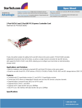
K9N Neo Series
(MS-7260 v1.X) ATX Mainboard
Mainboard Layout
BIOS
JPW1
JUSB2
JUSB3
FDD1
JCI1
IDE1
DIMM1
DIMM2
DIMM3
Winbond
I/O
DIMM4
Top : mouse
Bottom: keyboard
Top : Parallel Port
Bottom:
COM Port
PCI 3
PCI 2
ALC883
PCI 1
PCI _EX3
PCI _EX2
JCD1
JAUD1
CPUFAN1
SYSFAN1
USB ports
T: LAN jack
B: USB ports
T:
M:
B:
Line-In
Line-Out
Mic
PCI _EX1
JIR1
ATX2
LAN
Chip
T:SS-Out
M:CS
B:RS-Out
-Out
BATT
+
nvidia
nForce 550
SATA3 SATA4
JBAT1
JUSB1
SATA1 SATA2
JFP1
JFP2
NBFAN1

1-5
Getting Started
Packing Checklist
SATA Cable
MSI motherboard
MSI Driver/Utility CD
* The pictures are for reference only and may vary from the packing contents of the
product you purchased.
Back IO Shield
User’s Guide
Standard Cable for
IDE Devices
Standard Cable for
Floppy Disk
Power Cable

MS-7260 Mainboard
1-6
MSI Special Feature
Cool’n’Quiet
This utility provides a CPU temperature detection function called Cool’n’Quiet.
Cool’n’Quiet is a special feature designed only for AMD
®
Athlon64 processor, and
with Cool’n’Quiet, the system will be capable of detecting the temperature of the
CPU according to the CPU’s working loading. When the CPU temperature climbs up to
a certain degree, the speed of the system cooling fan will be risen automatically. On
the other hand, the speed of the system cooling fan will slow down instantly when
the CPU temperature descends to its normal degree.
Here the current system status (including Vcore, 3.3V, +5V and 12V) and the current
PC hardware status (such as the CPU & system temperatures and all fans speeds)
are shown on the left and right sides for you to monitor.
When you click the red triangles in the left and right sides, two sub-menus will open
for users to overclock, overspec or to adjust the thresholds of system to send out the
warning messages.
Core Center
The Core Center is a new utility you can find in the CD-ROM disk. The utility is just like
your PC doctor that can detect, view and adjust the PC hardware and system status
during real time operation.

1-7
Getting Started
Left-side: Current system status
In the left sub-menu, you can configure the settings of FSB, Vcore, Memory Voltage
and AGP Voltage by clicking the radio button in front of each item and make it available
(the radio button will be lighted as yellow when selected), use the “+” and “-” buttons
to adjust, then click “OK” to apply the changes. Then you can click “Save” to save
the desired FSB you just configured.
Right-side: PC hardware status during real time operation
In the right sub-menu, here you can configure the PC hardware status such as CPU
& system temperatures and fan speeds. You may use the scroll bars to adjust each
item, then click “OK” to apply the changes. The values you set for the temperatures
are the maximum thresholds for the system warnings, and the values for fan speeds
are the minimum thresholds.
Center-side: Cool’n’Quiet / User mode
Here you may adjust the CPU fan speed. If you choose User mode, you may adjust
the CPU fan speed in 8 different modes, from High Speed to Low speed. If you
choose Cool’n’Quiet, the system will automatically configure an optimal setting for
you.
Important
To ensure that Cool’n’Quiet function
is activated and will be working
properly, it is required to double con-
firm that:
1.Run BIOS Setup, and select H/W
Monitor. Under H/W Monitor,
find Cool’n’Quiet, and set this
item to [Enable].
2.Enter Windows, and select
[Start]->[Settings]->[Control
Pannel]->[Power Options]. Enter
Power Options Properties tag,
and select Minimal Power Man-
agement under Power schemes.

2-1
Hardware Setup
Hardware Setup
Chapter 2
This chapter provides you with the information about
hardware setup procedures. While doing the installation,
be careful in holding the components and follow the
installation procedures. For some components, if you
install in the wrong orientation, the components will not
work properly.
Use a grounded wrist strap before handling computer
components. Static electricity may damage the
components.

2-2
MS-7260 Mainboard
DDRII DIMMs, p.2-6
JFP1, p.2-17
Back Panel
I/O, p.2-10
JPW1,
p.2-8
IDE1, p.2-12
PCI Slots,
p.2-20
JUSB1~3, p.2-16
SATA1~4,
p.2-13
JBAT1, p.2-16
FDD1, p.2-12
PCIE Slots,
p.2-19
CPU, p.2-3
Quick Components Guide
JAUD1, p.2-15
JFP2, p.2-17
JCD1, p.2-14
ATX2,
p.2-8
NBFAN1, p.2-14
SYSFAN1, p.2-14
JIR1, p.2-15
JCI1, p.2-14
CPUFAN1, p.2-14

2-3
Hardware Setup
The mainboard supports AMD
®
Athlon 64/ X2 & Sempron processors. The mainboard
uses a CPU socket called Socket AM2 (940-pin) for easy CPU installation. When you
are installing the CPU, make sure the CPU has a heat sink and a cooling fan
attached on the top to prevent overheating. If you do not have the heat sink and
cooling fan, contact your dealer to purchase and install them before turning on the
computer.
For the latest information about CPU, please visit http://www.msi.com.tw/program/
products/mainboard/mbd/pro_mbd_cpu_support.php
CPU (Central Processing Unit)
Important
1. Overheating will seriously damage the CPU and system. Always make
sure the cooling fan can work properly to protect the CPU from overheating.
2. Make sure that you apply an even layer of heat sink paste (or thermal tape)
between the CPU and the heatsink to enhance heat dissipation.
3. While replacing the CPU, always turn off the ATX power supply or unplug
the power supply’s power cord from the grounded outlet first to ensure the
safety of CPU.
/