Weslo Cadence E-30 Treadmill User manual
- Category
- Treadmills
- Type
- User manual
This manual is also suitable for

USER'S MANUAL
Serial
Number
Decal
Model No. WATL27205.1
Serial No.
CAUTION
Read all precautions and in-
structions in this manual before
using this equipment. Save this
manual for future reference.
QUESTIONS?
If you have questions, or if there
are missing or damaged parts,
we will guarantee complete sat-
isfaction through direct assis-
tance from our factory.
TO AVOID DELAYS, PLEASE
CALL DIRECT TO OUR TOLL-
FREE CUSTOMER HOT LINE.
The trained technicians on our
Customer Hot Line will provide
immediate assistance, free of
charge to you.
CUSTOMER HOT LINE:
800-820-0915
E-mail:
ICON’s Web site:
www.iconfitness.com
Newlife is an authorized dealer of this treadmill in the territory
of mainland China. This treadmill is designed and manufac
-
tured by ICON Health & Fitness, Inc.

TABLE OF CONTENTS
IMPORTANT PRECAUTIONS . . . . . . . . . . . . . . . . . . . . . . . . . . . . . . . . . . . . . . . . . . . . . . . . . . . . . . . . . . . . . . . .3
BEFORE YOU BEGIN . . . . . . . . . . . . . . . . . . . . . . . . . . . . . . . . . . . . . . . . . . . . . . . . . . . . . . . . . . . . . . . . . . . . . .5
ASSEMBLY . . . . . . . . . . . . . . . . . . . . . . . . . . . . . . . . . . . . . . . . . . . . . . . . . . . . . . . . . . . . . . . . . . . . . . . . . . . . . . .6
OPERATION AND ADJUSTMENT . . . . . . . . . . . . . . . . . . . . . . . . . . . . . . . . . . . . . . . . . . . . . . . . . . . . . . . . . . . .10
HOW TO FOLD AND MOVE THE TREADMILL . . . . . . . . . . . . . . . . . . . . . . . . . . . . . . . . . . . . . . . . . . . . . . . . . .16
TROUBLESHOOTING . . . . . . . . . . . . . . . . . . . . . . . . . . . . . . . . . . . . . . . . . . . . . . . . . . . . . . . . . . . . . . . . . . . . .17
CONDITIONING GUIDELINES . . . . . . . . . . . . . . . . . . . . . . . . . . . . . . . . . . . . . . . . . . . . . . . . . . . . . . . . . . . . . . .19
ORDERING REPLACEMENT PARTS . . . . . . . . . . . . . . . . . . . . . . . . . . . . . . . . . . . . . . . . . . . . . . . . . .Back Cover
Note: A PART IDENTIFICATION CHART, an EXPLODED DRAWING, and a PART LIST are attached in the
centre of this manual.
WESLO is a registered trademark of ICON IP, Inc.
2

3
1. It is the responsibility of the owner to ensure
that all users of this treadmill are adequately
informed of all warnings and precautions.
2. Use the treadmill only as described.
3. Place the treadmill on a level surface, with at
least 2.5 m (8 ft.) of clearance behind it and
0.5 m (2 ft.) on each side. Do not place the
treadmill on any surface that blocks air open-
ings. To protect the floor or carpet from dam-
age, place a mat under the treadmill.
4. Keep the treadmill indoors, away from mois-
ture and dust. Do not put the treadmill in a
garage or covered patio, or near water.
5. Do not operate the treadmill where aerosol
products are used or where oxygen is being
administered.
6. Keep children under the age of 12 and pets
away from the treadmill at all times.
7. The treadmill should not be used by persons
weighing more than 115 kg (250 lbs.).
8. Never allow more than one person on the
treadmill at a time.
9. Wear appropriate exercise clothes while using
the treadmill. Do not wear loose clothes that
could become caught in the treadmill. Athletic
support clothes are recommended for both
men and women.
Always wear athletic shoes.
Never use the treadmill with bare feet, wearing
only stockings, or in sandals.
10.
When connecting the power cord (see page
10), plug the power cord into an earthed cir-
cuit. No other appliance should be on the
same circuit. When replacing the fuse, an
ASTA approved BS1362 type should be fitted
to the fuse carrier. A 13 amp fuse should be
used.
11. If an extension cord is needed, use only a 3-
conductor, 1mm
2
(14-gauge) cord that is no
longer than 1.5 m (5 ft.).
12. Keep the power cord away from heated sur-
faces.
13. Never move the walking belt while the power
is turned off. Do not operate the treadmill if
the power cord or plug is damaged, or if the
treadmill is not working properly. (See TROU-
BLESHOOTING on page 17 if the treadmill is
not working properly.)
14. Read, understand, and test the emergency
stop procedure before using the treadmill (see
OPERATION AND ADJUSTMENT).
15. Never start the treadmill while you are stand-
ing on the walking belt. Always hold the
handrails while using the treadmill.
16. The treadmill is capable of high speeds.
Adjust the speed in small increments to avoid
sudden jumps in speed.
17. The pulse sensor is not a medical device.
Various factors, including your movement, may
affect the accuracy of heart rate readings. The
pulse sensor is intended only as an exercise
aid in determining heart rate trends in general.
18. Never leave the treadmill unattended while it
is running. Always remove the key, unplug
the power cord, and move the on/off switch to
the “off” position when the treadmill is not in
use. (See the drawing on page 5 for the loca-
tion of the on/off switch.)
19. Do not attempt to raise, lower, or move the
treadmill until it is properly assembled. (See
ASSEMBLY on page 6 and HOW TO MOVE
THE TREADMILL on page 16.) You must be
able to safely lift 45 pounds (20 kg) to raise,
lower, or move the treadmill.
20. Do not change the incline of the treadmill by
placing objects under the treadmill.
21. When folding or moving the treadmill, make
sure that the frame is securely held by the
lock pin.
22.
Inspect and properly tighten all parts of the
treadmill regularly.
23. Never drop or insert any object into any
opening.
WARNING: T
o reduce the risk of burns, fire, electric shock, or injury to persons, read the
following important precautions and information before operating the treadmill.
IMPORTANT PRECAUTIONS

4
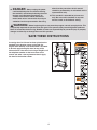
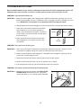
178425
Vertical Latch Warning Decal, Treadmill
A warning decal in Chinese has been placed on the
treadmill in the location shown at the right. An
English decal with the same information is included.
If desired, apply the English decal on top of the
Chinese decal. If the decal is missing or illegible, call
the telephone number on the front cover of this
manual and order a free replacement decal. Apply
the decal in the location shown.
24. DANGER: Always unplug the power
cord immediately after use, before cleaning
the treadmill, and before performing the main-
tenance and adjustment procedures de-
scribed in this manual. Never remove the
motor hood unless instructed to do so by an
a
uthorized service representative. Servicing
other than the procedures in this manual
s
hould be performed by an authorized service
representative only.
25. This treadmill is intended for in-home use
only. Do not use this treadmill in any com-
m
ercial, rental, or institutional setting.
WARNING: Before beginning this or any exercise program, consult your physician. This
is especially important for persons over the age of 35 or persons with pre-existing health problems.
Read all instructions before using. Newlife assumes no responsibility for personal injury or property
damage sustained by or through the use of this product.
SAVE THESE INSTRUCTIONS

5
T
hank you for selecting the new WESLO
®
E
-30 tread-
m
ill. The E-30 treadmill offers an impressive array of
features designed to help you achieve your fitness
goals in the convenience and privacy of your home.
And when you’re not exercising, the unique E-30 tread-
mill can be folded up, requiring less than half the floor
space of conventional treadmills.
For your benefit, read this manual carefully before
using the treadmill. If you have questions after read-
i
ng this manual, see the front cover of this manual. To
h
elp us assist you, please note the product model
number and serial number before contacting us. The
model number of the treadmill is WATL27205.1. The
serial number can be found on a decal attached to the
treadmill (see the front cover of this manual for the lo-
cation).
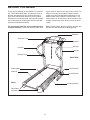
Before reading further, please familiarise yourself with
the parts that are labelled in the drawing below.
BEFORE YOU BEGIN
Handrail
Upright
Storage Latch
Key/Clip
Circuit Breaker
Walking Belt
Walking Platform
Foot Rail
RIGHT SIDE
Rear Roller
Adjustment Bolts
Console
Bookrack
Accessory Tray
On/Off Switch
BACK

ASSEMBLY
A
ssembly requires two persons.
S
et the treadmill in a cleared area and remove all packing materials. Do not
dispose of the packing materials until assembly is completed. Note: The underside of the treadmill walking belt is
coated with high-performance lubricant. During shipping, a small amount of lubricant may be transferred to the
top of the walking belt or the shipping carton. This is a normal condition and does not affect treadmill perfor-
mance. If there is lubricant on top of the walking belt, simply wipe off the lubricant with a soft cloth and a mild,
non-abrasive cleaner.
Assembly requires the included hex keys and your own phillips screwdriver , wire
cutters , and needlenose pliers .
For help identifying the assembly hardware, see the PART IDENTIFICATION CHART in the centre of this
manual. Note: The assembly hardware and other small parts are packaged in separate part bags. Do not
open the part bags until instructed to do so.
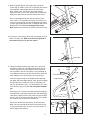
1. Make sure that the power cord is unplugged.
Place the Base (79) in the position shown, with the indi-
cated small holes on top. Next, place the Wheels (63)
into the ends of the Base.
Open part bag A. Attach the Wheels (63) to the Base
(79) with 2” Bolts (61) and Wheel Nuts (64). Make sure
that the Wheel Nuts are on the sides shown; do not
overtighten the Bolts; the Wheels should turn freely.
Attach the four Base Pads (73) to the Base (79) with four
1” Tek Screws (60) (three are shown).
2. Raise the Base (79) to a vertical position, and hold it
near the treadmill Frame (96) as shown. Make sure that
the Wheels (63) are in the indicated position.
Identify the Right Upright (104), which has a large round
hole in the indicated location. Feed the Wire Harness
(65) into the hole and out of the top of the Right Upright.
Make sure that there are two U-nuts (74) in the lower
end of the Right Upright (see drawing 2a). Hold
the Right
Upright against the Base (79) as shown. Make sure that
the Right Upright is oriented so the pivot hole is in the
position shown. Hand tighten two 3” Bolts (58) with two
5/16” Star Washers (57) into the Base and the Right
Upright.
Attach the Left Upright (47) to the Base (79) in the same
way. Note: There is not a wire harness on the left side.
With the help of a second person, raise the Uprights (47,
104) to a vertical position.
60
73
Small Hole
61
73
63
64
79
60
63
60
1
Pivot
Holes
79
58
57
47
58
57
65
63
2a
74
104
6
104
2
61
64
73
96
Round
Hole

7
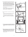
5. Identify the Right Handrail (40), which has a pulse bar
bracket on its left side. Feed the Wire Harness (65) up
into the large bracket on the Right Handrail and out of
the large hole in the left side. (Note: It may be helpful to
use needlenose pliers to pull the Wire Harness out of the
hole.) Remove any nylon ties from the large bracket.
Insert the large bracket on the Right Handrail (40) into
the upper end of the Right Upright (104). Attach the Right
Handrail with two 1” Bolts (43), two 1/4” Washers (44),
two 1/4” Star Washers (45), a 4” Handrail Bolt (78), and a
5/16” Washer (106) as shown.
Do not tighten the Bolts
yet.
See drawing 5a. Insert the included nylon tie through the
indicated hole in the Right Handrail (40). See drawing 5b.
Look into the Right Handrail and make sure that the Wire
Harness (65) is secured to the side shown. Then, tighten
the nylon tie and cut the excess off the end.
Attach the Left Handrail (not shown) in the same way.
Note: You may need to tip the Left Handrail to one side
as you insert the bracket. There is not a wire harness in
the left Upright (not shown).
3. Hold an Upright Spacer (59) against one side of the
Frame (96) as shown. Insert a 4” Frame Bolt (54) into the
i
ndicated hole in the Upright Spacer and the Frame.
Next, tighten a 3/4” Tek Screw (9) into the Upright
S
pacer and the Frame. Then, remove the 4” Frame Bolt.
Repeat this procedure on the other side of the Frame.
Have a second person lift the front end of the Frame
(96). Insert a 4” Frame Bolt (54) with a 3/8” Washer (12)
and a 3/8” Star Washer (55) into the Right Upright (104)
and the right Upright Spacer (59), and tighten the Frame
Bolt into the Frame.
Do not overtighten the Frame
Bolt.
Repeat this procedure on the left side of the Frame.
55
1
2
96
Hole
54
104
9
59
65
43
44
104
45
43
44
45
40
40
78
106
Large
Hole
Large Bracket
Pulse Bar Bracket
5
5a
5b
Tie
Tie
65
40
4. Attach the Latch Housing (46) to the Left Upright (47) with
two 3/4” Screws (38).
Make sure that the large hole in
the Latch Housing is on the side shown.
46
38
47
Large Hole
4
3

Tie
8. Insert the Wire Harness (65) through the indicated nylon tie
on the Console Base (67). Next,
touch the Right Handrail
(40) to discharge any static. See drawing 8a. Insert the
connector on the end of the Wire Harness into the red
socket beneath the Console (69). The connector should
slide easily into the socket and snap into place. If the
connector does not slide easily and snap into place, turn it
and then insert it. IF THE CONNECTOR IS NOT IN
-
SERTED PROPERLY, THE CONSOLE MAY BE DAM-
AGED WHEN THE POWER IS TURNED ON.
Identify the 3/4” Screws (38). Attach the Console Base
(67) to the Right Handrail (40) and the Left Handrail (not
shown) with six 3/4” Screws (only three Screws are
shown). Start all six Screws before tightening them; do
not overtighten the Screws.
Tighten the Pulse Bar Screws (37).
65
67
8
40
8
65
69
38
37
7. Set the console assembly onto the Left and Right
Handrails (13, 40).
Be careful not to pinch the Wire
Harness (65). Tighten two Pulse Bar Screws (37), with
two #10 Star Washers (108), through the brackets on the
Handrails and into the Pulse Bar (39). Do not tighten
the Pulse Bar Screws yet.
7
39
37
40
37
108
108
Console Assembly
13
65
8a
6. Attach the end of the ground wire to the small hole in the
side of the Right Handrail (40) with a Silver Ground
S
crew (66).
6
Ground Wire
66
40

9
12.Make sure that all parts are properly tightened before
you use the treadmill. Note: Extra hardware may be in-
cluded. Keep the included hex keys in a secure place;
the large hex key is used to adjust the walking belt (see
page 18). To protect the floor or carpet, place a mat
under the treadmill.
10. Lower the Handrails (13, 40) until they are touching the
floor.
See drawing 10a. Position the Handrails (13, 40) so the
treadmill Frame (96) is centered between them.
Firmly tighten the four 3” Bolts (58) and the two 4”
Frame Bolts (54).
Be careful not to overtighten the
Bolts.
13
40
40, 13
96
96
Top View
10
10a
58
54
11. Remove the knob from the pin. Make sure that the col-
lar and the spring are on the pin. Insert the pin into the
Latch Housing (46), and then tighten the knob back onto
the pin.
46
Pin
Spring
Knob
Collar
11
38
67
8
4
65
40
9. Press the Wire Harness (65) into the indicated track in
the Console Base (67). (Note: If there is a cylinder on the
W
ire Harness that will not fit into the track, press as
much of the Wire Harness as possible into the track.)
N
ext, insert the excess Wire Harness into the large hole
in the side of the Right Handrail (40). Securely tighten
the nylon tie to prevent the Wire Harness from slip-
ping, and then cut off the end of the nylon tie.
Attach the Access Door (84) to the Console Base (67) with
the 3/4” Screw (38).
See step 5. Tighten, but do not overtighten, the 1”
Bolts (43) and the 4” Handrail Bolts (78).
9
Tie
Track

10
OPERATION AND ADJUSTMENT
THE PRE-LUBRICATED WALKING BELT
Your treadmill features a walking belt coated with high-performance lubricant. IMPORTANT: Never apply sili-
cone spray or other substances to the walking belt or the walking platform. Such substances will deterio-
r
ate the walking belt and cause excessive wear.
HOW TO PLUG IN THE POWER CORD
This product must be earthed.
If it should malfunction or break
down, earthing provides a path of least resistance for electric cur-
rent to reduce the risk of electric shock. This product is equipped
with a power cord having an equipment-earthing conductor and an
earthing plug.
Important: If the power cord is damaged, it must
be replaced with a manufacturer-recommended power cord.
See drawing 1. Plug the indicated end of the power cord into the
socket on the treadmill.
See drawing 2. Plug the power cord into an appropriate outlet that is
properly installed and earthed in accordance with all local codes and
ordinances.
Important: The treadmill is not compatible with
GFCI-equipped outlets.
Socket on Treadmill
1
Outlet
2
DANGER: Improper connection of the equipment-earthing conductor can result in an in-
creased risk of electric shock. Check with a qualified electrician or serviceman if you are in doubt as
to whether the product is properly earthed. Do not modify the plug provided with the product—if it will
not fit the outlet, have a proper outlet installed by a qualified electrician.
Power
Cord

1
1
ETWA27205
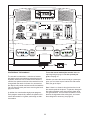
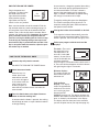
FEATURES OF THE CONSOLE
The treadmill console offers a selection of features
designed to make your workouts more effective and
enjoyable. When the manual mode of the console is
selected, the speed and incline of the treadmill can be
changed with the touch of a button. As you exercise,
the displays will provide continuous exercise feedback.
You can even
measure your heart rate using the hand
-
grip pulse sensor.
In addition, the console offers eight preset programs.
Each program automatically controls the speed and in-
cline of the treadmill as it guides you through an effec-
tive workout.
To use the manual mode of the console, follow the
steps beginning on page 12. To use a preset pro-
gram, see page 14.
Whether you select the manual mode or a preset pro-
gram, you can listen to your favorite FM radio station
while you get in shape.
Note: If there is a sheet of clear plastic on the face of
the console, peel off the plastic. To prevent damage to
the walking platform, wear clean athletic shoes while
using the treadmill. The first time the treadmill is used,
observe the alignment of the walking belt, and center
the walking belt if necessary (see page 18).
Key
Clip

12
HOW TO TURN ON THE POWER
P
lug in the power cord
(see page 11). Next, locate
t
he on/off switch on the
right side of the treadmill
frame near the right up-
right. Make sure that the
switch is in the “on” position.
Next, stand on the foot rails of the treadmill. Find the
clip attached to the key (see the drawing on page 11)
and attach the clip securely to the waistband of your
clothes. Then, insert the key into the console. After a
moment, the displays will light.
Important: In an emer-
gency situation, the key can be pulled from the
console, causing the walking belt to slow to a stop.
Test the clip by carefully taking a few steps back-
ward until the key is pulled from the console. If the
key is not pulled from the console, adjust the posi-
tion of the clip as needed.
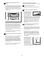
HOW TO USE THE MANUAL MODE
Insert the key fully into the console.
See HOW TO TURN ON THE POWER above.
Select the manual mode.
When the key is in-
serted, the manual
mode will be selected
and a track will appear
in the center of the con-
sole. If you have se-
lected a program, re-
move the key and then reinsert it to select the
manual mode.
Press the Start button or the Speed increase
button
to start
the walking belt.
A moment after the button is pressed, the walking
belt will begin to move at 1 mph. Hold the handrails
and begin walking.
As you exercise, change the speed of the walking
belt as desired by pressing the Speed increase
a
nd decrease buttons. Each time a button is
pressed, the speed setting will change by 0.1
m
ph. If a button is held down, the speed setting
will change in increments of 0.5 mph.
T
o stop the walking belt, press the Stop button.
The Time/Pace display will begin to flash. To
restart the walking belt, press the Start button or
the Speed increase button.
Change the incline of the treadmill as desired.
To change the incline of the treadmill, press the
Incline increase or decrease button. Each time a
button is pressed, the incline will change by 0.5%.
Follow your progress with the track and the
displays.
The track—The track in
the center of the con-
sole represents a dis-
tance of 1/4 mile (400
meters). As you walk or
run on the treadmill, the
indicators around the
track will light in succession until the entire track is
lit. The track will then disappear and the indicators
will again begin to light in succession.
Distance display—
This display shows the
distance that you have
walked or run.
Fat/Cals/Pulse
display—This display
shows the approximate
numbers of
fat calories
and
calories
you have
burned (see FAT
BURNING on page 19). The display will alternate
between
one number and the other every few sec
-
onds, as shown by the indicators in the display.
The display will also show your heart rate when
you use the pulse sensor (see step 6 on page 13).
5
4
3
2
1
On
Position

13
Incline display—This
display shows the in-
c
line level of the tread-
mill.
Time/Pace display—
When the manual
mode is selected, this
display will show the
elapsed time and your
pace (pace is mea-
sured in minutes per
mile or minutes per kilometer). The display will al-
ternate between one number and the other every
few seconds, as shown by the indicators in the
display. When a speed program is selected, the
display will show the time remaining in the program
and your pace.
Speed display—This
display shows the
speed of the walking
belt.
Note: The console can display speed and dis-
tance in either miles or kilometers. The letters
“MPH” or “Km/H” will appear in the Speed display
to show which unit of measurement is selected.
To change the unit of measurement, first select
the console’s information mode by holding down
the Stop button, inserting the key into the console,
and then releasing the
Stop button. An “E” for
English miles or an “M”
for metric kilometers
will appear in the
Incline display. Press
the
Speed increase b
utton to change the unit of
measurement.
While the information
mode is selected, the
Distance display will
show the total number
of miles (or kilometers)
that the walking belt
has moved, and the
T
ime/Pace display will
show the total number
o
f hours that the tread-
mill has been used.
Important: If a “d” ap-
pears in the Speed dis-
play, the console is in
the “demo” mode. This
mode is intended to be
used only while a
treadmill is displayed in a store. While the console
is in the demo mode, the power cord can be
plugged in, the key can be removed from the con-
sole, and the displays will automatically light in a
preset sequence. The buttons on the console will
not operate.
If a “d” appears, press the Speed
decrease button so the “d” disappears.
To exit the information mode at any time, remove
the key from the console.
Measure your heart rate if desired.
Before using the
handgrip pulse
sensor, remove
the sheets of
clear plastic from
the metal con-
tacts. In addition,
make sure that
your hands are clean.
To measure your heart rate, stand on the foot
rails and hold the metal contacts—avoid moving
your hands
. When your pulse is detected, the
heart symbol in the Fat/Cals/Pulse display will
flash, one or two dashes will appear, and then
your heart rate will be shown. For the most accu-
rate heart rate reading,
continue to hold the
contacts for about 15 seconds.
6
Indicator
Contacts

14
Listen to your favorite FM radio station if
desired.
Press the Power button to turn on the radio. Next,
press the Tune buttons to select the desired FM
r
adio station. Then, press the Volume buttons to
adjust the volume of the speakers. Note: A pair of
headphones (not included) can be plugged into the
headphone jack.
If desired, you can save your favorite FM radio sta-
tions in memory. Up to six radio stations can be
saved. First, press the Tune buttons to select a
radio station. Then, press and hold one of the six
Memory buttons for several seconds until a series
of tones sounds. The radio station will then be
saved. To select the radio station again, press the
same Memory button.
If radio reception is poor, reposition the treadmill
until the reception is improved.
When you are finished exercising, remove the
key.
Step onto the foot rails, press the Stop button, and
adjust the incline of the treadmill to the lowest
level. The incline must be at the lowest level
when the treadmill is raised to the storage po
-
sition or the treadmill will be damaged. Next,
remove the key from the console and put the key
in a secure place.
When you are finished using the treadmill, switch
the on/off switch to the “off” position.
H
OW TO USE A PRESET PROGRAM
I
nsert the key into the console.
S
ee HOW TO TURN ON THE POWER on page
12.
S
elect one of the eight preset programs.
Press the Program but-
ton repeatedly until the
desired preset program
is selected. When a pro-
gram is selected, the
maximum incline setting
of the program will flash for several seconds in the
Incline display, and the maximum speed setting of
the program will flash for several seconds in the
Speed display. The Time/Pace display will show
how long the program will last. A profile of the
speed settings of the program will scroll across
the matrix.
Press the Start button or the Speed increase
button to start the program.
A moment after the button is pressed, the tread-
mill will automatically adjust to the first speed and
incline settings of the program. Hold the handrails
and begin walking.
Each program consists of either 30 or 60 one-
minute segments. One speed setting and one in-
cline setting are programmed for each segment.
Note: The same speed setting and/or incline set-
ting may be programmed for two or more consec-
utive segments.
The speed setting for the
first segment will be
shown in the flashing
Current Segment column
of the matrix. (The in-
cline settings are not
shown in the matrix.)
The speed settings for
the next three
segment
s
will be shown in the columns at the right.
3
2
1
8
7
Power
Button
Memory
Buttons
Headphone
Jack
Current Segment
Column

15
When only three seconds remain in the first seg-
ment of the program, both the Current Segment
c
olumn and the column to the right will flash, and
a series of tones will sound. If the speed and/or in-
c
line of the treadmill is about to change, the
Incline display and/or the Speed display will flash
to alert you. When the first segment ends,
all
speed settings in the matrix will move one column
to the left
. The speed setting for the second seg-
ment will then be shown in the flashing Current
Segment column, and the treadmill will automati-
cally adjust to the speed and incline settings for
the second segment. Note: If all of the indicators
in the Current Segment column are lit after the
speed settings have moved to the left,
the speed
settings may move downward
so that only the
highest indicators appear in the matrix. If some in-
dicators in the Current Segment column are not lit
when the speed settings move to the left again,
the speed settings will move back up.
The program will continue in this way until the
speed setting for the last segment is shown in the
Current Segment column and the last segment
ends. The walking belt will then slow to a stop.
If the speed or incline setting is too high or too low
at any time during the program, you can manually
override the setting by pressing the Speed or
Incline buttons. Every few times a Speed button is
pressed, an additional indicator will appear or dis-
appear in the Current Segment column. (If any of
the columns to the right of the Current Segment
column have the same number of indicators as the
Current Segment column, an additional indicator
may appear or disappear in those columns as
w
ell.)
N
ote: When the next segment of the pro-
gram begins, the treadmill will automatically
a
djust to the speed and incline settings for the
next segment.
To stop the program at any time, press the Stop
button. The Time/Pace display will begin to flash.
To restart the program, press the Start button or
the Speed increase button. The walking belt will
begin to move at 1 mph. When the next segment
of the program begins, the treadmill will automati-
cally adjust to the speed and incline settings for the
next segment.
Follow your progress with the track and the
displays.
See step 5 on page 12.
Measure your heart rate if desired.
See step 6 on page 13.
Listen to the radio if desired.
See step 7 on page 14.
When you are finished exercising, remove the
key.
See step 8 on page 14.
7
6
5
4

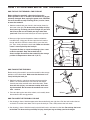
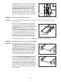
HOW TO FOLD AND MOVE THE TREADMILL
HOW TO FOLD THE TREADMILL FOR STORAGE
Before folding the treadmill, adjust the incline to the
lowest position. If this is not done, the treadmill may be per-
m
anently damaged. Next, unplug the power cord. CAUTION:
You must be able to safely lift 20 kg (45 lbs.) to raise, lower,
or move the treadmill.
1. Hold the treadmill with your hands in the location shown by
the arrow at the right.
To decrease the possibility of injury,
bend your legs and keep your back straight. As you raise
the frame, make sure to lift with your legs rather than
your back.
Raise the frame halfway to the vertical position.
2. Move your right hand to the position shown and hold the
treadmill firmly. Using your left hand, pull the latch knob to
the left and hold it. Raise the frame until it is past the latch
pin. Then, slowly release the latch knob.
Make sure that the
frame is securely held by the latch pin.
To protect the floor or carpet from damage, place a mat
under the treadmill. Keep the treadmill out of
direct sunlight. Do not leave the treadmill in the storage
position in temperatures above 30° C (85° F).
HOW TO MOVE THE TREADMILL
Before moving the treadmill, convert the treadmill to the storage
position as described above.
Make sure that the frame is se-
curely held by the latch pin.
1. Hold the handrails, and place one foot against one of the
wheels. Tilt the treadmill back until it rolls on the wheels.
Carefully move the treadmill to the desired location.
To re
-
duce the risk of injury, use extreme caution while mov-
ing the treadmill. Do not move the treadmill over an un-
even surface.
2. Place one foot against one of the wheels, and carefully lower
the treadmill to the storage position.
HOW TO LOWER THE TREADMILL FOR USE
1.
See drawing 2 above. Hold the upper end of the treadmill with your right hand. Pull the latch knob to the left
and hold it. Pivot the frame down until it is past the latch pin. Then, slowly release the latch knob.
2. See drawing 1 above. Hold the frame firmly with both hands, and lower it to the floor. Do not drop the frame
to the floor. To decrease the possibility of injury, bend your legs and keep your back straight.
Engaged
Frame
Latch
Knob
Latch Pin
Base
Wheel
Handrails
16

17
TROUBLESHOOTING
Most treadmill problems can be solved by following the steps below. Find the symptom that applies, and
follow the steps listed. If further assistance is needed, please see the front cover of this manual.
PROBLEM: The power does not turn on
SOLUTION: a. Make sure that the power cord is plugged into a properly earthed outlet (see page 10). If an ex-
tension cord is needed, use only a 3-conductor, 1mm
2
(14-gauge) cord that is no longer than 1.5 m
(5 ft.).
IMPORTANT: The treadmill is not compatible with GFCI-equipped outlets.
b. After the power cord has been plugged in, make sure that the key is fully inserted into the console.
c. Check the circuit breaker located on the treadmill
near the power cord. If the switch protrudes as
shown, the circuit breaker has tripped. To reset the
circuit breaker, wait for five minutes and then press
the switch back in.
d. Check the on/off switch located on the treadmill
near the power cord. The switch must be in the
“on” position.
PROBLEM: The power turns off during use
SOLUTION: a. Check the circuit breaker located on the treadmill near the power cord (see c. above). If the cir-
cuit breaker has tripped, wait for five minutes and then press the switch back in.
b. Make sure that the power cord is plugged in. If the power cord is plugged in, unplug it, wait for
five minutes, and then plug it back in.
c. Remove the key from the console. Reinsert the key fully into the console.
d. Make sure that the on/off switch is in the “on” position (see d. above).
e. If the treadmill still will not run, please see the front cover of this manual.
PROBLEM: The displays of the console do not function properly
SOLUTION:
a. Remove the key from the console and UNPLUG THE
POWER CORD
.
Remove the four 3/4” Tek Screws
(9) from the Hood (1), and carefully remove the Hood.
9
1
a
Tripped
c
Reset
On
Position
d

18
Locate the Reed Switch (16) and the Magnet (10) on
the left side of the Pulley (101). Turn the Pulley until
t
he Magnet is aligned with the Reed Switch. M
ake
sure that the gap between the Magnet and the
R
eed Switch is about 3 mm (1/8 in.).
I
f necessary,
loosen the indicated 3/4” Tek Screws (9), move the
Reed Switch slightly, and then retighten the Screw.
Reattach the Hood (not shown), and run the treadmill
for a few minutes to check for a correct speed read-
ing.
PROBLEM: The walking belt slows when walked on
SOLUTION:
a. If an extension cord is needed, use only a 3-conductor, 1mm
2
(14-gauge) cord that is no longer
than 1.5 m (5 ft.).
b. If the walking belt is overtightened, treadmill perfor-
mance may decrease and the walking belt may be-
come damaged. Remove the key and
UNPLUG THE
POWER CORD
. Using the hex key, turn both rear
roller bolts counterclockwise, 1/4 of a turn. When the
walking belt is properly tightened, you should be able
to lift each edge of the walking belt 8 to 10 cm (3 to 4
in.) off the walking platform. Be careful to keep the
walking belt centred. Then, plug in the power cord, in-
sert the key, and run the treadmill for a few minutes.
Repeat until the walking belt is properly tightened.
c. If the walking belt still slows when walked on, please see the front cover of this manual.
PROBLEM: The walking belt is off-centre or slips when walked on
SOLUTION: a. If the walking belt is off-centre, remove the key and
UNPLUG THE POWER CORD. If the walking belt
has shifted to the left, use the hex key to turn the left
rear roller bolt clockwise 1/2 of a turn; if the walking
belt has shifted to the right, turn the left rear roller
bolt counterclockwise 1/2 of a turn. Be careful not to
overtighten the walking belt. Then, plug in the power
cord, insert the key, and run the treadmill for a few
minutes. Repeat until the walking belt is centred.
b.
If the walking belt slips when walked on, first remove
the key and
UNPLUG THE POWER CORD. Using
the hex key, turn both rear roller bolts clockwise, 1/4
of a turn. When the walking belt is correctly tightened,
you should be able to lift each edge of the walking
belt 8 to 10 cm (3 to 4 in.) off the walking platform. Be
careful to keep the walking belt centred. Then, plug in
the power cord, insert the key, and walk on the tread
-
mill for a few minutes. Repeat until the walking belt is
properly tightened.
b
a
Rear Roller Bolts
8–10 cm
b
10
16
9
Top View
3
mm
101

19
CONDITIONING GUIDELINES
The following guidelines will help you to plan your ex-
ercise program. For more detailed exercise informa-
tion, obtain a reputable book or consult your physician.
EXERCISE INTENSITY
Whether your goal is to burn fat or to strengthen your
cardiovascular system, the key to achieving the
desired results is to exercise with the proper intensity.
The proper intensity level can be found by using your
heart rate as a guide. The chart below shows recom-
mended heart rates for fat burning and aerobic exercise.
To find the proper heart rate for you, first find your age
near the bottom of the chart (ages are rounded off to
the nearest ten years). Next, find the three numbers
above your age. The three numbers define your “train-
ing zone.” The lower two numbers are recommended
heart rates for fat burning; the higher number is the
recommended heart rate for aerobic exercise.
Fat Burning
To burn fat effectively, you must exercise at a relatively
low intensity level for a sustained period of time.
During the first few minutes of exercise, your body
uses easily accessible
carbohydrate calories
for en-
ergy. Only after the first few minutes does your body
begin to use stored
fat calories
for energy. If your goal
is to burn fat, adjust the speed and incline of the tread-
mill until your heart rate is near the lowest number in
y
our training zone.
For maximum fat burning, adjust the speed and incline
of the treadmill until your heart rate is near the middle
number in your training zone.
Aerobic Exercise
If your goal is to strengthen your cardiovascular sys-
tem, your exercise must be “aerobic.” Aerobic exercise
is activity that requires large amounts of oxygen for
prolonged periods of time. This increases the demand
on the heart to pump blood to the muscles, and on the
lungs to oxygenate the blood. For aerobic exercise,
adjust the speed and incline of the treadmill until your
heart rate is near the highest number in your training
zone.
WORKOUT GUIDELINES
Each workout should include the following three parts:
A Warm-up—Start each workout with 5 to 10 minutes
of stretching and light exercise. A proper warm-up in-
creases your body temperature, heart rate and circula-
tion in preparation for exercise.
Training Zone Exercise—After warming up, increase
the intensity of your exercise until your pulse is in your
training zone for 20 to 60 minutes. (During the first few
weeks of your exercise program, do not keep your
pulse in your training zone for longer than 20 minutes.)
Breathe regularly and deeply as you exercise—never
hold your breath.
A Cool-down—Finish each workout with 5 to 10 min
-
utes of stretching to cool down. This will increase the
flexibility of your muscles and will help prevent post-ex-
ercise problems.
EXERCISE FREQUENCY
To maintain or improve your condition, complete three
workouts each week, with at least one day of rest be-
tween workouts. After a few months, you may com-
plete up to five workouts each week if desired. The key
to success is to make exercise a regular and enjoyable
part of your everyday life.
WARNING: Before beginning this
or any exercise program, consult your physi-
c
ian. This is especially important for individu-
als over the age of 35 or individuals with pre-
existing health problems.
The pulse sensor is not a medical device.
Various factors, including the user’s move-
ment, may affect the accuracy of heart rate
readings. The pulse sensor is intended only as
an exercise aid in determining heart rate trends
in general.

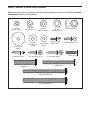
Wheel Nut (64)–2
1” Bolt (43)–4
Silver Ground
Screw (66)–1
3/4” Screw (38)–9
1/4” Washer
(44)–4
1/4” Star
Washer (45)–4
3/8” Star
Washer (55)–2
3” Bolt (58)–4
4” Handrail Bolt (78)–2
5/16” Star
Washer (57)–4
2” Bolt (61)–2
Pulse Bar Screw (37)–2
4” Frame Bolt (54)–2
3/8” Washer
(12)–2
#10 Star
Washer (108)–2
3/4” Tek Screw (9)–2
2
5/16” Washer
(106)–2
1” Tek Screw (60)–4
R
emove this chart and use it to identify small parts during assembly. Save this chart and the EXPLODED
DRAWING/PART LIST for future reference.
PART IDENTIFICATION CHART
Page is loading ...
Page is loading ...
Page is loading ...
-
 1
1
-
 2
2
-
 3
3
-
 4
4
-
 5
5
-
 6
6
-
 7
7
-
 8
8
-
 9
9
-
 10
10
-
 11
11
-
 12
12
-
 13
13
-
 14
14
-
 15
15
-
 16
16
-
 17
17
-
 18
18
-
 19
19
-
 20
20
-
 21
21
-
 22
22
-
 23
23


Weslo Cadence E-30 Treadmill User manual
- Category
- Treadmills
- Type
- User manual
- This manual is also suitable for
Ask a question and I''ll find the answer in the document
Finding information in a document is now easier with AI
Related papers
-
Weslo Cadence S6 Treadmill User manual
-
Weslo WATL14906.0 User manual
-
Weslo Cadence 900 Treadmill User manual
-
-
-
-
-
-
-
Other documents
-
HealthRider HATL51205.0 User manual
-
NordicTrack 1900i Treadmill User manual
-
-
ProForm PETL50133 User manual
-
NordicTrack NETL15520 User manual
-
-
Gold's Gym 685T User manual
-
ProForm PFTL51230 User manual
-
NordicTrack 3100 R NTL15920 User manual
-