Page is loading ...

51001
Rev 51001-20090526
10006 Santa Fe Springs Road
Santa Fe Springs, CA 90670 USA
Made in China
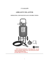
10 gallon
ABRASIVE BLASTER
SAVE THESE INSTRUCTIONS
Important Safety
Instructions are included in
this manual
Owner’s Manual and Operating Instructions


Table of Contents
Introduction ..................................... 1
Accessories ................................................ 1
This Booklet .............................................. 1
Manual Conventions ......................... 2
Safety Rules ...................................... 3
Assembly .......................................... 5
Abrasive Safety Trigger Assembly ............ 5
Attach the handles .................................... 5
Attach the wheels ...................................... 6
Abrasive Selection .................................... 6
Operation ......................................... 7
Loading Abrasive ...................................... 7
To Start Abrasive Blasting ........................ 7
Abrasive flow adjustment ..................... 7
To Stop Blasting ........................................ 8
Releasing pressure from the tank ............ 8
Maintenance ..................................... 9
Specifications ................................. 10
Safety Trigger Parts List ......................... 11
Tank parts diagram ................................. 12
Parts List ................................................. 13
Warranty ........................................ 14
Warranty Qualifications ......................... 14
Repair/Replacement Warranty .............. 14
Do not return the unit to the place of
purchase .................................................. 14
Warranty Exclusions ............................... 14
Normal Wear ....................................... 14
Installation, Use and Maintenance ..... 14
Other Exclusions ................................. 14
Limits of Implied Warranty and
Consequential Damage ........................... 14
Contact Information ............................... 15
Address ................................................ 15
Customer Service ................................ 15
Technical Service ................................. 15
Notes .............................................. 16


Introduction
Rev 51001-20090526 1
Introduction
Congratulations on your purchase of a
Champion Power Equipment abrasive
blaster. CPE designs and builds abrasive
blasters to strict specifications. With proper
use and maintenance, this abrasive blaster
will bring years of satisfying service.
This Owner’s Manual contains important
safety instructions and information. SAVE
THESE INSTRUCTIONS FOR FUTURE
REFERENCE.
Accessories
Champion Power Equipment manufactures
and sells accessories designed to help you
get the most from your purchase. To find out
more about our products, please visit our
web site at
www.championpowerequipment.com
This Booklet
Every effort has been made to ensure the
accuracy and completeness of the
information in this manual. We reserve the
right to change, alter and/or improve the
product and this document at any time
without prior notice.
Record the model and serial numbers as well as date and place of purchase for future reference.
Have this information available when ordering parts and when making technical or warranty
inquiries.
Champion Power Equipment Support
1-877-338-0999
Model Number
51001
Serial Number
Date of Purchase
Purchase Location

Manual Conventions
2 Rev 51001-20090526
Manual Conventions
This manual uses the following symbols to
help differentiate between different kinds of
information. The safety symbol is used with
a key word to alert you to potential hazards
in operating and owning power equipment.
Follow all safety messages to avoid or reduce
the risk of serious injury or death.
DANGER
DANGER indicates an imminently hazardous
situation which, if not avoided,
will
result in death
or serious injury.
WARNING
WARNING indicates a potentially hazardous
situation which, if not avoided,
could
result in
death or serious injury.
CAUTION
CAUTION indicates a potentially hazardous
situation which, if not avoided,
may
result in
minor or moderate injury.
CAUTION
CAUTION used without the safety alert symbol
indicates a potentially hazardous situation which,
if not avoided,
may
result in property damage.
NOTE
If you have questions regarding your winch, we
can help. Please call our help line at 1-877-338-
0999.

Safety Rules
Rev 51001-20090526 3
Safety Rules
WARNING
Do not use any sand or silica based abrasives
with this tool. Silica based abrasives have been
linked to severe respiratory disease. Always use
OSHA recommended abrasives.
CAUTION
Know your tool. Read this manual carefully.
Learn the tool’s applications and limitations, as
well as potential hazards specific to it.
CAUTION
Do not expose tool to moisture. Don’t use this
tool in damp or wet locations. Keep out of rain.
CAUTION
Keep work area clean and well lit. Cluttered or
dark work areas invite accidents.
WARNING
Keep children away. All children should be kept
away from the work area. Never let a child
handle a tool without strict adult supervision.
WARNING
Use safety equipment. Eye protection should be
worn at all times when operating this tool. Use
ANSI approved safety glasses. Everyday
eyeglasses are NOT safety glasses. Dust mask,
non-skid safety shoes, hard hat, or hearing
protection should be used in appropriate
conditions.
WARNING
Wear proper apparel. Loose clothing, gloves,
neckties, rings, bracelets, or other jewelry may
present a potential hazard when operating this
tool. Please keep all apparel clear of the tool.
WARNING
Don’t overreach. Keep proper footing and
balance at all times when operating this product.
WARNING
Always disconnect the tool from air supply and
release pressure from the tank before making
any adjustments, storing, servicing, or changing
accessories. Such preventative safety measures
reduce the risk of starting the tool accidentally.
WARNING
Use clamps or other practical means to secure
and support the work piece to a stable platform.
Holding the work by hand or against your body
may lead to a loss of control.
WARNING
Do not force tool. Use the correct tool for your
application. The correct tool will do the job better
and safer at the rate for which it was designed.
WARNING
Check for damage. Check your tool regularly. If
part of the tool is damaged it should be carefully
inspected to make sure that it can perform its’
intended function correctly. If in doubt, the part
should be repaired. Refer all servicing to a
qualified technician. Consult your dealer for
advice.

Safety Rules
4 Rev 51001-20090526
WARNING
Keep away from flammables. Do not attempt to
operate this tool near flammable materials or
combustibles. Failure to comply may cause
serious injury or death.
CAUTION
Always check to make sure that the trigger is not
on before connecting blaster to air supply. Tool
may cause damage to property or person if
plugged in while on.
CAUTION
Store idle tools out of the reach of children and
untrained persons. Tools may be dangerous in
the hands of untrained users.
CAUTION
Drain water trap periodically during use. Do not
allow moisture to fill more than 1/2 the water
trap bowl. Do not leave water standing in water
trap when done with work.
WARNING
Do not allow abrasive blaster to sit pressurized
while unattended or not in use.
CAUTION
Make sure all equipment is rated to the
appropriate capacity. Make sure regulator is set
at no higher than 125 psi.
CAUTION
Periodically check the abrasive medium delivery
equipment. Valves, hoses and nozzles that carry
the abrasive medium after it leaves the pressure
tank are subjected to the abrasive blasting action
so will wear out more quickly than other
components.
WARNING
Maintain correct air pressure whenever working.
Do not allow pressure to exceed 125 psi. If the
safety valve does not release excess air pressure,
stop all work and release pressure from the tank
(see "Releasing Pressure from the Tank" section).

Assembly
5
Assembly
Your abrasive blaster requires some
assembly.
If you have any questions regarding the
assembly of your abrasive blaster, call our
help line at 1-877-338-0999. Please have
your serial number and model number
available.
Remove all contents from the shipping
carton and prepare a clean, flat working
surface for assembly.
Abrasive Safety Trigger
Assembly
1. Locate the Abrasive Safety Trigger, the
Abrasive Hose (24) and the two Hose
Clamps (23).
2. Slide one Hose Clamp onto each end of
the Abrasive Hose. Do not tighten yet.
3. Slide one end of the Abrasive Hose onto
the Abrasive Safety Trigger Hose
Adaptor (49) and firmly tighten Hose
Clamp.
4. Slide the other end of the Abrasive hose
onto the Abrasive Outlet Manifold (22)
and firmly tighten Hose Clamp.
Attach the handles
1. Locate the two Handle Bars (06), the
two Handle Grips (07), the four Screws
(08), the four nuts (09), and the four
Washers (50).
2. Lay the Abrasive Blast Tank on a flat
level surface (such as a workbench or
table top), with the handlebar mounting
brackets facing up.
3. If Handle Grips are not already installed
on the Handle Bars, slide them onto the
Handle Bars, with the finger holds
towards the bottom of each Handle Bar.
4. Handle Bars are labeled “LEFT” and
“RIGHT.” Align the holes in the left
Handle Bar with the Handle Bar
Mounting Brackets on the left side of
Blast Tank.
5. Place a Washer (50) onto each of the
four handle bar mounting Screws (08).
Insert a Screw through each of the holes
in Handle Bar and Handle Bar
Mounting Brackets.
6. Place a nut onto each of the Screws and
firmly tighten in place with a wrench.
7. Repeat steps 4 – 6 for right Handle Bar.

Assembly
6 Rev 51001-20090526
Attach the wheels
1. Locate the two Wheels (02), the three
Cotter Pins (03), the Wheel Axle (05),
four Wheel Washers (51), and the Front
Foot (04).
2. Slide the Wheel Axle (05) through the
axle holes located at the bottom of the
Handle Bars.
3. Slide a Wheel Washer (51) onto each end
of the wheel axle.
4. Place a Wheel (02) onto each end of the
Wheel Axle then slide a Wheel Washer
onto the axle.
5. Insert a Cotter Pin(03) through the
holes in each end of the Wheel Axle and
bend them so the wheels cannot slide off
the Wheel Axle.
6. Roll Abrasive Blast Tank over so that
Handle Bars are now facing down.
7. Align the holes of the Front Foot (04)
with the holes in the foot mount on the
front side of the Blast Tank.
8. Insert a Cotter Pin (03) through the
holes and bend it so the Front Foot
cannot slide off the foot mount.
Abrasive Selection
The kind of abrasive you choose will greatly
influence the amount of time needed to
clean a given surface area. Abrasive
materials include garnet, glass beads and
others. For best results, use 80 grit abrasive
or finer. Do not exceed 80 grit media size.
Make sure that the abrasive you use is
thoroughly dry. Damp abrasive can cause
clogging of your abrasive blaster.
While you may reuse abrasive, remember
that abrasive does wear out. After use,
abrasive becomes smoother and rounder,
thus reducing abrasive effectiveness.
Reusing abrasive may also cause clogging
due to debris contained in the mixture from
prior use.

Operation
Rev 51001-20090526 7
Operation
WARNING
Always wear your hood, dust mask and heavy
duty canvas gloves when operating the abrasive
blaster.
WARNING
Before operating your abrasive blaster, inspect
each connection, double checking to make sure
that all are tight and properly sealed.
Loading Abrasive
1. Check to make sure the abrasive is dry
and clean so that it does not clog the
unit.
2. Close the brass Air Supply Valve (18) by
turning it to the vertical position.
3. To release the pressure from the Tank,
press Safety Trigger until air stops.
4. Make sure the Pressure Gauge (15) reads
“0”.
5. Remove the Filler Cap (12).
6. Using the Funnel (29), pour the selected
abrasive media into the tank (1). Do not
fill the tank more than 3/4 full. If
humidity in your region is 90% or more,
only fill the tank half full and check the
water trap (17) more frequently.
7. Close the Filler Cap securely, assuring o-
ring is in place.
NOTE
Place your air compressor in another room
to prevent damage to it.
To Start Abrasive Blasting
NOTE
Start with all valves in the closed position.
Following the instructions below will help prevent
the formation of clogs in the abrasive hose,
outlet manifold and the safety trigger.
1. Connect air compressor to the Inlet
Connector (19).
2. Start compressor and open Air Supply
Valve (18).
3. Open Throttling Valve (18A).
4. Check for leaks at the Filler Cap and
along all hoses and fittings as the system
pressurizes. If leaks are observed,
release the pressure from the tank and
repair immediately.
5. Point Safety Trigger in a safe direction
away from people, pets or anything
around you that may be damaged by
direct or indirect abrasive spray.
6. Press and hold Safety Trigger until air is
flowing through the trigger.
7. With the Safety Trigger open, slowly
open the Abrasive Control Valve (18B)
until abrasive material begins to flow
out of the Safety Trigger.
8. Adjust the Abrasive Control Valve (18B)
until the desired amount of abrasive
material is flowing through the Safety
Trigger.
9. Begin blasting.
Abrasive flow adjustment
Choose a larger nozzle for a broader spray
pattern. Choose a smaller nozzle for more
focused abrasive blasting.
1. Adjust air pressure with the Brass
Throttling Valve (18A). Adjust abrasive
flow with Abrasive Control Valve (18B).
2. Watch for abrasive clogging. Release
pressure from the tank if necessary and
replace the abrasive with drier or
cleaner abrasive.

Operation
8 Rev 51001-20090526
To Stop Blasting
1. While continuing to press and hold the
Safety Trigger, turn the Abrasive Control
Valve (18B) to the closed position (this is
to prevent any clogging.)
2. When you notice only air (no abrasive)
is coming out of the Safety Trigger, you
can stop the air flow by releasing the
trigger. By doing this you are ensuring a
clean and clog-free manifold, hose, and
safety trigger.
Releasing pressure from the
tank
1. When finished blasting, point Safety
Trigger in a safe direction away from
people, pets or anything around you that
may be damaged by direct or indirect
abrasive spray.
2. Press and hold the Safety Trigger to
expel any remaining abrasive material
from the Abrasive Hose (24).
3. Close the Abrasive Control Valve (18B).
4. Release pressure on the Safety Trigger.
5. Close the Throttling Valve (18A) and the
Air Supply Valve (18).
6. Disconnect air supply hose from
abrasive blaster.
7. Press the Safety Trigger until air stops
flowing and Pressure Gauge (15) reads
“0".

Maintenance
Rev 51001-20090526 9
Maintenance
The owner/operator is responsible for all
periodic maintenance.
WARNING
Never operate a damaged or defective abrasive
blaster.
WARNING
Improper maintenance will void your warranty.
NOTE
For service or parts assistance, contact our help
line at 1-877-338-0999.
1. Keep your abrasive blaster clean, and
protect it from damage.
2. Release pressure from the tank after
each use.
3. When initially pressurizing, check for
leaks at the tank top and at all hoses and
fittings. Leaking joints may be repaired
by replacing worn or damaged parts and
teflon tape at joints.
4. Check for worn abrasive hose and
fittings. The Abrasive Control Valve,
manifold, and all parts after the abrasive
is ejected from the tank are subject to
rapid wear due to the flow of abrasive.
Watch especially for leaks, blistering,
bulging or thinness of the hose. Replace
any parts which appear worn.

Specifications
10 Rev 51001-20090526
Specifications
Tank Volume 10 gallons
Hose Length 8 feet
Working pressure 60-125 PSI
Air consumption 6-25 CFM
Weight 41 lbs
Height 34 inches (863mm)
Width 17 inches (115.5 mm)
Length 11 inches (415 mm)

Specifications
11
Safety Trigger Parts List
Item Part Number Description Qty
31 SB9008-0031 Body Upper 1
32 SB9008-0032 Body Lower 1
33 SB9008-0033 Metal Pipe 1
34 SB9008-0034 Intake Connector 1
35 SB9008-0035 Adaptor 1
36 SB9008-0036 Gasket 1
37 SB9008-0037 Ceramic Nozzle 4
38 SB9008-0038 Rubber Adaptor 4
39 SB9008-0039 Nozzle Cap Nut 1
40 SB9008-0040 Screw ST 4.2 x 16 4
41 SB9008-0041 Screw ST 4.2 x 12 2
42 SB9008-0042 On/Off Control Lever 1
43 SB9008-0043 Spring Pin 1
44 SB9008-0044 Spring 1
45 SB9008-0045 Rubber Pad 1
46 SB9008-0046 Screw M3 x 25 1
47 SB9008-0047 Hard Alloy Pad 1
48 SB9008-0048 Nut M3 1
49 SB9008-0049 Hose Adaptor 1

Specifications
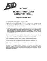
12
Tank parts diagram

Specifications
13
Parts List
Item
Part Number Description Qty
1
SB9008-0001 Tank 1
2
SB9008-0002 Wheels 2
3
SB9008-0003 Cotter Pins 3
4
SB9008-0004 Front Foot 1
5
SB9008-0005 Wheel Axle 1
6
SB9008-0006 Handle Bars 2
7
SB9008-0007 Handle Grips 2
8
SB9008-0008 Pan Screws 4
9
SB9008-0009 Hex Nuts 4
10
SB9008-0010 Safety Valve 1
11
SB9008-0011 O-Ring 1
12
SB9008-0012 Tank Filler Cap 1
13
SB9008-0013 Joint Pipe 1
14
SB9008-0014 Intake Manifold 1
15
SB9008-0015 Pressure Gauge 1
16
SB9008-0016 3/8" Nipple Connectors 5
17
SB9008-0017 Water Trap 1
18
SB9008-0018 3/8" Brass Air Supply Valve 1
18A
SB9008-0018A 3/8" Brass Throttling Valve 1
18B
SB9008-0018B 3/8" Steel Abrasive Control Valve 1
19
SB9008-0019 Inlet Connector 1
20
SB9008-0020 Nipple Connector 1
21
SB9008-0021 Air Hose 1
22
SB9008-0022 Abrasive Outlet Manifold 1
23
SB9008-0023 Hose Clamps 2
24
SB9008-0024 Abrasive Hose 1
29
SB9008-0029 Funnel 1
30
SB9008-0030 Hood 1
30A
SB9008-0030A Lens for Hood 1
50
SB9008-0050 Washer 4
51
SB9008-0051 Wheel Washer 4
For parts 31-49, please refer to safety trigger parts list on page 11

Warranty
14 Rev 51001-20090526
Warranty
CHAMPION POWER EQUIPMENT
ONE YEAR LIMITED WARRANTY
Effective September 1, 2006. Replaces all
undated warranties and all warranties dated
before September 1, 2006.
Warranty Qualifications
Champion Power Equipment (CPE) will
register this warranty upon receipt of your
Warranty Registration Card and a copy of
your sales receipt from one of CPE's retail
locations as proof of purchase.
Please submit your warranty registration
and your proof of purchase within ten (10)
days of the date of purchase.
Repair/Replacement
Warranty
CPE warrants to the original purchaser that
the mechanical and electrical components
will be free of defects in material and
workmanship for a period of one (1) year
from the original date of purchase (90 days
for commercial & industrial use).
Transportation charges on product
submitted for repair or replacement under
this warranty are the sole responsibility of
the purchaser. This warranty only applies to
the original purchaser and is not
transferable.
Do not return the unit to the
place of purchase
Contact CPE's Technical Service and CPE
will troubleshoot any issue via phone or e-
mail. If the problem is not corrected by this
method, CPE will, at its option, authorize
evaluation, repair or replacement of the
defective part or component at a CPE
Service Center. CPE will provide you with a
case number for warranty service. Please
keep it for future reference. Repairs or
replacements without prior authorization, or
at an unauthorized repair facility, will not be
covered by this warranty.
Warranty Exclusions
This warranty does not cover the following
repairs and equipment:
Normal Wear
Abrasive blasters need periodic parts and
service to perform well. This warranty does
not cover repair when normal use has
exhausted the life of a part or the equipment
as a whole.
Installation, Use and
Maintenance
This warranty will not apply to parts and/or
labor if this abrasive blaster is deemed to
have been misused, neglected, involved in an
accident, abused, loaded beyond the tank’s
limits, modified, installed improperly or
connected incorrectly to any electrical
component. Normal maintenance is not
covered by this warranty.
Other Exclusions
This warranty excludes:
Cosmetic defects such as paint, decals, etc.
Accessory parts such as storage covers.
Failures due to acts of God and other force
majeure events beyond the manufacturer’s
control.
Problems cause by parts that are not original
Champion Power Equipment parts.
Limits of Implied Warranty
and Consequential Damage
Champion Power Equipment disclaims any
obligation to cover any loss of time, use of
this product, freight, or any incidental or
consequential claim by anyone from using
this winch. THIS WARRANTY IS IN LIEU
OF ALL OTHER WARRANTIES, EXPRESS
OR IMPLIED, INCLUDING WARRANTIES
OF MERCHANTABILITY OR FITNESS FOR
A PARTICULAR PURPOSE
A unit provided as an exchange will be
subject to the warranty of the original unit.
The length of the warranty governing the
exchanged unit will remain calculated by
reference to the purchase date of the original
unit.

Warranty
Rev 51001-20090526 15
This warranty gives you certain legal rights
which may change from state to state. Your
state may also have other rights you may be
entitled to that are not listed within this
warranty.
Contact Information
Address
Champion Power Equipment, Inc.
Customer Service
10006 Santa Fe Springs Rd.
Santa Fe Springs, CA 90670
Customer Service
Mon – Fri 8:30 AM – 5:00 PM (PST/PDT)
Toll Free: 1-877-338-0999
Fax no.: 1-562-236-9429
Technical Service
Mon – Fri 8:30 AM – 5:00 PM (PST/PDT)
Toll Free: 1-877-338-0999

Notes
16 Rev 51001-20090526
Notes
/