Eagle CLAGGH Series Installation & Operating Instructions Manual
- Category
- Electric griddles
- Type
- Installation & Operating Instructions Manual
This manual is also suitable for

EG10058 Revised 02/12
%&&! %&$'&! %
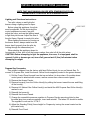
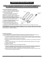
Chef’s Line® Gas Griddles
Installation & Operating Instructions
PART #359341
(See page 5 for Operating Instructions.)
FOR YOUR SAFETY:
DO NOT STORE OR USE GASOLINE OR OTHER FLAMMABLE VAPORS AND LIQUIDS
IN THE VICINITY OF THIS OR ANY OTHER APPLIANCE.
Models #CLAGGH, CLAGGHT and CLAGGHTS SERIES
$1@-5:@45?9-:A-82;>2A@A>1>121>1:/1
;:@-/@@45?2-/@;>E@412-/@;>E>1<>1?1:@-@5B1;>-8;/-8?1>B5/1/;9<-:E@;<1>2;>99-5:@1:-:/1-:0>1<-5>?
Eagle Foodservice Equipment, Eagle MHC, SpecFAB, and Retail Display are divisions of Eagle Group. ©2012 by the Eagle Group
• 100 Industrial Boulevard, Clayton, Delaware 19938-9905 U.S.A. • www.eaglegrp.com
• Phone: 302/653-3000 • (Foodservice) 800/441-8440 • (MHC/Retail) 800/637-5100
• Fax: 302/653-2065
'&!
INSPECT CONTENTS IMMEDIATELY AND FILE CLAIM WITH DELIVERING CARRIER FOR ANY DAMAGE.
%(+!'$!* " &$%
YOU ARE RESPONSIBLE FOR DAMAGE TO YOUR UNIT IF RETURNED IMPROPERLY PACKED.
NOTE: INTENDED FOR OTHER THAN HOUSEHOLD USE. THIS COMMERCIAL
APPLIANCE MUST BE INSTALLED WITHIN SURROUNDINGS AND VENTILATION
REQUIREMENTS AS DICTATED BY NATIONAL AND/OR LOCAL CODE.

%&&! %&$'&! %
"!$& &
BEFORE PLACING THIS APPLIANCE IN OPERATION, CONTACT YOUR LOCAL GAS SUPPLIER
AS TO WHAT INSTRUCTIONS ARE TO BE FOLLOWED IF YOU SMELL GAS. THE
INSTRUCTIONS OBTAINED SHOULD THEN BE POSTED IN A PROMINENT LOCATION.
This griddle is designed for installation as an independent HEAVY DUTY APPLIANCE and is not
intended for residential use.
(See page 5 for Operating Instructions.)
$ %&$'&! %
Appliances for installation on non-combustible countertops only. 5:59A9/81->-:/12>;9
/;[email protected]/;:?@>A/@5;:5?5:/41?2>;9@41?501?5:/41?2>;9@41.-/7-:05:/41?
2>;9@;<;2@413>50081
The appliance area must be free and clear of all combustible items.
The unit must be leveled before placing it in operation. To level the unit on an uneven surface to
prevent rocking, adjustable feet have been provided.
When using gas griddle, keep the appliance area free from obstructions that can block the flow
of combustible gases.
IMPROPER INSTALLATION, ADJUSTMENT, ALTERATION, SERVICE OR MAINTENANCE CAN
CAUSE PROPERTY DAMAGE, INJURY OR DEATH. READ THE INSTALLATION, OPERATING
AND MAINTENANCE INSTRUCTIONS THOROUGHLY BEFORE INSTALLING OR SERVICING
THIS EQUIPMENT.
WARNING
FOR YOUR SAFETY
IF YOU SMELL GAS:
1. DO NOT TOUCH ELECTRIC SWITCHES
2. EXTINGUISH ANY OPEN FLAME
3. IMMEDIATELY CALL YOUR GAS COMPANY
WARNING

%! &! %
Installation Personnel: Check all connections and fittings on valves and tubing supplied as a part
of this unit to make sure they did not come loose during shipment. A manual shutoff gas valve
should be provided upstream within 6 feet of the appliance for shutting the gas off during servicing.
A ground joint union should be provided between the house plumbing and the gas inlet to the
appliance. A gas pressure regulator has been provided as a part of this appliance. It is factory pre-
set for natural gas and is field adjustable for liquid propane gas. +*!&%,(-/')!
!%#*'())+(All plumbing should be clean and free of burrs and metal chips. All pipe connections
should be made using a pipe joint compound resistant to the action of LP gases. A drip TEE must be
used to collect any moisture or dirt in the gas. Upon completing the installation of this appliance, all
the gas connections must be checked for gas leaks. Use a solution of liquid dishwashing soap and
water to check for leaks. On models with safety pilot, check the lighter tube for correct position.
This installation must conform with local codes, or in the absence of local codes with the National
Fuel Gas Code ANSI Z223.1/NFPA 54, or the National Gas and Propane Installation code
CSA-B149.1 as applicable.
The appliance must be isolated from the gas supply piping system by closing it’s individual
manual shutoff gas valve during any pressure testing of the gas supply piping system at test
pressures equal to or more than 1/2˝ psig (3.45 kPa).
Provisions for proper air supply must be taken into account when installing the unit. Care should
be taken so as not to obstruct the area in front and in rear of the unit. DO NOT PLACE BACK OF
THE UNIT CLOSER THAN 10 INCHES TO A WALL OR OTHER SURFACES.
The appliance shall be located with respect to other equipment so it will have adequate
clearances for servicing and proper operation.
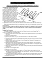
This unit is supplied with four (4) adjustable feet, which must be installed prior to operation. Four
(4) threaded openings are provided on bottom of the unit to accept the threaded portion of the feet.
Screw in the feet and tighten them securely. During operation, check the feet every sixty (60) days
to assure that they are tight. Failure to use the feet will void warranty and could cause unsafe
conditions.
!&<<85-:/19A?@.15:?@-8810A:01>-B1:@58-@5;:4;;0
%& '%&&$'&!$ $%" %%
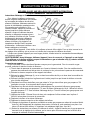
The following items are not installed at the factory and are shipped loose in the grease pan:
[email protected]11@ This unit is provided with four (4) adjustable feet, which must be installed '(!&(to
operation. Four (4) threaded openings are provided on bottom of the unit to accept the threaded
portion of the feet. Screw in the feet and tighten them securely. During operation, check the feet
every sixty (60) days to assure they are tight.
-?">1??A>1$13A8-@;> The provided regulator is convertible for either Propane or Natural Gas.
Insure the regulator is set for gas being used. Install with appropriate sealing compound.
>1-?1"-:-:0%8501? The grease pan and slides must be installed &( use. Left and right
slides are provided. These are installed on the underside of the unit with the six-(6) 10-32 screws
provided. Slide grease pan into position after installing slides.
( ' &
Level unit by adjusting the four (4) feet, which have an adjustment of one inch for lineup with other
Eagle Countertop lines.
%&&! %&$'&! %/;:@5:A10

534@5:3-:0%4A@0;C::?@>A/@5;:?
To light pilot, push in the red reset
button on the safety pilot valve body
and light the pilot. Hold reset button in
for approximately 30 seconds, then
release. If the pilot goes out, repeat the
above procedure until the pilot stays lit.
When the pilot stays lit, a valve disc will
open to permit gas flow to the burner.
Turn thermostatic controls to full ON
position to light burners, then set to
desired temperature. Check the main
burner for proper lighting and burning using
the observation port provided.
Before using this appliance, the pilot must be checked
for adjustment. Do this by turning the pilot adjustment screw located on the safety pilot valve body.
When shutting the appliance down for long periods of time, shut off all thermostatic controls; then
shut off the pilot.
%(**#&*!$*%"! ** &&"!$* %,(!)%'+!&&) ""%&$
&!"%*%(+($(%)%+**+($%"")$-!*!,+""#!$+*)%(**#&*!$*%
("! *
' &%)&'&!&%&+"!& &$!%&&! &$!%
%&&! %&$'&! %/;:@5:A10
">;<-:1-?;:B1>?5;:
This griddle is shipped from the factory with fixed Orifice Hoods for use on Natural Gas. To
convert to Propane Gas, follow these steps:
1) Remove screws. Remove control knobs. Pull the control panel forward from top and allow to
drop down.
2) Remove the Access Panels.
3) Remove lighter tubes one (1) on 24" model and two (2) on 36" and 48" models.
4) Remove the main burner(s) by sliding the burner toward the rear until the front part of burner
clears the hood.
5) Replace Natural Gas Burner Orifices #41 with Propane Gas Orifice(s) #52 marked in red
(located in the grease drawer).
6) Replace the lighter tube Orifice fitting(s) with Propane Orifice fitting(s). Use #73 Propane
Gas Orifice for 19" long lighter tubes. Use #77 Propane Gas Orifice for 9" long lighter tubes.
All Propane Gas Orifices will be marked with red.
7) Safety Pilot: Remove bottom nut, and replace existing orifice with part #305109 included with
conversion kit.
8) Reinstall burner and lighter tubes.
9) Reinstall the Access Panels.
10) Change the convertible pressure regulator to Propane Gas by removing slotted or hex
threaded plug from pressure regulator, invert and reinstall. The letters LP should be visible.
The regulator is now set for 10˝ W.C.
11) Follow instructions to light the safety pilot – adjust the flame for Propane Gas by turning the
pilot adjustment screw located next to the red button on the auto safety pilot valve body.
12) Reinstall Front Panel.

' &%&&( '((%)&%& "!&%!$
&$!%&&! &$!%)&%& "!&%
534@5:3-:0%4A@0;C::?@>A/@5;:?
Turn pilot valves on and light pilot
burners using a lighting wand or taper.
Before using this appliance, the pilots
must be adjusted. Do this by turning the
control adjustment screw in one pilot,
adjust the valve, and use the lighting wand
to light that pilot burner. Adjust the size of
the pilot flame. Repeat for each pilot valve.
When lighting the burners by turning on
the burner knobs, always make sure the
burner has lit properly from the pilot by
looking through the observation port.
When shutting the appliance down for
long periods of time, shut off all the burners valves; then shut off all the pilot valves.
%(**#&*!$*%"! ** &&"!$* %,(!)%'+!&&) ""
%&$&!"%*%(+($()%%+**+($%"")$-!*!,+""#!$+*)%(
**#&*!$*%("! *
">;<-:1-?;:B1>?5;:
This griddle is shipped from the factory with fixed Orifice Hoods for use on Natural Gas. To
convert to Propane Gas, install the burner Orifice Hoods supplied (located in the grease drawer).
1) Pull the Control Panel forward from the top and allow it to drop down. On models where
control panel is attached with screws, remove screws then remove control panel.
2) Remove the Access Panels.
3) Remove burner(s) from the Orifice Hood(s) by sliding the burner toward the rear and lifting
off the hood(s).
4) Remove #41 Natural Gas Orifice Hood(s) and install the #52 Propane Gas Orifice Hood(s)
marked in red.
5) Reinstall the burner(s).
6) Reinstall the Access Panels.
7) Change the convertible pressure regulator to Propane Gas by removing slotted or hex
threaded plug from pressure regulator, invert and reinstall. The letters LP should be visible.
The regulator is now set for 10˝ W.C.
8) Adjust the Standing Pilot(s) flame height for Propane by turning the screw located on the
pilot valve body.
9) Reinstall Front Panel.
%&&! %&$'&! %/;:@5:A10

&!%%! &$& %'$
Clean the griddle surface thoroughly. After the griddle has been thoroughly cleaned, it should be seasoned
to prevent food from sticking. Before using and after each thorough scouring, season the griddle-heating
surface in the following manner:
1) Bring griddle up to a cooking temperature of about 350 degrees F.
2) Using a clean cloth, not a spatula, spread a thin film of cooking oil/fat over the griddle cooking
surface. This film should remain on the hot griddle surface for half-hour.
3) Remove the excess oil/fat and wipe clean. (CAUTION: GRIDDLE SURFACE WILL BE HOT).
4) Apply another film of cooking oil/fat over the hot cooking area for another half-hour and again
remove the excess oil/fat and wipe clean. The griddle surface will be ready for use.
Even with careful seasonings, food may, to some extent, stick to the griddle cooking surface until the
griddle plate is "broken in".
During idle periods, to save on operating cost, lower the temperature setting of the thermostats to about
250 degrees F. It is not necessary to maintain a cooking temperature during idle periods, as the griddle can
quickly be reheated to desired temperature.
&%"" %#'""!$ &'$%
This appliance is equipped with Orifices sized for operation with Natural Gas. %(%$,()!%$*%
(%&$))!$)*(+*!%$&"*%$* &&"!$(!!)$))(.%((%&$%$,()!%$(
&(%,!!$()(-(
$$
1) After each use, scrape the griddle with a scraper or a flexible spatula to remove excess fat and food. A
grease drawer is provided for the scrapings. If there is an accumulation of burned on fat and food, the griddle
should be thoroughly scoured and re-seasoned as outlined above. Use pumice or griddle stone while the
griddle is warm. Do not use steel wool because of the danger of steel slivers getting into the food.
2) Daily use a clean cloth and a good non-abrasive cleaner to clean the stainless steel body of the griddle.
Wipe the polished front with a soft cloth.
3) At least once a day, remove the grease drawer and wash in the way as an ordinary cooking utensil. If
the grease drawer is permitted to fill too high, the excess grease will run out of the overflow hole at the front
of the drawer. The drawer is removed by pulling forward.
'%'&! ) )&!&$%
!"$& %&$'&! %
&$!'%!!& $&
&>;A.81 -A?1 $1910E
Griddle will not heat A) Burner not on Check pilot light operation and turn burner on
B) Gas supply shut off Turn off burner valves and pilot light valves,
turn gas on and follow lighting procedure
Griddle surface too hot A) Frying unevenly Space out food uniformly on
griddle surface
Food sticking A) Grease or food particles See “Griddle Care,” page 5
accumulating on surface
B) Not seasoned See “Griddle Care,” page 5
Liquid runs to one side A) Not level See “Leveling Unit,” page 2
!&If service is required, call local service company from directory provided or call factory for referral to agency in your region.

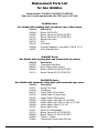
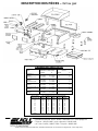
Replacement Parts List
for Gas Griddles
;018<>125D1?&&%
"->@?->12;>A:5@?9-:A2-/@A>10-2@1><>5;>@;
CLAGGH Series
Gas Griddle with standing pilot and manual valves (Core items)
"->@ ; 1?/>5<@5;:
355448 . . . . Burner 30,000 BTU
360983 . . . . Burner Orifice #41 NG 30,000 BTU
312131 . . . . Burner Orifice #52 LP 30,000 BTU
332778 . . . . Manual Gas Valve
366794 . . . . Pilot
333142 . . . . Pilot Valve
324949 . . . . Pressure Regulator, Convertible 4˝ NG & 10˝ LP
349397 . . . . Knob, Manual Valve
CLAGGHT Series
Gas Griddle with standing pilot and thermostatic gas valves
"->@ ; 1?/>5<@5;:
324793 . . . . Thermostat Gas Valve
358464 . . . . Knob, Thermostatic Control
360983 . . . . Burner Orifice #41 NG 30,000 BTU
312131 . . . . Burner Orifice #52 LP 30,000 BTU
CLAGGHTS Series
Gas Griddle with automatic safety pilot and thermostatic gas valves
"->@ ; 1?/>5<@5;:
374737 . . . . Safety Pilot Valve
374738 . . . . Pilot Burner
305277 . . . . Lighter Tube 19˝ Left Hand
305278 . . . . Lighter Tube 19˝ Right Hand
305276 . . . . Lighter Tube 9˝ Right Hand
305296 . . . . Orifice Lighter Tube #63 (19˝ tube NG)
305295 . . . . Orifice Lighter Tube #73 (19˝ tube LP, 9˝ NG)
305294 . . . . Orifice Lighter Tube #77 (9˝ LP)
302097 . . . . Elbow Lighter Tube
311937 . . . . Elbow 90˚ 3/8 Bulkhead
312131 . . . . Burner Orifice #52 LP 30,000 BTU
360983 . . . . Burner Orifice #41 NG 30,000 BTU
309879 . . . . Thermo - Couple
374805 . . . . Thermostatic Control with Pilot Key

Eagle Foodservice Equipment, Eagle MHC, SpecFAB
®
, and Retail Display are divisions of Eagle Group. ©2012 by the Eagle Group
• 100 Industrial Boulevard, Clayton, Delaware 19938-9905 U.S.A. • www.eaglegrp.com
• Phone: 302/653-3000 • (Foodservice) 800/441-8440 • (MHC/Retail) 800/637-5100
• Fax: 302/653-2065
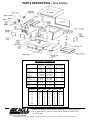
"$&%%$"&! NGas Griddle
ORIFICE DRILL SIZE / EAGLE PART # INCHES IN
SERIES NATURAL GAS LIQUID PROPANE WATER COLUMN
(NG) (LP) NG LP
CLAGGHTS-24
- Burners 41 / 360983 52 / 312131 4˝ 10˝
- Runner Tube 9˝ 73 / 305295 77 / 305294 4˝ 10˝
CLAGGHTS-36
- Burners 41 / 360983 52 / 312131 4˝ 10˝
- Runner Tube 19˝ 60 / 360985 67 / 360986 4˝ 10˝
CLAGGHTS-48
- Burners 41 / 360983 52 / 312131 4˝ 10˝
- Runner Tube 19˝ (2) 60 / 360985 67 / 360986 4˝ 10˝
CLAGGHT
- Burners 41 / 360983 52 / 312131 4˝ 10˝
CLAGGH
- Burners 41 / 360983 52 / 312131 4˝ 10˝
GAS ORIFICE INFORMATION
ORIFICE SIZE ORIFICE SIZE REQUIRED AT OTHER ELEVATIONS
AT SEA LEVEL 2000 ft 3000 ft 4000 ft 5000 ft 9000 ft
32 33 34 35 35 38
39 40 41 41 42 44
41 42 42 42 43 45
50 51 51 51 51 53
51 51 52 52 52 53
52 52 53 53 53 54
60 64 64 65 65 67
67 68 68 68 69 70
73 73 77 77 78 78
77 77 77 77 78 78
1.55mm 54 54 54 54 55

EG10058 Dernière révision : 02/12
%&$'&! %R %&&!
Gril au gaz Chef’s Line®
Instructions d’installation et d’utilisation
Nº PIÈCE 359341
(Voir la page 5 pour connaître les instructions d’utilisation.)
Modèles de la série CLAGGH, CLAGGHT et CLAGGHTS
;:?1>B1F81<>I?1:@9-:A18<;A>B;A?E>I2I>1>A8@I>51A>191:@
"
;A>1221/@A1>8R1:@>1@51:018R-<<->158;A81>I<->1>/;99A:5=A1F-B1/
81>1<>I?1:@-:@0A2-.>5/-:@;A-B1/A:11:@>1<>5?101?1>B5/18;/-81
Eagle Foodservice Equipment, Eagle MHC, SpecFAB
®
et Retail Display sont des divisions du Eagle Group. ©2012, Eagle Group
• 100 Industrial Boulevard, Clayton, Delaware 19938-9905 U.S.A. • www.eaglegrp.com
• Téléphone : (302) 653-3000 • (service alimentaire) 1 800 441-8440
• (SC / Vente au détail) 1 800 637-5100 • Télécopieur : 302/653-2065
($&%% &
INSPECTEZ IMMÉDIATEMENT LE CONTENU DE L’EMBALLAGE ET ENVOYEZ UNE
DEMANDE D’INDEMNISATION AU SERVICE DE TRANSPORT EN CAS DE DOMMAGE.
! %$(,!P&&&!'&&G$R
VOUS SEREZ RESPONSABLE DES DOMMAGES À L’APPAREIL SI
CELUI-CI EST MAL EMBALLÉ LORS DE SON RETOUR.
POUR VOTRE SÉCURITÉ :
N’UTILISEZ PAS ET NE STOCKEZ PAS DE GAZOLINE OU TOUT AUTRE LIQUIDE
INFLAMMABLE OU DÉGAGEANT DES VAPEURS INFLAMMABLES PRÈS DE
CET APPAREIL OU DE TOUT AUTRE APPAREIL.
NOTE: VOULE POUR AUTREMENT QUE L’USAGE DOMESTIQUE. CET APPAREIL
COMMERCIAL DOIT ETRE INSTALLE DANS LES CONDITIONS D’ENVIRONS ET
VENTILATION COMME DICTE PAR ET/OU NATIONAL LE CODE LOCAL.
Page is loading ...
Page is loading ...
Page is loading ...
Page is loading ...
Page is loading ...
Page is loading ...
Page is loading ...
-
 1
1
-
 2
2
-
 3
3
-
 4
4
-
 5
5
-
 6
6
-
 7
7
-
 8
8
-
 9
9
-
 10
10
-
 11
11
-
 12
12
-
 13
13
-
 14
14
-
 15
15
-
 16
16


Eagle CLAGGH Series Installation & Operating Instructions Manual
- Category
- Electric griddles
- Type
- Installation & Operating Instructions Manual
- This manual is also suitable for
Ask a question and I''ll find the answer in the document
Finding information in a document is now easier with AI
in other languages
- français: Eagle CLAGGH Series
Related papers
Other documents
-
 Prime-Line U 9905 Operating instructions
-
Eagle Group EGH-36 Operating instructions
-
 Connerton Co CEG SERIES User manual
-
Vulcan VCRG36-T Owner's manual
-
-
Eagle Group CLAGGHT-36-NG Datasheet
-
-
Vollrath Griddle, Gas, Heavy-Duty, Cayenne® User manual
-
-
Wells Manufacturing HDTG-4830G Operating instructions

