- 17 -
& Time (hh:mm:ss)
Sets the system time.
& IDE Channel 0, 1 Master
IDE Channel 0, 1 Master
Congure your SATA devices by using one of the three methods below:
• None If no SATA devices are used, set this item to None so the system will skip the
detection of the device during the POST for faster system startup.
• Auto Lets the BIOS automatically detect SATA devices during the POST. (Default)
• Manual Allows you to manually enter the specications of the hard drive when the hard
drive access mode is set to CHS.
Access Mode Sets the hard drive access mode. Options are: Auto (default), CHS, LBA, Large.
& Halt On
Allows you to determine whether the system will stop for an error during the POST.
Options are: "All Errors," "No Errors," "All, But Keyboard". (Default)
& Memory
These elds are read-only and are determined by the BIOS POST.
2-4 Advanced BIOS Features
& Hard Disk Boot Priority
Species the sequence of loading the operating system from the installed hard drives. Use the up or
down arrow key to select a hard drive, then press the plus key <+> (or <PageUp>) or the minus key <->
(or <PageDown>) to move it up or down on the list. Press <Esc> to exit this menu when nished.
& Quick Boot
Enables or disables the quick boot function to speed up the system boot-up process to shorten the waiting
time for entering the operating system and to deliver greater efciency for daily use. (Default: Disabled)
& First/Second/Third Boot Device
Species the boot order from the available devices. Use the up or down arrow key to select a device and
press <Enter> to accept. Options are: LS120, Hard Disk, CDROM, ZIP, USB-FDD, USB-ZIP, USB-CDROM,
USB-HDD, Legacy LAN, Disabled.
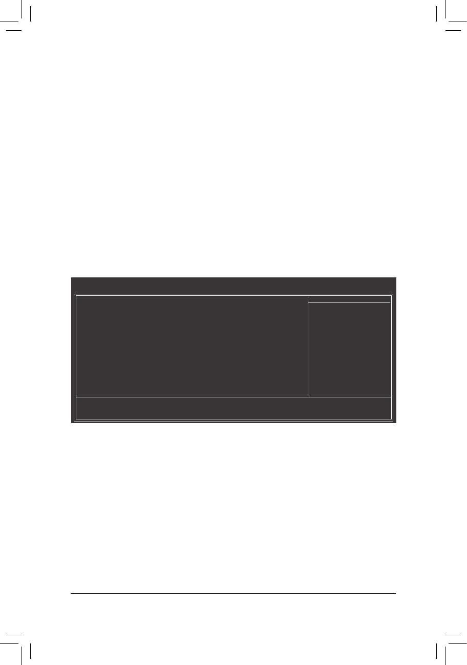
CMOS Setup Utility-Copyright (C) 1984-2010 Award Software
Advanced BIOS Features
Hard Disk Boot Priority [Press Enter]
Quick Boot [Disabled]
First Boot Device [Hard Disk]
Second Boot Device [CDROM]
Third Boot Device [USB-FDD]
Password Check [Setup]
HDD S.M.A.R.T. Capability [Enabled]
CPU Multi-Threading
[Enabled]
Limit CPUID Max. to 3
[Disabled]
Delay For HDD (Secs) [0]
Backup BIOS Image to HDD [Disabled]
Init Display First [PCI]
On-Chip Frame Buffer Size [8MB+1 for GTT]
: Move Enter: Select +/-/PU/PD: Value F10: Save ESC: Exit F1: General Help
F5: Previous Values F6: Fail-Safe Defaults F7: Optimized Defaults
Item Help
Menu Level


