
D6138
4
13
English (original instructions)

2

F
D
C
G
A
E
I
E
A
FIG. 1
. 1

M
N
O
I
E
E
E
O
R
M
FIG. 3A
FIG. 4
. 3A
. 4

10-15˚
E
E
FIG. 5
FIG. 6
FIG. 7
. 5
. 6
. 7

E N G L I S H (original instructions)
4
POLISHERS
D6138
Congratulations!
You have chosen a Black&Decker power tool. Years of experience, thorough product development and
innovation make Black&Decker one of the most reliable partners for professional power tool users.
Technical data
D6138
Rated voltage V
AC
220-240
Rated frequency Hz 50/60
Power input W 1100
No-load speed r/min 0-600/0-3500
Pop-off brushes NO
Spindle M14
Side handle Auxiliary
Weight kg 2.85
Definitions: Safety Guidelines
The definitions below describe the level of severity
for each signal word. Please read the manual and
pay attention to these symbols.
DANGER: Indicates an imminently
hazardous situation which, if not avoided,
will result in death or serious injury.
WARNING: Indicates a potentially
hazardous situation which, if not
avoided, could result in death or
serious injury.
CAUTION: Indicates a potentially
hazardous situation which, if not
avoided, may result in minor or
moderate injury.
CAUTION: Used without the safety alert
symbol indicates a potentially hazardous
situation which, if not avoided, may
result in property damage.
electric shock.
Denotes
Denotes
risk of
risk of
fire.
WARNING: To reduce the risk of injury,
read the instruction manual.
General Power Tool Safety Warnings
WARNING! Read all safety warnings
and all instructions Failure to follow
the warnings and instructions may
result in electric shock, fire and/or
serious injury.
SAVE ALL WARNINGS AND INSTRUCTIONS
FOR FUTURE REFERENCE.
The term “power tool” in the warnings refers to your
mains-operated (corded) power tool or battery-
operated (cordless) power tool.
1) WORK AREA SAFETY
a) Keep work area clean and well lit.
Cluttered or dark areas invite acciden
ts.
b) Do not operate power tools in explosive
atmospheres, such as in the presence of
flammable liquids, gases or dust. Power
tools create sparks which may ignite the dust
or fumes.
c) Keep children and bystanders away while
operating a power tool. Distractions can
cause you to lose control.
2) ELECTRICAL SAFETY
a) Power tool plugs must match the outlet.
Never modify the plug in any way. Do
not use any
adapter plugs with earthed

E N G L I S H
5
(grounded) power tools. Unmodified plugs
and matching outlets will reduce risk of
electric shock.
b) Avoid body contact with earthed or
grounded surfaces such as pipes,
radiators, ranges and refrigerators. There
is an increased risk of electric shock if your
body is earthed or grounded.
c) Do not expose power tools to rain or wet
conditions. Water entering a power tool will
increase the risk of electric shock.
d) Do not abuse the cord. Never use the
cord for carrying, pulling or unplugging
the power tool. Keep cord away from
heat, oil, sharp edges or moving parts.
Damaged or entangled cords increase the
risk of electric shock.
e) When operating a power tool outdoors,
use an extension cord suitable for outdoor
use. Use of a cord suitable for outdoor use
reduces the risk of electric shock.
f) If operating a power tool in a damp
location is unavoidable, use a residual
current device (RCD) protected supply.
Use of an RCD reduces the risk of electri
c
shock.
3) PERSONAL SAFETY
a) Stay alert, watch what you are doing and
use common sense when operating a
power tool. Do not use a power tool while
you are tired or under the influence of
drugs, alcohol or medication. A moment of
inattention while operating power tools may
result in serious personal injury.
b) Use personal protective equipment.
Always wear eye protection. Protective
equipment such as dust mask, non-skid
safety shoes, hard hat, or hearing protection
used for appropriate conditions will reduce
personal injuries.
c) Prevent unintentional starting. Ensure
the switch is in the off-position before
connecting to power source and/or
battery pack, picking up or carrying the
tool. Carrying power tools with your finger
on the switch or energising power tools that
have the switch on invites accidents.
d) Remove any adjusting key or wrench
before turning the power tool on. A
wrench or a key left attached to a rotating
part of the power tool may
result in personal
injury.
e) Do not overreach. Keep proper
footing and balance at all times. This
enables better control of the power tool in
unexpected situations.
f) Dress properly. Do not wear loose
clothing or jewellery. Keep your hair,
clothing and gloves away from moving
parts. Loose clothes, jewellery or long hair
can be caught in moving parts.
g) If devices are provided for the connection
of dust extraction and collection facilities,
ensure these are connected and properly
used. Use of dust collection can reduce
dust-related hazards.
4) POWER TOOL USE AND CARE
a) Do not force the power tool. Use the
correct power tool for your application.
The correct power tool will do the job
better and safer at the rate for which it
was designed.
b) Do not use the power tool if the switch
does not turn it on and off. Any power
tool that cannot be controlled with the switch
is dangerous and must be repaired.
c) Disconnect the plug from the power
source and/or the battery pack from
the power tool before making any
adjustments, changing accessories, or
storing power tools. Such preventive safety
measures reduce the risk of starting the
power tool accidentally.
d) Store idle power tools out of the reach
of children and do not allow persons
unfamiliar with the power tool or these
instructions to operate the power tool.
Power tools are dangerous in the hands of
untrained users.
e) Maintain power tools. Check for
misalignment or binding of moving parts,
breakage of parts and any other condition
that may affect the power tools operation.
If damaged, have the power tool repaired
before use. Many accidents are caused by
poorly maintained power tools.
f) Keep cutting tools sharp and clean.
Properly maintained cutting tools with sharp
cutting edges are less likely to bind and are
easier to control.
g) Use the power tool, accessories and
tool bits etc., in accordance with these
instructions taking into
account the
working conditions and the work to
be performed. Use of the power tool for
operations different from those intended
could result in a hazardous situation.
5) SERVICE
a) Have your power tool serviced by a
qualified repair person using only identical
replacement parts. This will ensure that the
safety of the power tool is maintained.
(original instructions)

E NGLIS H (original instructions)
6
b) When servicing a tool, use only identical
replacement parts. Follow instructions in
the Maintenance section of this manual.
Use of unauthorized parts or failure to follow
maintenance instructions may create a risk of
electric shock or injury.
Safety instructions for All operations
a) This power tool is intended to function
as a polisher and sander. Read all safety
warnings, instructions, illustrations and
specifications provided with this power
tool. Failure to follow all instructions listed
below may result in electric shock, fire and/or
serious injury.
b) Operations such as grinding, wire
brushing or cutting-off are not
recommended to be performed with this
power tool. Operations for which the power
tool was not designed may create a hazard
and cause personal injury.
c) Do not use accessories which are not
specifically designed and recommended
by the tool manufacturer. Just because the
accessory can be attached to your power
tool, it does not assure safe operation.
d) The rated speed of the accessory
must
be at least equal to the maximum speed
marked on the power tool. Accessories
running faster than their rated speed can
break and fly apart.
e) The outside diameter and the thickness
of your accessory must be within the
capacity rating of your power tool.
Incorrectly sized accessories cannot be
adequately guarded or controlled.
f) The arbor size of wheels, flanges,
backing pads or any other accessory
must properly fit the spindle of the power
tool. Accessories with arbor holes that do
not match the mounting hardware of the
power tool will run out of balance, vibrate
excessively and may cause loss of control.
g) Do not use a damaged accessory.
Before each use inspect the accessory
such as abrasive wheels for chips and
cracks, backing pad for cracks, tear or
excess wear, wire brush for loose or
cracked wires. If power tool or accessory
is dropped, inspect for damage or
install an undamaged accessory. After
inspecting and installing an accessory,
position yourself and bystanders away
from
the plane of the rotating accessory
and run the power tool at maximum
no-load speed for one minute.Damaged
accessories will normally break apart during
this test time.
h) Wear personal protective equipment.
Depending on application, use face
shield, safety goggles or safety glasses.
As appropriate, wear dust mask, hearing
protectors, gloves and workshop apron
capable of stopping small abrasive or
workpiece fragments. The eye protection
must be capable of stopping flying debris
generated by various operations. The
dust mask or respirator must be capable
of filtrating particles generated by your
operation. Prolonged exposure to high
intensity noise may cause hearing loss.
i) Keep bystanders a safe distance away
from work area. Anyone entering the
work area must wear personal protective
equipment. Fragments of workpiece or of a
broken accessory may fly away and cause
injury beyond immediate area of operation.
j) Hold power tool by insulated gripping
surfaces only, when performing an
operation where the cutting accessory
may contact hidden wiring or its own
cord. Cutting accessor
y contacting a “live”
wire may make exposed metal parts of the
power tool “live” and shock the operator.
k) Position the cord clear of the spinning
accessory. If you lose control, the cord may
be cut or snagged and your hand or arm
may be pulled into the spinning accessory.
l) Never lay the power tool down until the
accessory has come to a complete stop.
The spinning accessory may grab the surface
and pull the power tool out of your control.
m) Do not run the power tool while carrying
it at your side. Accidental contact with the
spinning accessory could snag your clothing,
pulling the accessory into your body.
n) Regularly clean the power tool’s air vents.
The motor’s fan will draw the dust inside
the housing and excessive accumulation
of powdered metal may cause electrical
hazards.
o) Do not operate the power
tool near
flammable materials. Sparks could ignite
these materials.
p) Do not use accessories that require
liquid coolants. Using water or other liquid
coolants may result in electrocution or shock.

E N G L I S H
7
Further Safety instructions for All
operations
KICKBACK AND RELATED WARNINGS
Kickback is a sudden reaction to a pinched or
snagged rotating wheel, backing pad, brush or
any other accessory. Pinching or snagging causes
rapid stalling of the rotating accessory which in turn
causes the uncontrolled power tool to be forced in
the direction opposite of the accessory’s rotation at
the point of the binding.
For example, if an abrasive wheel is snagged or
pinched by the workpiece, the edge of the wheel
that is entering into the pinch point can dig into the
surface of the material causing the wheel to climb
out or kick out. The wheel may either jump toward
or away from the operator, depending on direction
of the wheel’s movement at the point of pinching.
Abrasive wheels may also break under these
conditions.
Kickback is the result of tool misuse and/or incorrect
operating procedures or conditions and can be
avoided by taking proper precautions as given
below:
a) Maintain a firm grip on the power tool
and position your body and arm to allow
you to resist kickback forces. Always use
auxiliary handle, if provided, for maximum
control over kickback or torque reaction
during start up. The operator can control
torque reaction or kickback forces, if proper
precautions are taken.
b) Never place your hand near the rotating
accessory. Accessory may kickback over
your hand.
c) Do not position your body in the area
where power tool will move if kickback
occurs. Kickback will propel the tool in
direction opposite to the wheel’s movement
at the point of snagging.
d) Use special care when working corners,
sharp edges, etc. Avoid bouncing and
snagging the accessory. Corners, sharp
edges or bouncing have a tendency to snag
the rotating accessory and
cause loss of
control or kickback.
e) Do not attach a saw chain woodcarving
blade or toothed saw blade. Such blades
create frequent kickback and loss of control.
Safety Warnings Specific for
Polishing operations
a) Do not allow any loose portion of the
polishing bonnet or its attachment strings
to spin freely. Tuck away or trim any loose
attachment strings. Loose and spinning
attachment strings can entangle your fingers
or snag on the workpiece.
b) When adding lubricating oil and changing
accessories please follow this manual
instruction.
c) The handle must keep dry clean and
without oil.
Safety Warnings Specific for Sanding
operations
a) Do not use excessively oversized sanding
disc paper. Follow manufacturer’s
recommendations, when selecting
sanding paper. Larger sanding paper
extending beyond the sanding pad presents
a laceration hazard and may cause snagging,
tearing of the disc or kickback.
b) When adding lubricating oil and changing
accessories please follow this manual
instruction.
c) The handle must keep dry clean and
without oil.
Additional Specific Safety
instructions for Polishers
• Always use eye protection. All users and
bystanders must wear eye protection that
conforms to ANSI Z87.1.
• Clean out your tool often, especially
after heavy use. Dust and grit containing
metal particles often accumulate on interior
surfaces and could create an electric shock
hazard.
• Do not operate this tool for long periods
of time. Vibration caused by the operating
action of this tool may cause permanent
injury to fingers, hands and arms. Use gloves
to provide extra cushion, take frequent rest
periods and limit daily time of use.
• Air vents often cover moving parts and
should be avoided. Loose clothes, jewelry
or long hair can be caught in moving parts.
WARNING: ALWAYS use safety
glasses. Everyday eyeglasses are
NOT safety glasses. Also use face or
dust mask if cutting operation is dusty.
ALWAYS WEAR CERTIFIED SAFETY
(original instructions)

E N G L I S H
8
EQUIPMENT.
WARNING: Always wear proper
personal hearing protection that
conforms to ANSI S12.6 (S3.19)
during use. Under some conditions and
duration of use, noise from this product
may contribute to hearing loss.
WARNING: Some dust created by
power sanding, sawing, grinding,
drilling, and other construction
activities contains chemicals known to
cause cancer, birth defects, or other
reproductive harm. Some examples of
these chemicals are:
• lead from lead-base d paints,
• crystalline silica from bricks and cement and
other masonry products, and
• arsenicand chromiu m from chemically-
treated lumber.
Your risk from these exposures varies, depending
on how often you do this type of work. To reduce
your exposure to these chemicals: work in a well
ventilated area, and work with approved safety
equipment, such as those dust masks that are
specially designed to filter out microscopic particles.
• Avoid prolonged contact with dust from
power sanding, sawing, grinding, drilling
and other construction activities. Wear
protective clothing and wash exposed
areas with soap and water. Allowing dust
to get into your mouth,
eyes, or lay on the
skin may promote absorption of
harmful
chemicals.
WARNING:Use of this tool can
generate and/or disperse dust, which
may cause serious and permanent
respiratory or other injury. Always
use NIOSH/OSHA approved respiratory
protectionappropriate for the dust
exposure. Direct particles away from
face and body.
CAUTION: Use extra care when
working into a corner because a
sudden, sharp movement of the polisher
may be experienced when the wheel or
other accessory contacts a secondary
surface or a surface edge.
• yoThe label on ur tool may include the
following symbols. The symbols and their
definitionsareas follows:
Save These Instructions
Motor
Your Black&Decker tool is powered by a DEWALT-
built motor. Be sure your power supply agrees with
the nameplate marking. Voltage decrease of
more
than 10% will cause loss of power and overheating.
Black&Decker tools are factory tested; if this tool
does not
operate, check power supply.
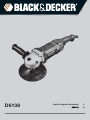
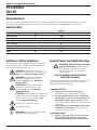
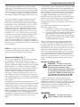
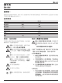
Components (fig. 1)
WARNING: Never modify the power
tool or any part of it. Damage or personal
injury could result.
A. Speed control wheel
C. Variable speed trigger switch
D. Brush inspection cap
E. Spindle lock button
F. Auxiliary handle
G. Trigger locking button
I. Spindle
M. Clamp washer
O. Backing pad
N. Polishing pad
R. Sanding disc
INTENDED USE
The D6138 heavy-duty polishers are designed
for professional use at various work sites (i.e.,
construction sites). Do not use under humid
co
nditions or in presence of flammable liquids or
gases.
The D6138 heavy-duty polishers are professional
power tools. Do not let children come into contact
with the tool. Supervision is required when
inexperienced operators use this tool.
Auxiliary handle (fig. 1)
An auxiliary handle (F) is furnished with your tool
and can be installed on either side of the gear case.
This handle should be used at all times to maintain
complete control of the tool.
Variable Speed Trigger Switch (fig. 1)
(original instructions)

E N G L I S H
9
These tools are equipped with a variable speed
trigger switch that permits speed control from 0 to
3500 RPM. To turn the tool on, squeeze the trigger
switch (C) shown in Figure 1 until the tool starts to
run. The farther you depress the trigger, the faster it
will operate. Releasing the trigger turns the tool off.
Use lower speeds for applying liquid waxes and
polishes and higher speeds for removing dried
liquid. Use the highest speed (fully depress trigger)
for buffing the car to a final lustre.The tool can be
locked on for continuous use by squeezing the
trigger switch fully and depressing the lock button
(G) shown in Figure 1. Hold the lock button in as
you gently release the
trigger switch. The tool will
continue to run. To turn the tool off from a locked-
on position, squeeze and release the trigger switch
once. Do not unplug the tool with the switch in
the locked-on condition. Make sure the tool is not
locked on when plugging in. If the tool is plugged
back in with the switch in the locked-on position, the
tool will not run until the lock button (G) is depressed
(no-volt release).
NOTE: The trigger switch can only be locked
on with the tool running at the maximum RPM
designated by the speed control wheel (A).
Speed control Wheel (fig. 1)
The maximum speed of your tool can be changed
by rotating the speed control wheel (A) to the
desired setting. The wheel inco
rporates detents to
prevent inadvertent wheel movement and to facilitate
speed selection. For added versatility, the trigger
switch may be locked in its full on position and tool
speed changed by means of the speed control
wheel (A) alone.The electronic speed control not
only lets you select the speed to suit the job, but
also helps to maintain that speed as you load the
tool by pressing down. It’s this feature, coupled with
the variable speed trigger switch, that make this tool
such a value.
The speed control wheel (A) can be set for any
speed between 600 and 3500 RPM and the variable
speed switch will then control tool speed from zero
to the wheel setting. For example: A control wheel
setting of 2200 RPM will allow the variable speed
switch to operate the tool between zero and 2200
RPM, depending on how far the trigger switch is
depressed. A wheel setting of 600 RPM would allow
the switch to operate the tool from zero to 600
RPM.
The electronic speed control feature comes into play
whenever the trigger switch is fully depressed and
the tool is running at the selected speed determined
by the setting of the control wheel. As you load the
tool by pushing it down on the work surface, (with
the trigger fully depressed) the electronic circuit
inside the tool will compensate for the loading and
maintain the selected speed. If the speed selected
by the control wheel is 2200 RPM, as in the
example above, the tool will maintain 2200 RPM,
as
it is loaded.
It is important to remember two things about
electronic speed control:
1. The electronic speed control operates only
when the trigger switch (C) is fully depressed.
2. The effect of electronic speed control is much
easier to observe at lower speed settings
(2600 RPM and below), than at high speeds.
As the tool approaches 3000 RPM, the effect
is considerably less dramatic.
Keep in mind that, with a conventional polisher
running at a typical no-load speed of 2400 RPM,
the tool slows down to about 2000 RPM under a
polishing load. Your D6138 will continue to run at
2400 RPM (or any speed you select with the control
wheel) as a load is applied. Since it doesn’t slow
down, the speed may be greater than you’re used
t
o, so some extra caution should be observed until
you get the “feel” of your polisher. If you feel the
speed is too great, you can, of course, slow the tool
down with either the trigger switch or the control
wheel.
Spindle Lock Button (fig. 1)
WARNING: To reduce the risk of
serious personal injury, turn tool off
and disconnect tool from power
source before making any adjustments
or removing/installing attachments or
accessories. Before reconnecting the
tool, depress and release the trigger
switch to ensure that the tool is off.
In order to prevent the spindle of the tool from
rotating while installing or removing accessories, a
spindle lock button (E) has been provided in the gear
head of the machine. To lock the spindle, depress
and hold the lock button. NEVER DEPRESS
THE SPINDLE LOCK BUTTON WITH THE TOOL
RUNNING OR COASTING.
Operation
WARNING: To reduce the risk of
serious personal injury, turn tool off
(original instructions)

E N G L I S H
10
and disconnect tool from power
source before making any adjustments
or removing/installing attachments or
accessories. Before reconnecting the
tool, depress and release the trigger
switch to ensure that the tool is off.
Polishing and sanding pads with a diameter of 6”,
7” or 9” (15.2, 17.8 or 22.9 cm) may be used with
the D6138.
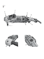
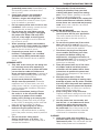
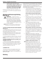
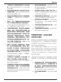
Attaching And Removing Polishing
Pads (fig. 3)
WARNING: To reduce the risk of
serious personal injury, do not allow any
loose portion of the polishing bonnet
or its attachment strings to spin freely.
Tuck away or trim any loose attachment
strings. Loose and spinning attachment
strings can entangle your fingers or snag
on the workpiece.
NOTE: Both the D6138 may use either type of
polishing pad assembly described below.
TO ATTACH POLISHING PAD WITH RUBBER BACKING
PAD (FIG. 3A)
1. To attach polishing pad (N), push the hub of the
clamp washer (M) through the hole in the center of
the polishing pad as far
as it will go.
2. Engage the hexagonal hole in the backing pad
(O). Holding the three pieces firmly together, place
the assembly on the tool spindle (I).
3. Hold the spindle lock button (E) while turning the
pads clockwise to thread them completely on the
spindle.
TO ATTACH POLISHING PAD WITH HOOK AND LOOP
BACKING PAD (FIG. 3B)
1. Attach hook and loop foam or wool pad (P) to
hook and loop backing pad (Q), being careful to
center the backing pad with the foam or wool pad.
2
. Screw backing pad (Q) onto spindle (I), while
depressing spindle lock button (E).
TO REMOVE PADS
Turn them by hand in the opposite direction from
normal rotation to allow lock button to engage
spindle, then unscrew pads in normal direction for
right-hand thread.
Polishing
These instructions and suggestions are intended to
familiarize new operators in overall general operation
of power polishing. You will develop your own
techniques which will make the job easier and faster
as you learn power polishing.
• You should use utmost care when power
polishing
around or over sharp objects and
contours of the car body. It is very important
to use the correct pressure while polishing
various sections of an automobile body. For
example, light pressure should be applied
when polishing over sharp edges of body
panels, or over edges of the rain gutter along
the top.
• Since everyone does not use the same type
of power polish, we recommend you clean
and polish a test section on a flat area of the
car first. From this test section, you can judge
the strength or cleaning action of your power
polish.
•
Remember, all power polish is not the
same. Different brands will react differently
on various painted surfaces. Also, you are
now using a power polisher with power
polish. This is entirely different from any
hand application which you may have done
before. Wash the car before power polishing
it. Washing will remove loose dirt, scum, road
salt, etc. which could act as an abrasive and
damage paint. Loose dirt, etc. will also clog
the polishing pad and you will have to clean it
more often.
• Without turning the tool on, grasp the
handles of
the tool and pick it up. Keep the
tool away from your body and depress the
trigger switch. Make sure you have a firm
grip on the handles and operate the tool
freely without forced effort or unnecessary
pressure. The side handle can be easily
changed to either side of the tool for left-
handed or right-handed operation.
NOTE: The high speed rubbing action of the
polishing bonnet upon the surface of an
automobile can build a static charge on the
metal portions of this tool. This can result
in a sensation of a very short mild electric
shock when the metal are
a of the tool is
touched, and will be more noticeable on days
when the humidity is low. This is a harmless
phenomenon but you are invited to bring
the tool to a Blacker&Decker service center
where it can be checked to assure that no
electrical malfunction is present.
(original instructions)

E N G L I S H
11
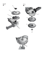
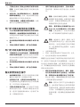
Sanding (fig. 4–7)
WARNING:
:
• Do not sand metal of any kind with your
polisher. Sparks may be generated by
sanding screws,nails or other metals which
may ignite dust particles.
• Do not wet sand with this polisher. Liquids
may enter the motor housing and cause
electricshock.
• Clean out your tool often, especially after
heavy use. Dust and grit containing metal
particlesoften accumulate on interior
surfaces and could create a risk of serious
injury, electric shock or electrocution. Wear
proper ANSI Z87.1 (CAN/CSA Z94.3) eye
protection.
• When attaching or removing abrasive disc,
use a cloth or glove to protect your hand.
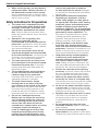
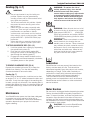
TO ATTACH AN ABRASIVE DISC (FIG. 4, 5)
1. Hold the spindle from rotating by depressing
the spindle lock button (E).
2. Push the hub of the clamp washer (M)
through the center of the sanding (R) and
also through the backing pad (O).
3. Engage the clamp washer threads on the
tool spindle and thread assembly clockwise,
completely down on the spindle.
TO REMOVE AN ABRASIVE DISC (FIG. 6)
Depress the spindle lock button (E) to keep the
spindle from rotating. Turn the disc assembly
countercl
ockwise to remove the disc.
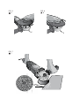
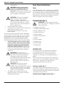
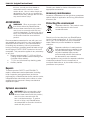
Sanding (fig. 7)
When using an abrasive disc, hold the tool so that
an angle of 10° to 15° exists between the disc and
the work. If only the outer edge of the sanding disc
is used, a rough cut will result. If the sanding disc is
pressed flat against the work, the sanding action will
be irregular and bumpy, and the tool will be difficult
to control.
Maintenance
Your Black&Decker power tool has been designed
to operate over a long period of time with a
minimum of maintenance.
Continuous satisfactory
operation depends upon proper tool care and
regular cleaning.
WARNING: To reduce the risk of
serious personal injury, turn tool off
and disconnect tool from power
source before making any adjustments
or removing/installing attachments or
accessories. Before reconnecting the
tool, depress and release the trigger
switch to ensure that the tool is off.
Cleaning
WARNING: Blow dirt and dust out of all
air vents with dry air at least once a week.
Wear proper ANSI Z87.1 (CAN/CSA
Z94.3) eye protection and proper NIOSH/
OSHA/MSHA respiratory protection when
performing this.
WARNING: Never use solvents or other
harsh chemicals for cleaning the non-
metallic parts of the tool. These chemicals
may weaken the plastic materials used in
these parts. Use a cloth dampened only
with water and mild soap. Never let any
liquid get inside the tool; never immerse
any part of the tool into a liquid.
Lubrication
Black&Decker tools are properly lubricated at the
factory and are ready for use. Tools should be
relubricated regularly every sixty days to six months,
depending on usage. (Tools used constantly on
production or heavy-duty jobs and tools exposed
to heat may require more frequent lubrication.)
This lubrication should only be attempted by
trained power tool repairpersons such as those at
Black&Decker service centers or other authorized
service locations.
Motor Brushes
Be sure tool is unplugged before inspecting brushes.
Carbon brushes should be regularly inspected for
wear. To inspect brushes, unscrew the plastic brush
inspection
caps (located in the sides of the motor
housing) and the spring and brush assemblies may
be withdrawn from the tool. Keep brushes clean and
sliding freely in their guides.
CAUTION: Only use the Black&Decker
qualified carbon brush designed for
(original instructions)

this tool, consult your local dealer or
authorized service cener for correct
carbon brush. Use of carbon brush not
designed for this tool or not qualified by
Black&Decker may damage the tool and
may result serious injury!
ACCESSORIES
WARNING: Since accessories, other
than those offered by Black&Decker,
have not been tested with this product,
use of such accessories with this tool
could be hazardous. To reduce the risk of
injury, only Black&Decker recommended
accessories should be used with this
product.
Recommended accessories for use with your tool
are available at extra cost from your local dealer or
authorized service center. If you need assistance
in locating any accessory. Use only accessories
having a maximum operating speed at least as high
as the highest “RA
TED RPM” marked on the tool’s
nameplate. This precaution applies to any accessory
on any tool.
• Rubber backing pads: 7” (18.0 cm) Quick
Change Super Flexible Rubber Backing Pad
(includes clamp washer)
• 7” (18.0 cm) hook and loop backing pads
• Auxiliary handle
Repairs
To assure product SAFETY and RELIABILITY,
repairs, maintenance and adjustments (including
brush inspection and replacement) should be
performed by a Black&Decker factory service center,
a Black&Decker authorized service center or other
qualified service personnel. Always use identical
replacement parts.
Optional accessories
WARNING: Since accessories, other
than those offered by Black&Decker,
have not been tested with this product,
use of such accessories with this
tool could be hazardous. To reduce
the risk of injury, only Black&Decker
recommended accessories should be
used with this product.
Consult your dealer for further information on the
appropriate accessories.
Accessory maintenance
Accessory maintenance at the right time guarantees
optimal results in application and a long and efficient
accessory life.
Protecting the environment
Separate collection. This product must
not be disposed of with normal
household waste.
Should you find one day that your Black&Decker
product needs replacement, or if it is of no further
use to you, do not dispose of it with household
waste. Make this product available for separate
collection.
Separate collection of used products
and packaging allows materials to be
recycled and used again. Re-use of
recycled materials helps prevent
environmental pollution and reduces
the demand for raw materials.
Local regulations may provide for separate collection
of electrical products from the household, at
municipal waste sites or by the retailer when you
purchase a new product.
12
E N G L I S H
(original instructions)

13
D6138
Black&Decker Black&Decker
D6138
220
50
1100
/ 0-600/0-3500
M14
2.85
a)
1)
2)
3)
b)
1)

14
2)
3)
4)
5)
6)
RCD
RCD
C)
1)
2)
3) /
4)
5)
6)
7)
d)
1)
2)
3)
4)
5)
6)
7)
e)
1)
a)
/
b)

简体中文
15
c) 不要使用非工具制造商推荐和专门设计的附
件。该附件即使能安装到工具上但也无法确
保安全操作。
d) 附件的额定转速必须至少达到电动工具上标
示的最大转速。附件以比其额定转速大的转
速运转会发生爆裂和飞溅。
e) 附件的外径和厚度必须在电动工具的额定能
力范围内。不正确的附件尺寸不能得到充分
防护或控制。
f) 砂轮片、法兰、靠背垫或任何其他附件的轴
孔尺寸必须适合安装到电动工具的主轴上。
与电动工具安装件不相配的带轴孔附件会失
稳、过度震动并且可能会引起失控。
g) 不要使用破损的附件。每次使用之前都要检
查附件,例如,砂轮是否有碎片和裂痕、靠
背垫是否有裂痕、撕裂或过度磨损,钢丝刷
是否松动或金属丝是否断裂。如果电动工具
或附件跌落,请检查其是否受损,或者安装
未受损的附件。检查并安装附件后,让自己
和旁观者的位置远离旋转附件的平面,并以
电动工具最大空载速度运转 1 分钟。受损附
件通常会在此测试期间碎裂。
h) 佩戴个人防护装备。根据适用情况,使用面
罩、安全护目镜或防护眼镜。适用时,戴上
防尘面罩、听力保护器、手套和能挡小磨料
或工件碎片的工作围裙。护目装备必须能够
挡住各种操作产生的飞屑。防尘面具或口罩
必须能够过滤操作产生的颗粒。长期暴露在
高强度噪声中会引起失聪。
i) 让旁观者与工作区域保持一定安全距离。任
何进入工作区域的人必须戴上防护用品。工
件或破损附件的碎片可能会飞出并导致紧邻
操作区域的旁观者受伤。
j) 若切割附件在进行操作时可能会接触到暗线
或自身电源线,则操作人员只能通过绝缘握
持面来握住电动工具。切割附件碰到一根带
电导线会使电动工具外露金属零件带电并使
操作者发生电击危险。
k) 使电线远离旋转的附件。如果控制不当,电
线可能被切断或缠绕,并使得您的手或手臂
可能被卷入旋转附件中。
l) 切勿在附件完全停止之前放下电动工具。旋
转的附件可能会抓住表面并拉动电动工具而
让您失去对工具的控制。
m) 不要在携带电动工具时开动它。意外接触旋
转附件可能会缠绕您的衣服而伤害身体。
n) 经常清理电动工具的通风口。电动机风扇会
将灰尘吸进机壳,过多的金属粉尘沉积可能
会导致电气危险。
o) 不要在易燃材料附近操作电动工具。火星可
能会点燃这些材料。
p) 不要使用需用冷却液的附件。用水或其他冷
却液可能会导致触电或电击。
所有操作的进一步安全指示
反弹和相关警告
反弹是电动工具误用和/或不正确的操作工序或条
件的结果。可以通过采取下列适当预防措施得以避
免:
a) 保持紧握电动工具,使您的身体和手臂处于
正确状态以抵抗反冲力。如有辅助手柄,则
要一直使用,以便最大限度地控制启动时的
反弹力或反力矩。如果采取合适的预防措
施,操作员就可以控制反力矩或反弹力。
b) 双手切勿靠近转动附件。附件可能会反弹碰
到手。
反弹是因卡住或缠绕住的旋转抛光盘或其他附件而
产生的突然反作用力。卡住或缠绕会引起转动附件
的迅速堵转,随之使失控的电动工具在卡住点产生
与附件转动方向相反的运动。
例如,如果抛光盘被工件缠绕或卡住,伸入卡住点
的抛光盘边缘可能会进入材料表面而引起砂轮爬出
或反弹。抛光盘可能会飞向或飞离操作员,这取决
于抛光盘在卡住点的运动方向。在这些条件下抛光
盘也可能会碎裂。

16
c)
d)
e)
a)
b)
c)
a)
b)
c)
•
ANSI Z87.1
•
•
•
ANSI
S12.6 (S3.19)
•
•
•
•
/
NIOSH/OSHA

简体中文
17
警示:处理角落的地方时需格外小心,
因为砂轮或其他附件接触次表面或表面
边缘时,抛光机可能会出现突然、猛烈
的动作。
• 您的工具上可能包含下列符号。这些符号和
定义如下所示:
请妥善保管好这些说明
电机
工具
由
的内置电机提供
电
力。确保您的电源与铭牌标记相符。超过 10% 的
电压下降会导致功率损失和过热。
D
EWALT
工具
经过出厂测试;如果工具无法运行,请检查电源。
组件(图 1)
警告:切勿改装本电动工具或其任何部
件,否则可能会导致损坏或人身伤害。
A. 调速轮
C. 变速触发开关
D. 碳刷检查口盖
E. 主轴锁按钮
F. 副手柄
G. 触发开关锁定按钮
I. 主轴
M. 夹头垫圈
O. 靠背垫
N. 抛光垫
R. 砂轮
设计用途
D6138 重型抛光机设计用于不同工作场所(例如建
筑工地)的专业抛光应用。请勿在潮湿环境中或在
有易燃液体或气体的环境中使用。
D6138 重型抛光机是专业型电动工具。不得让儿童
接触本工具。缺乏经验的操作员需要在监督下使用
本工具。
副手柄(图 1)
副手柄 (F) 随工具提供,可以安装在齿轮箱的任意
一侧。应始终使用侧手柄,以保持对工具的完全控
制。
变速触发开关(图 1)
这些工具配有一个变速触发开关,允许从 0 到 3500
转/分钟的速度控制。要启动工具,请如图 1 所示挤
压触发开关 (C),直至工具开始运转。您越用力挤压
触发器,工具便会以越快的速度运转。松开触发开
关会关闭工具。
涂抹液体蜡时请使用低速,清除风干的液体物质时
请使用高速。对汽车进行上光处理时请使用最高速
(完全按下触发开关)。如图 1 所示,通过完全挤
压触发开发并按下锁定按钮 (G),可以将工具锁定
在持续操作的状态。按住锁定按钮,同时轻轻释放
触发开关。工具将持续运转。要从锁定位置关闭工
具,请再次挤压并释放触发开发。开关锁定时不要
拔下工具的插头。插入插头时确保工具没有锁定。
如果再次插入插头时开关处于锁定位置,工具将无
法运行,直至按下锁定按钮 (G)(零压释放)。
注:触发开关仅可在工具以调速轮 (A) 指定的最高
转速运行的情况下才可以进行锁定。
调速轮(图 1)
您可以通过将调速轮 (A) 旋转到所需设置,更改工
具的最大速度。调速轮整合了制动器,可以防止调
速轮意外移动,同时方便选择速度。为了提供更多
功能性,可以单独通过调速轮 (A) 将触发开关锁定
在完全按下的位置,改变工具转速。电子变速控制
器不但能让您选择符合工作需要的速度,还可以维
工具上的标签
您的工具上可能包含下列符号:
参阅说明手册
使用护目设备
II级结构
Black&Decker
Black&Decker
已

18
(A) 600 3500 /
0
2200 / 0 2200
/
600 /
0 600 /
2200 /
2200 /
1. (C)
2. 2600 /
3000 /
2400 /
2000 /
D6138 2400 /
1
/
(E)
/
D6138 6 7 915.2 17.8
22.9 cm
3
D6138
3A
1. (N) (M)
2. (O)
(I)
3. (E)
3B
1. (P) (Q)
2. (Q) (I)
(E)
Page is loading ...
Page is loading ...
Page is loading ...
Page is loading ...
-
 1
1
-
 2
2
-
 3
3
-
 4
4
-
 5
5
-
 6
6
-
 7
7
-
 8
8
-
 9
9
-
 10
10
-
 11
11
-
 12
12
-
 13
13
-
 14
14
-
 15
15
-
 16
16
-
 17
17
-
 18
18
-
 19
19
-
 20
20
-
 21
21
-
 22
22
-
 23
23
-
 24
24


Ask a question and I''ll find the answer in the document
Finding information in a document is now easier with AI
Related papers
Other documents
-
Hitachi SP18VA Owner's manual
-
Black & Decker BDGP1518 User manual
-
Global Machinery Company POL1450M User manual
-
Draper 125mm Dual Action Polisher Operating instructions
-
-
MAC TOOLS MCM849 User manual
-
Drill Master 60626 Owner's manual
-
-
-
Harbor Freight Tools 7 in. 10 Amp Variable Speed Polisher User manual