Hitachi RAC-65NH5 User manual

Category
Split-system air conditioners
Type
User manual

This manual is also suitable for

NO. 0304E
SPECIFICATIONS AND PARTS ARE SUBJECT TO CHANGE FOR IMPROVEMENT
ROOM AIR CONDITIONER
INDOOR UNIT + OUTDOOR UNIT
DECEMBER 2005
Refrigeration & Air-Conditioning Divi-
SERVICE MANUAL
PM
REFER TO THE FOUNDATION MANUAL
TECHNICAL INFORMATION
FOR SERVICE PERSONNEL ONLY
(W)
(A)
(kW)
(B.T.U./h)
(W)
(A)
(kW)
(B.T.U./h)
W
H
D
(kg)
RAK-65NH5 RAC-65NH5
DC INVERTER (WALL TYPE)
TYPE
MODEL
POWER SOURCE
TOTAL INPUT
TOTAL AMPERES
CAPACITY
TOTAL INPUT
TOTAL AMPERES
CAPACITY
DIMENSIONS
(mm)
NET WEIGHT
SPECIFICATIONS
1,030
295
191
12
RAK-65NH5
CONTENTS
SPECIFICATIONS ------------------------------------------------------------------- 4
HOW TO USE ------------------------------------------------------------------------ 6
CONSTRUCTION AND DIMENSIONAL DIAGRAM --------------------- 28
MAIN PARTS COMPONENT --------------------------------------------------- 30
WIRING DIAGRAM ---------------------------------------------------------------- 33
CIRCUIT DIAGRAM --------------------------------------------------------------- 35
PRINTED WIRING BOARD LOCATION DIAGRAM --------------------- 41
BLOCK DIAGRAM ----------------------------------------------------------------- 43
BASIC MODE ----------------------------------------------------------------------- 45
REFRIGERATING CYCLE DIAGRAM --------------------------------------- 59
AUTO SWING FUNCTION ------------------------------------------------------ 60
DESCRIPTION OF MAIN CIRCUIT OPERATION ----------------------- 61
SERVICE CALL Q & A ---------------------------------------------------------- 92
TROUBLE SHOOTING ----------------------------------------------------------- 95
PARTS LIST AND DIAGRAM ------------------------------------------------- 115
RAK-65NH5 / RAC-65NH5
RAC-65NH5
COOLING
HEATING
INDOOR UNIT
OUTDOOR UNIT
2,300
10.60 ~ 9.70
6.05 (0.90 ~ 6.50)
20,660
2,400
11.00 ~ 10.10
7.05 (0.90 ~ 9.00)
24,060
After installation
1 PHASE, 50 Hz, 220 ~ 240V
850
650
298
45
SAFETY DURING REPAIR WORK
1. In order to disassemble and repair
the unit in question, be sure to
disconnect the power cord plug
from the power outlet before starting
the work.
2. If it is necessary to replace any parts, they should be replaced with respective genuine parts for the unit, and
the replacement must be effected in correct manner according to the instructions in the Service Manual of
the unit.
If the contacts of electrical parts
are defective, replace the
electrical parts without trying to
repair them.
3. After completion of repairs, the initial state
should be restored.
4. Lead wires should be connected and laid as
in the initial state.
5. Modification of the unit by user himself should
absolutely be prohibited.
6. Tools and measuring instruments for use in repairs or inspection should be accurately calibrated in advance.
7. In installing the unit having been repaired, be careful to prevent the occurence of any accident such as
electrical shock, leak of current, or bodily injury due to the drop of any part.
8. To check the insulation of the unit, measure the insulation resistance between the power cord plug and
grounding terminal of the unit. The insulation resistance should be 1M
or more as measured by a 500V
DC megger.
9. The initial location of installation such as window, floor or the other should be checked for being and safe
enough to support the repaired unit again.
If it is found not so strong and safe, the unit should be installed at the initial location reinforced or at a new
location.
10. Any inflammable thing should never
be placed about the location of
installation.
11. Check the grounding to see whether
it is proper or not, and if it is found
improper, connect the grounding
terminal to the earth.
DANGER
First, I must disconnect
the power cord plug
from the power outlet.
– i –
WORKING STANDARDS FOR PREVENTING BREAKAGE OF SEMICONDUCTORS
1. Scope
The standards provide for items to be generally observed in carrying and handling semiconductors in relative
manufacturers during maintenance and handling thereof. (They apply the same to handling of abnormal goods
such as rejected goods being returned).
2. Object parts
(1) Micro computer
(2) Integrated circuits (IC)
(3) Field-effect transistors (FET)
(4) P.C. boards or the like on which the parts mentioned in (1) and (2) of this paragraph are equipped.
3. Items to be observed in handling
(1) Use a conductive container for carrying and storing of parts. (Even rejected goods should be handled in
the same way).
Fig. 1. Conductive Container
(2) When any part is handled uncovered (in counting, packing and the like), the handling person must always
use himself as a body earth. (Make yourself a body earth by passing one M ohm earth resistance through
a ring or bracelet).
(3) Be careful not to touch the parts with your clothing when you hold a part even if a body earth is being
taken.
(4) Be sure to place a part on a metal plate with grounding.
(5) Be careful not to fail to turn off power when you repair the printed circuit board. At the same time, try
to repair the printed circuit board on a grounded metal plate.
1M
Fig. 2. Body Earth
Body earth
(Elimik conductive band)
Clip for connection with a
grounding wire
IC
A conductive polyvinyl bag
IC
Conductive sponge
– 1 –
– 2 –
Metal plate
(of Al. stainless steel, etc.)
Working table
Resistor 1M
(1/2W)
Earth wire
Staple
Bare copper wire
(for body earth)
Fig. 3 Grounding of the working table
(6) Use a three wire type soldering iron including a grounding wire.
Use a high insulation mode (100V, 10M or higher) when ordinary iron is to be used.
(7) In checking circuits for maintenance, inspection, or some others, be careful not to have the test probes
of the measuring instrument shortcircuit a load circuit or the like.
Soldering iron
Grounding wire
Screw stop at the screwed
part using a rag plate
Fig. 4 Grounding a solder iron
1. In quiet or stopping operation, slight flowing noise of refrigerant in the refrigerating cycle is heard occasionally,
but this noise is not abnormal for the operation.
2. When it thunders near by, it is recommend to stop the operation and to disconnect the power cord plug
from the power outlet for safety.
3. In the event of power failure, the air conditioner will restart automatically in the previously selected mode
once the power is restored. In the event of power failure during TIMER operation, the timer will be reset and
the unit will begin or stop operating under a new timer setting.
4. If the room air conditioner is stopped by adjusting thermostat, or missoperation, and re-start in a moment,
there is occasion that the cooling and heating operation does not start for 3 minutes, it is not abnormal
and this is the result of the operation of IC delay circuit. This IC delay circuit ensures that there is no
danger of blowing fuse or damaging parts even if operation is restarted accidentally.
5. This room air conditioner should not be used at the cooling operation when the outside temperature is
below -10°C (14°F).
6. This room air conditioner (the reverse cycle) should not be used when the outside temperature is below
–15°C (5°F).
If the reverse cycle is used under this condition, the outside heat exchanger is frosted and efficiency falls.
7. When the outside heat exchanger is frosted, the frost is melted by operating the hot gas system, it is not
trouble that at this time fan stops and the vapour may rise from the outside heat exchanger.
!
CAUTION
– 3 –
SPECIFICATIONS
MODEL
FAN MOTOR
FAN MOTOR CAPACITOR
FAN MOTOR PROTECTOR
COMPRESSOR
COMPRESSOR MOTOR CAPACITOR
OVERLOAD PROTECTOR
OVERHEAT PROTECTOR
FUSE (for MICROPROCESSOR)
POWER RELAY
POWER SWITCH
TEMPORARY SWITCH
SERVICE SWITCH
TRANSFORMER
VARISTOR
NOISE SUPPRESSOR
THERMOSTAT
REMOTE CONTROL SWITCH (LIQUID CRYSTAL)
RAK-65NH5
PWM DC35V
NO
NO
NO
NO
NO
NO
NO
NO
YES
NO
NO
NO
NO
YES(IC)
YES
----------
40 W
NO
NO
NO
YES (INTERNAL)
YES
3.0A
G4A
NO
NO
YES
NO
450NR
YES
YES(IC)
NO
1420g
WITHOUT REFRIGERANT BECAUSE
COUPLING IS FLARE TYPE.
UNIT
PIPES (MAX. 30m)
REFRIGERANT CHARGING
VOLUME
(Refrigerant R410A)
RAC-65NH5
JU1013D5
– 4 –
Chargeless upto 20m, above 20m upto max 30m, charge refrigerant R410A 5 g/m.
– 5 –
above 50mm
above 100mm
above
0.45m
above 300mm
must not bend
above 100mm
2,300mm or more
Maximum pipe length 30m
Minimum pipe length 5m
above 200mm
above 700mm
above 200mm
above 50mm when
installed on the
ceiling of balcony
(
)
above 100mm
above 100mm
give clearance as
wide as possible
Plug
The difference in height
between the indoor and
outdoor unit should be kept
max 10m.
The connecting pipe, no
matter big or small, should
all be insulated with
insulation pipe and then
wrapped with vinyl tape. (The
insulator will deteriorate if it
is not wrapped with tape).
The connection of insulated
drain hose.
Please use insulated drain
hose for the indoor piping
(commercial product).
The indoor piping should be
insulated with the enclosed
insulation pipe. (If the insulator
is insufficient, please use
commersial products).
Be sure to
completely seal
any gap with putty.
CAUTION
The installation height of indoor unit must be 2.3m or more.
!
Figure showing the installation of Indoor and Outdoor unit
– 6 –
!
SAFETY PRECAUTION
Please read the “Safety Precaution” carefully before operating the unit to ensure correct usage of the unit.
Pay special attention to signs of “ Warning” and “ Caution”. The “Warning” section contains matters which,
if not observed strictly, may cause death or serious injury. The “Caution” section contains matters which may
result in serious consequences if not observed properly. Please observe all instructions strictly to ensure safety.
The sign indicate the following meanings.
Please keep this manual after reading.
WARNING
PRECAUTIONS DURING INSTALLATION
Do not reconstruct the unit.
Water leakage, fault, short circuit or fire may occur if you reconstruct the
unit by yourself.
Please ask your sales agent or qualified technician for the installation of
your unit. Water leakage, short circuit or fire may occur if you install the unit
by yourself.
Please use earth line.
Do not place the earth line near water or gas pipes, lightning-conductor, or
the earth line of telephone. Improper installation of earth line may cause
electric shock.
A circuit breaker should be installed depending on the mounting site of the
unit. Without a circuit breaker, the danger of electric shock exists.
Do not install the unit near a location where there is flammable gas. The
outdoor unit may catch fire if flammable gas leaks around it.
Please ensure smooth flow of water when installing the drain hose.
CAUTION
!
!
PRECAUTIONS DURING SHIFTING OR MAINTENANCE
Should abnormal situation arises (like burning smell), please stop operating the unit
and turn off the circuit breaker. Contact your agent. Fault, short circuit or fire may
occur if you continue to operate the unit under abnormal situation.
Please contact your agent for maintenance. Improper self maintenance may cause
electric shock and fire.
Please contact your agent if you need to remove and reinstall the unit. Electric
shock or fire may occur if you remove and reinstall the unit yourself improperly.
!
Make sure to connect earth line.
Indicates the instructions that must be followed.
The sign in the figure indicates prohibition.
W
A
R
N
I
N
G
!
PRECAUTIONS DURING OPERATION
Avoid an extended period of direct air flow for your health.
W
A
R
N
I
N
G
!
Do not insert a finger, a rod or other objects into the air outlet or inlet. As the fan
is rotating at a high speed, it will cause injury. Before cleaning, be sure to stop the
operation and turn the breaker OFF.
During thunder storm, disconnect and turn off the circuit breaker.
Do not use any conductor as fuse wire, this could cause fatal accident.
– 7 –
PRECAUTIONS DURING OPERATION
Do not attempt to operate the unit with wet hands, this could cause fatal
accident.
When operating the unit with burning equipments, regularly ventilate the
room to avoid oxygen insufficiency.
Do not direct the cool air coming out from the air-conditioner panel to face
household heating apparatus as this may affect the working of apparatus
such as the electric kettle, oven etc.
Do not use any aerosol or hair sprays near the indoor unit. This chemical
can adhere on heat exchanger fin and blocked the evaporation water flow
to drain pan. The water will drop on tangential fan and cause water splashing
out from indoor unit.
Please ensure that outdoor mounting frame is always stable, firm and
without defect. If not, the outdoor unit may collapse and cause danger.
Do not splash or direct water to the body of the unit when cleaning it as this
may cause short circuit.
When operating the unit with the door and windows opened, (the room humidity is always above
80%) and with the air deflector facing down or moving automatically for a long period of time,
water will condense on the air deflector and drips down occasionally. This will wet your furniture.
Therefore, do not operate under such condition for a long time.
If the amount of heat in the room is above the cooling or heating capability of the unit (for
example: more people entering the room, using heating equipments and etc.), the preset room
temperature cannot be achieved.
This appliance is not intended for use by young children or infirm persons unless they have been
adequately supervised by a responsible person to ensure that they can use the appliance safely.
Young children should be supervised to ensure that they do not play with the appliance.
Do not climb on the outdoor unit or put objects on it.
Please switch off the unit and turn off the circuit breaker during cleaning, the
high-speed fan inside the unit may cause danger.
Turn off the circuit breaker if the unit is not to be operated for a long period.
C
A
U
T
I
O
N
!
The product shall be operated under the manufacturer specification and
not for any other intended use.
Do not put water container (like vase) on the indoor unit to avoid water
dripping into the unit. Dripping water will damage the insulator inside the unit
and causes short-circuit.
Do not place plants directly under the air flow as it is bad for the plants.
– 8 –
INDOOR UNIT
NAMES AND FUNCTIONS OF EACH PART
Air filter
To prevent dust from coming into the indoor unit.
(Refer page 25)
Front panel
Indoor unit indicators
Light indicator showing the operating condition.
(Refer page 9)
Horizontal deflector
Vertical deflector
(Air Outlet)
(Refer page 20)
Remote controller
Send out operation signal to the indoor unit. So as to
operate the whole unit.
(Refer page 10)
Drain pipe
Condensed water drain to outside.
Connecting cord and insulation pipe for piping
Air inlet (Back and Left side)
Air outlet
WIDTH (mm)
1030
850
MODEL
RAK-65NH5
RAC-65NH5
HEIGHT (mm)
295
650
DEPTH (mm)
191
298
MODEL NAME AND DIMENSIONS
OUTDOOR UNIT
CAUTION
When heating operation, drain or
defrosted water flows out from outdoor
unit. Don’t close drain outlet portion
in chilly area so as not to freeze these.
!
– 9 –
INDOOR UNIT INDICATORS
TEMPORARY SWITCH
Use this switch to start and stop when the remote controller does not work.
By pressing the temporary switch, the operation is done in automatic mode.
OPERATION INDICATOR
This figure shows the opening condition of
front panel. Refer to page 23 in relation to
how to open or close the front panel.
FILTER LAMP
When the device is operated for a total of about 200
hours, the FILTER lamp lights to indicate that it is time
to clean the filter. The lamp goes out when the
“ (AUTO SWING)” button is pressed while the
device is on “STANDBY MODE”.
OPERATION LAMP
This lamp lights during operation.
The OPERATION LAMP flashes in the following cases
during heating.
(1) During preheating
For about 2–3 minutes after starting up.
(2) During defrosting
Defrosting will be performed about once an hour
when frost forms on the heat exchanger of the
outdoor unit, for 5–10 minutes each time.
TIMER LAMP
This lamp lights when the timer is working.
HITACHI
TEMPORARY
SWITCH
TEMPORARY
SWITCH
10
AUTO
HEAT
DEHUMIDIFY
COOL
FAN
FAN SPEED
LOW
MED
HI
SLEEPING
STOP (CANCEL)
START (RESERVE)
START/STOP
TIME
TIMER SET
TIMER SELECTOR
ON TIMER
OFF TIMER
AUTO SWING
˚
CH
RESET
˚
CH
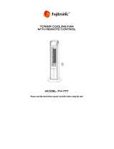
NAMES AND FUNCTIONS OF REMOTE CONTROL UNIT
REMOTE CONTROLLER
This controls the operation of the indoor unit. The range of control is about 7 meters. If indoor lighting is controlled
electronically, the range of control may be shorter.
This unit can be fixed on a wall using the fixture provided. Before fixing it, make sure the indoor unit can be controlled
from the remote controller.
Handle the remote controller with care. Dropping it or getting it wet may compromise its signal transmission capability.
After new batteries are inserted into the remote controller, the unit will initially require approximately 10 seconds to
respond to commands and operate.
Signal emitting window/transmission sign
Point this window toward the indoor unit when controlling it.
The transmission sign blinks when a signal is sent.
Display
This indicates the room temperature selected, current time, timer status, function
and intensity of circulation selected.
START/STOP button
Press this button to start operation. Press it again to stop operation.
SLEEP button
Use this button to set the sleep timer.
TEMPERATURE buttons
Use these buttons to raise or lower the temperature setting. (Keep pressed, and
the value will change more quickly.)
TIME button
Use this button to set and check the time and date.
RESET buttons
FUNCTION selector
Use this button to select the operating mode. Every time you press it,
the mode will change from (AUTO) to (HEAT) to (DEHUMIDIFY) to
(COOL) and to (FAN) cyclically.
FAN SPEED selector
This determines the fan speed. Every time you press this button, the intensity
of circulation will change from (AUTO) to (HI) to (MED) to (LOW)
(This button allows selecting the optimal or preferred fan speed for each operation
mode).
AUTO SWING button
Controls the angle of the horizontal air deflector.
TIMER control
Use this button to set the timer.
OFF-TIMER button Select the turn OFF time.
ON-TIMER button Select the turn ON time.
RESERVE button Time setting reservation.
CANCEL button Cancel time reservation.
Precautions for Use
Do not put the remote controller in the following places.
Under direct sunlight.
In the vicinity of a heater.
Handle the remote controller carefully. Do not drop it on the floor,
and protect it from water.
Once the outdoor unit stops, it will not restart for about 3 minutes
(unless you turn the power switch off and on or unplug the power
cord and plug it in again).
This is to protect the device and does not indicate a failure.
If you press the FUNCTION selector button during operation, the
device may stop for about 3 minutes for protection.
11
AUTOMATIC OPERATION
The device will automatically determine the mode of operation, HEAT, COOL or DEHUMIDIFY depending on
the current room temperature. The selected mode of operation will change when the room temperature varies.
As the settings are stored in memory in the remote controller, you only have to
press the (START/STOP) button next time.
Press the FUNCTION selector so that the display indicates the (AUTO) mode
of operation.
When AUTO has been selected, the device will automatically determine the
mode of operation, HEAT, COOL or DEHUMIDIFY depending on the current
room temperature.
If the mode automatically selected by the unit is not satisfactory, manually
change the mode setting (heat, dehumidify, cool or fan).
Press the (START/STOP) button.
Operation starts with a beep.
Press the button again to stop operation.
You can raise or lower the temperature setting as necessary by maximum of 3°C.
Press the temperature button and the temperature setting will
change by 1°C each time.
The preset temperature and the actual room temperature may vary somewhat
depending on conditions.
The display does not indicate the preset temperature in the AUTO mode. If you
change the setting, the indoor unit will produce a beep.
1
°C
RESET
Press the (FAN SPEED) button, AUTO and LOW is available.
VARIOUS FUNCTIONS
Auto Restart Control
If there is a power failure, operation will be automatically restarted when the power is resumed with previous
operation mode and airflow direction.
(As the operation is not stopped by remote controller.)
If you intend not to continue the operation when the power is resumed, switch off the power supply.
When you switch on the circuit breaker, the operation will be automatically restarted with previous operation
mode and airflow direction.
Note: 1. If you do not require Auto Restart Control, please consult your sales agent or OFF by remote
control.
2. Auto Restart Control is not available when Timer or Sleep Timer mode is set.
START
STOP
12
HEATING OPERATION
Use the device for heating when the outdoor temperature is under 21°C.
When it is too warm (over 21°C), the heating function may not work in order to protect the device.
In order to keep reliability of the device, please use this device above 15°C of the outdoor temperature.
Press the FUNCTION selector so that the display indicates
(HEAT).
Set the desired FAN SPEED with the (FAN SPEED) button
(the display indicates the setting).
(AUTO): The fan speed is HI at first and varies to
MED or LOW automatically when the preset
temperature has been reached.
(HI) : Economical as the room will become warm
quickly.
But you may feel a chill at the beginning.
(MED) : Fan speed slow.
(LOW) : Fan speed slower.
Set the desired room temperature with the TEMPERATURE
buttons (the display indicates the setting).
The temperature setting and the actual room temperature may
vary somewhat depending on conditions.
Press the (START/STOP) button. Heating operation starts
with a beep. Press the button again to stop operation.
As the settings are stored in memory in the remote controller, you only
have to press the (START/STOP) button next time.
1
2
3
START
STOP
˚
C
RESET
˚
C
13
DEHUMIDIFYING OPERATION
Use the device for dehumidifying when the room temperature is over 16°C.
When it is under 15°C, the dehumidifying function will not work.
Dehumidifying Function
When the room temperature is higher than the temperature setting: The device will dehumidify the room,
reducing the room temperature to the preset level.
When the room temperature is lower than the temperature setting: Dehumidifying will be performed at
the temperature setting slightly lower than the current room temperature, regardless of the temperature
setting. The function will stop (the indoor unit will stop emitting air) as soon as the room temperature
becomes lower than the setting temperature.
Set the desired room temperature with the TEMPERATURE
button (the display indicates the setting).
The range of 20-26˚C is recommended as
the room temperature for dehumidifying.
Press the (START/STOP) button. Dehumidifying operation
starts with a beep. Press the button again to stop operation.
2
As the settings are stored in memory in the remote controller, you
only have to press the
(START/STOP) button next time.
START
STOP
Press the FUNCTION selector so that the display indicates
(DEHUMIDIFY).
The FAN SPEED is set at LOW automatically.
The FAN SPEED button does not work.
1
RESET
˚
C
˚
C
14
˚
C
RESET
˚
C
COOLING OPERATION
Use the device for cooling when the outdoor temperature is -10~43°C.
If in doors humidity is very high (80%), some dew may form on the air outlet grille of the indoor unit.
Press the FUNCTION selector so that the display indicates
(COOL).
Set the desired FAN SPEED with the
(FAN SPEED) button
(the display indicates the setting).
(AUTO): The FAN SPEED is HI at first and varies to
MED or LOW automatically when the preset
temperature has been reached.
(HI) : Economical as the room will become cool
quickly.
(MED) : Fan speed slow.
(LOW) : Fan speed slower.
Set the desired room temperature with the TEMPERATURE
button (the display indicates the setting).
The temperature setting and the actual room temperature may
vary some how depending on conditions.
Press the
(START/STOP) button. Cooling operation starts
with a beep. Press the button again to stop operation. The
cooling function does not start if the temperature setting is
higher than the current room temperature (even though the
(OPERATION) lamp lights). The cooling function will start as
soon as you set the temperature below the current room
temperature.
As the settings are stored in memory in the remote controller, you
only have to press the
(START/STOP) button next time.
1
2
START
STOP
3
15
FAN SPEED (AUTO)
.....
When the AUTO fan speed mode is set in the cooling/heating operation:
For the heating operation
The fan speed will automatically change according to the temperature
of discharged air.
When the difference of room temperature and setting temperature is
large, fan starts to run at HI speed.
When the room temperature reaches setting temperature, fan speed
changes to LOW automatically.
When the difference of room temperature and setting temperature is
large, fan starts to run at HI speed.
After room temperature reaches the preset temperature, the cooling
operation, which changes the fan speed and room temperature to obtain
optimum conditions for natural healthful cooling will be performed.
For the cooling operation
FAN OPERATION
You can use the device simply as an air circulator. Use this function to dry the interior of the indoor
unit at the end of summer.
Press the FUNCTION selector so that the display indicates
(FAN).
Press the (FAN SPEED) button.
Press the (START/STOP) button. Fan operation starts with
a beep. Press the button again to stop operation.
1
2
START
STOP
RESET
16
HOW TO SET THE TIMER
ON/OFF-Timer
The device will turn on (off) and off
(on) at the designated times.
The switching occurs first at the
preset time that comes earlier.
The arrow mark appearing on the
display indicates the sequence of
switching operations.
1
Press the (ON-OFF)
button so that the (OFF)
mark blinks.
OFF-Timer
You can set the device to turn off
at the present time.
After you change the
batteries;
How to Cancel Reservation
Point the signal window of the remote controller toward the indoor unit, and press the (CANCEL)
button.
The (RESERVED) sign goes out with a beep and the (TIMER) lamp turns off on the indoor unit.
1
Set the current month and
day with the TIMER control
button.
1
Press the (OFF-TIMER)
button. The (OFF) mark blinks
on the display.
1
Press the (ON-TIMER)
button the (ON) mark blinks
on the display.
2
Set the turn-off time
with the TIMER control
button.
Press the (RESERVE)
button.
3
Press the (ON-
TIMER) button so that the
(OFF) mark lights and
the (ON) mark blinks.
NOTE
You can set only one of the OFF-timer,
ON-timer and ON/OFF-timer.
ON-Timer
Time, Day, Month
The device will turn on
at the designated times.
TIME, DAY,
MONTH
(current time,
day, month)
OFF TIMER
ON TIMER
RESERVE
CANCEL
M D
M D
AM
STOP
Start
AM
Start
Stop
PM
Start Stop
PM
AM
PM
RESET
17
3
Point the signal window of the remote controller toward the indoor unit, and
press the (RESERVE) button.
The (OFF) mark starts lighting instead of flashing and the sign (RESERVED)
lights. A beep occurs and the (TIMER) lamp lights on the indoor unit.
The time indication will disappear
automatically in 10 second.
To check the current time setting,
press the (TIME) button twice.
The setting of the current time is
now complete.
The timer may be used in three ways: off-timer, on-timer, and ON/OFF (OFF/ON)-timer. Set
the current time at first because it serves as a reference.
As the time settings are stored in memory in the remote controller, you only have to press
the (RESERVE) button in order to use the same settings next time.
2
Press the
(TIME) button.
3
Set the current time with the
TIMER control button.
Example: The current time is 1:30 p.m.
2
Set the turn-off time with the
TIMER control button.
The setting of turn-off time is now complete.
Example: The device will turn off at 11:00p.m.
Example:
The device will turn on at 7:00 a.m.
The setting of the turn-on time is now complete.
4
Set the turn-on time with the
TIMER control button.
5
Point the signal window of the remote controller toward the indoor unit, and
press the (RESERVE) button.
The (ON) mark starts lighting instead of flashing and the (RESERVED) sign
lights. A beep occurs and the (TIMER) lamp lights on the indoor unit.
3
Point the signal window of the remote controller toward the indoor unit, and
press the (RESERVE) button.
The (ON) mark starts lighting instead of flashing and the (RESERVED) sign
lights. A beep occurs and the (TIMER) lamp lights on the indoor unit.
2
Set the turn-on time with the
TIMER control button.
Example:
The device will turn off at 10:30 p.m. and it will be turn on
at 7:00 a.m.
The settings of the turn-on/off times are now complete.
4
Press the (TIME) button again.
The time indication starts lighting
instead of flashing.
PM PM
AM
PM
PM
PM
AM
AM
AM
AM
PM
PM
18
HOW TO SET THE SLEEP TIMER
1
Set the ON-timer.
Set the current time at first if it is not set before (see the pages for setting
the current time). Press the (SLEEP) button, and the display changes as
shown below.
Mode
Sleep timer
Indication
1 hour 2 hours 3 hours 7 hours
Sleep timer off
44 44
1
Sleep Timer: The device will continue working for the designated
number of hours and then turn off.
Point the signal window of the remote controller toward the indoor
unit, and press the SLEEP button.
The timer information will be displayed on the remote controller.
The TIMER lamp lights with a beep from the indoor unit. When the
sleep timer has been set, the display indicates the turn-off time.
Example: If you set 3 hours sleep
time at 11:38 p.m., the turn-off
time is 2:38 a.m.
2
Press the (SLEEP) button and set the sleep timer.
The device will be turned off by the sleep
timer and turned on by on-timer.
How to Cancel Reservation
Point the signal window of the remote controller toward the indoor unit, and press the (CANCEL)
button.
The (RESERVED) sign goes out with a beep and the (TIMER) lamp turns off on the indoor unit.
For heating:
In this case, the device will turn off
in 2 hours (at 1:38 a.m.) and turn
on early so that the preset
temperature will be almost reached
at 6:00 next morning.
SLEEP
H
H
AM
AM
Sleep
timer
Start
H
If date or current time is not set, sleep timer can not be set.
If you set the sleep timer after the off-, on/off- or off/on-timer has been set, the sleep timer becomes
effective instead of the off-, on/off- or off/on-timer set earlier.
You can not set other timer during sleep timer operation.
After sleep timer time is up and when press sleep button again, the sleep timer will be set as last setting.
Sleep timer effective only once.
NOTE
  • Page 1 1
  • Page 2 2
  • Page 3 3
  • Page 4 4
  • Page 5 5
  • Page 6 6
  • Page 7 7
  • Page 8 8
  • Page 9 9
  • Page 10 10
  • Page 11 11
  • Page 12 12
  • Page 13 13
  • Page 14 14
  • Page 15 15
  • Page 16 16
  • Page 17 17
  • Page 18 18
  • Page 19 19
  • Page 20 20
  • Page 21 21
  • Page 22 22
  • Page 23 23
  • Page 24 24
  • Page 25 25
  • Page 26 26
  • Page 27 27
  • Page 28 28
  • Page 29 29
  • Page 30 30
  • Page 31 31
  • Page 32 32
  • Page 33 33
  • Page 34 34
  • Page 35 35
  • Page 36 36
  • Page 37 37
  • Page 38 38
  • Page 39 39
  • Page 40 40
  • Page 41 41
  • Page 42 42
  • Page 43 43
  • Page 44 44
  • Page 45 45
  • Page 46 46
  • Page 47 47
  • Page 48 48
  • Page 49 49
  • Page 50 50
  • Page 51 51
  • Page 52 52
  • Page 53 53
  • Page 54 54
  • Page 55 55
  • Page 56 56
  • Page 57 57
  • Page 58 58
  • Page 59 59
  • Page 60 60
  • Page 61 61
  • Page 62 62
  • Page 63 63
  • Page 64 64
  • Page 65 65
  • Page 66 66
  • Page 67 67
  • Page 68 68
  • Page 69 69
  • Page 70 70
  • Page 71 71
  • Page 72 72
  • Page 73 73
  • Page 74 74
  • Page 75 75
  • Page 76 76
  • Page 77 77
  • Page 78 78
  • Page 79 79
  • Page 80 80
  • Page 81 81
  • Page 82 82
  • Page 83 83
  • Page 84 84
  • Page 85 85
  • Page 86 86
  • Page 87 87
  • Page 88 88
  • Page 89 89
  • Page 90 90
  • Page 91 91
  • Page 92 92
  • Page 93 93
  • Page 94 94
  • Page 95 95
  • Page 96 96
  • Page 97 97
  • Page 98 98
  • Page 99 99
  • Page 100 100
  • Page 101 101
  • Page 102 102
  • Page 103 103
  • Page 104 104
  • Page 105 105
  • Page 106 106
  • Page 107 107

Hitachi RAC-65NH5 User manual

Category
Split-system air conditioners
Type
User manual
This manual is also suitable for

Ask a question and I''ll find the answer in the document

Finding information in a document is now easier with AI