Page is loading ...

12-2013
ASSEMBLY INSTRUCTIONS
SIX DRAWER BASE CABINET
HEAVY DUTY
STEEL CABINET
16

Part No Description Qty Image
SB-14
Cabinet
Body
1
DW-180
Large
Drawer
2
DW-90
Small
Drawer
4
LK-001
Lock
1
KEY-001
Keys
2
LINER
Drawer
Liner
6
Part No Description Qty Image
SLD-01
20 inch
Full Extend
Slides
16
Handle
Screws
Screws
Washers
24
24
AP-DW
Full Length
Handles
6
M6-20
Hex Bolt for
Connecting
Cabinets
Together
4
6 mm
Hex Nut
4
25 mm
1 inch
Fender
Washer
4
50 mm
2 inch
Drywall
Screw
4
SIX DRAWER BASE CABINET
Parts List
Page 2

Six Drawer Base Cabinet Hardware
4 Wood Screws
4 Large Washers
4 6MM Nuts
4 M6-20 Bolts
24 Handle Screws
24 Handle Washers
6 Aluminum Drawer Pulls
Page 3
Lock & Keys
Number 001

Six Drawer Base Cabinet
TOOLS REQUIRED
Phillips Screw Driver
10 mm Ratchet/Socket
Thoroughly Clean the Assembly Area
Remove Personal Items that Can Scratch the Cabinet Finish - Watches, Belt, Rings, etc.
Open Cartons Carefully to Avoid Damaging Cabinet Panels
Compare Carton Contents with Parts List Count
Use the Shipping Cartons for the Assembly Surface - Do Not Assemble on Concrete
If Using a Cordless Drill for Assembly - Dial Drill Torque to a Low Setting
STEP 1 - continued on next page
Tape Measure
Page 4
10 mm Open End Wrench
BEFORE YOU BEGIN:
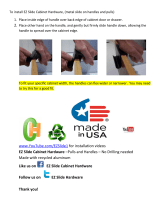
Remove All Drawers From Cabinet - Important Note - Sometimes the rubber keepers on the
drawer slides will make the drawers feel like they are locked. Place a flat head screwdriver between the
side of the drawer and the side panel and Gently Pry. Drawer will pop open.
Label and number each drawer (1 through 6) with masking tape. Open Top Drawer to fully extended
position. Push down on Right Drawer Slide release levers and push slide bodies towards cabinet. Re-
peat the procedure on the Left Drawer Slides. If Drawer does not release from slide, reverse the proce-
dure, pulling up on the right lever and pushing down on the left lever. Remove Drawer from slide and
cabinet body. Repeat procedure for remaining 5 Drawers.
Note Lever
Release May Be
reversed
Right Drawer Slide
Push Down on
Release Lever

Six Drawer Base Cabinet
STEP 1 - continued
Label Each Drawer
Page 5
Remove Drawers from Cabinet Body
1
6
3
2
4
5

Six Drawer Base Cabinet
Page 6
Attach Aluminum Pulls securely to Drawer
Face with Machine Screws. Repeat for all
remaining drawers
STEP 2
Aluminum Pull Parts Magnum
6 x Aluminum Pulls AP-DW
24 x Machine Screws
24 x Washers
IMPORTANT NOTE
Do Not Store Keys in Cabinet
If keys are locked in cabinet after assembly, drawers can be opened by turning
the cabinet upside down. This will release the slide locking mechanism and all
drawers can be opened to retrieve keys. Once cabinet has been mounted to
wall or loaded with tools do not store keys in the cabinet drawer.

Page 7
Six Drawer Base Cabinet
Move cabinet into its final position. Fasten
cabinet to wall STUDS and/or adjacent cabi-
nets as
required.
Adjacent Cabinet Mount Parts
4 x M6-20 Hex Head Bolts
4 x 6 mm Hex Nuts
STEP 3
Wall Mount Parts
4 x Drywall Screws
4 x Fender Washers
STEP 4
Insert large drawers into cabinet body by extending all 4 slides. Insert the 4
Drawer Slides into these extended slides. Push drawer inward in a gentle
rocking motion. When slides are properly inserted you will hear a clicking
sound.
Close and re-open drawer. Drawer should slide freely. If drawer binds, one
or more slides was probably not correctly aligned during drawer insertion.
NEVER FORCE SLIDES
Installing drawers with double slides can be tricky. If you encounter resistance,
check alignment and repeat above instructions. In some cases it may be easier to
first attach the 2 left slides and then attach the 2 right slides. Slides are released by
pulling the two plastic levers up or down.
If slides are forced, the race that holds the ball bearing may become bent causing
dislodged ball bearings. Loose ball bearings can be set back into the race and the
race can be straightened using a small flat tipped screwdriver.

Six Drawer Base Cabinet
Page 8
ALL PRICES, DESIGNS, MATERIAL AND SPECIFICATIONS ARE SUBJECT TO CHANGE
WITHOUT NOTICE
WARRANTY INFORMATION
CARE AND CLEANING
IMPORTANT NOTE
Do not slide cabinet into position with full weight on
legs, the shear force may break or damage the leg.
Lift cabinet and set into position.
OPTIONAL LEGS
ONLY USE A WATER BASED CLEANING
SOLUTION TO WIPE DOWN CABINET SURFACES
DO NOT USE SOLVENTS AS THEY MAY
DAMAGE THE CABINET FINISH
Adjustment Range
4.0” - 6.5”
Leg Mount Parts
4 x Metal Screws
WARRANTY: Cabinets are warranted to be free from defects in material and workmanship for 12
months from the date of the original purchase, with proof of purchase by the original purchaser. In the
event we deem the product to be defective, Cabinet vendor will be responsible for replacement of the
defective part ONLY. No cost for labor or installation will be reimbursed. Damages due to shipping and
handling, improper installation, abuses (intentional or accidental) or normal wear and tear are NOT
covered by this warranty. There are no other guarantees or warranties, implied or expressed, beyond
the terms of this expressed written warranty.

Page 9
All cabinet models have be designed and structurally reinforced for Wall Mounting.
Cabinets elevated above the floor allow easy cleaning and access underneath. In addition to a
more professional look and finish, wall mounting eliminates the dust balls around the legs and the
inevitable rusting on the leg leveling threads. We recommend that the rear of the cabinets rest on
a back support of either an existing protruding foundation stem wall or on a dimensional 2 x 6 or
2 x 4 fastened to the wall (see below).
Approximately 70% of the cabinet load will travel straight down the wall onto the back support and
the balance of the load is cantilevered forward. The back support removes most of the load/force
on the drywall screws used to fasten cabinets to the wall studs. The back support also makes
install much faster and allows for easier alignment when bolting adjacent cabinets together.
CABINET WALL MOUNTING
/