EnglishFrançais
© SprayTECH Corporation. All rights reserved. 41
Español
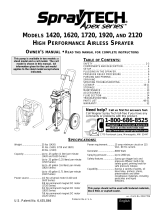
Fluid Section Assembly •
Compartiment liquide • Conjunto de
la sección de fluido (P/N 0294133)
Item
Part # Description Quantity
1 0294319 Packing nut
(torque to 25 ft./lbs.).................1
2 0294377 Upper female adapter...........................1
3 08180 Packings, UHMWPE.............................3
4 00078 Packings, leather ..................................2
5 0294376 Upper male adapter..............................1
6 0294379 Wave spring..........................................1
7 00302 Locknut .................................................1
8 0294318 Cylinder.................................................1
9 13364 Wave spring..........................................1
10 0294316 Piston rod..............................................1
11 0294326 Lower male adapter..............................1
12 08070 Lower packings, UHMWPE ..................3
13 09091 Lower packings, leather........................2
14 0294375 Lower female adapter...........................1
15 13458 Upper ball stop disk..............................1
16 13357 Upper ball cage ....................................1
17 50164 Upper ball .............................................1
18 13359 Upper ball seat .....................................1
19 09446 Washer..................................................1
20 13481 Piston seat retainer
(torque to 250 in./lbs.) ..1
21 13482 Jam nut (torque to 200 in./lbs.) ....................1
22 13381 Upper o-ring..........................................1
23 13380 Lower ball stop disk..............................1
24 51519 Lower ball .............................................1
25 00311 Lower ball cage ....................................1
26 00310 Lower ball seat .....................................1
27 00203 Lower o-ring..........................................1
28 13403 Inlet valve housing (torque to 40 ft./lbs.) .....1
NOTE: Packing kit P/N 0294905 includes those items
marked with a *.
Valve kit P/N 0294689 includes those items
marked with an +.
English
1
11*
18+
14*
21
22*+
23
24*+
25
26+
27*+
28
19*+
20
16
15
17*+
2*
5*
6*
7
8
9*
10
3*
13*
4*
12*
Article Nº de pièce Description Quantité
1 0294319 Écrou de serrage (couple de torsion: 25 pi//lb.)..1
2 0294377 Raccord supérieur femelle....................1
3 08180 Garnitures UHMWPE............................3
4 00078 Garnitures en cuir .................................2
5 0294376 Raccord supérieur mâle .......................1
6 0294379 Ressort ondulé......................................1
7 00302 Contre-écrou.........................................1
8 0294318 Cylindre.................................................1
9 13364 Ressort ondulé......................................1
10 0294316 Tige de piston .......................................1
11 0294326 Raccord inférieur mâle .........................1
12 08070 Garnitures inférieures UHMWPE..........3
13 09091 Garnitures inférieures en cuir ...............2
14 0294375 Raccord inférieur femelle......................1
15 13458 Disque d'arrêt de bille supérieure.........1
16 13357 Logement de bille supérieure ...............1
17 50164 Bille supérieure.....................................1
18 13359 Siège de bille supérieure......................1
19 09446 Rondelle................................................1
20 13481 Fixation de la cale du piston
(couple de torsion:28 Nm (250 in./lbs.))
.............1
21 13482 Contre-écrou
(couple de torsion: 22,5 Nm (200 in./lbs.)).1
22 13381 Joint torique supérieur ..........................1
23 13380 Disque d'arrêt de bille inférieure...........1
24 51519 Bille inférieure.......................................1
25 00311 Logement de bille inférieure .................1
26 00310 Siège de bille inférieure........................1
27 00203 Joint torique inférieur ............................1
28 13403 Logement de la soupage d’aspiration
(couple de torsion: 55 Nm (40 ft./lbs.)) ..............1
Artículo
Pieza # Descripción Cantidad
1 0294319 Tuerca de empaquetadura
(par de torsión hasta de 25 pie./lb)
...................1
2 0294377 Adaptador hembra superior..................1
3 08180 Empaques, UHMWPE ..........................3
4 00078 Empaques, carnaza..............................2
5 0294376 Adaptador macho superior ...................1
6 0294379 Resorte de onda ...................................1
7 00302 Tuerca de seguridad.............................1
8 0294318 Cilindro..................................................1
9 13364 Resorte de onda ...................................1
10 0294316 Varilla del pistón ...................................1
11 0294326 Adaptador macho inferior .....................1
12 08070 Empaques inferiores, UHMWPE ..........3
13 09091 Empaques inferiores, carnaza..............2
14 0294375 Adaptador hembra inferior....................1
15 13458 Disco tope de bola superior..................1
16 13357 Jaula de bola superior ..........................1
17 50164 Bola superior.........................................1
18 13359 Asiento de bola superior.......................1
19 09446 Rondana ...............................................1
20 13481 Retenedor del asiento del pistón
(par de torsión hasta de (250 pulg./lbs.).............1
21 13482 Tuerca de presión
(par de torsión hasta de 200 pulg./lbs.) .............1
22 13381 Aro-sello superior..................................1
23 13380 Disco tope de bola inferior....................1
24 51519 Bola inferior...........................................1
25 00311 Jaula de la bola inferior ........................1
26 00310 Asiento de la bola inferior.....................1
27 00203 Aro-sello inferior....................................1
28 13403 Cámara de la válvula de entrada
(par de torsión hasta de 40 pies/lbs.) ................1
NOTA: El juego de empaquetadura, no. de pieza (P/N)
0294905, incluye los artículos marcados con
asterisco (*).
El juego de la válvula, no. de pieza (P/N) 0294689,
incluye los artículos marcados con un una cruz (+).
Español
NOTA : L'ensemble de remplacement des joints P/N
0294905 contient les articles marqués d'un *.
L'ensemble de remplacement de la valve P/N
0294689 contient les articles marqués d'une +.
Français