HOTPOINT/ARISTON CP87SG1 /HA S User guide
- Category
- Barbecues & grills
- Type
- User guide
This manual is also suitable for
CP 87 SG1/HA S
CP 97 SG1/HA S
English
Operating Instructions
COOKER
Français
Mode d’emploi
CUISINIÈRE
Español
Manual de instrucciones
COCINA
Italiano
Istruzioni per l’uso
CUCINA
Portuges
Instruções para a utilização
FOGÃO
Sommario
Istruzioni per l’uso,1
Avvertenze,2
Assistenza,6
Descrizione dell’apparecchio,8
Descrizione dell’apparecchio,10
Installazione,11
Avvio e utilizzo,14
Precauzioni e consigli,17
Manutenzione e cura,17
Contents
Operating Instructions,1
Warnings,2
Assistance,6
Description of the appliance,8
Description of the appliance,10
Installation,19
Start-up and use,22
Precautions and tips,25
Maintenance and care,25
Sommaire
Mode d’emploi,1
Avertissements,3
Assistance,6
Description de l’appareil,8
Description de l’appareil,10
Installation,27
Mise en marche et utilisation,30
Précautions et conseils,33
Nettoyage et entretien,33
Sumario
Manual de instrucciones,1
Advertencias,3
Asistencia,6
Descripción del aparato,8
Descripción del aparato,10
Instalación,35
Puesta en funcionamiento y uso,38
Precauciones y consejos,41
Mantenimiento y cuidados,41
Índice
Instruções para a utilização,1
Advertências,4
Assistência,7
Descrição do aparelho,9
Descrição do aparelho,10
Instalação,43
Início e utilização,46
Precauções e conselhos,49
Manutenção e cuidados,49
2
Avvertenze
ATTENZIONE: Questo apparecchio e le
sue parti accessibili diventano molto caldi
durante l’uso. Bisogna fare attenzione ed
evitare di toccare gli elementi riscaldanti.
Tenere lontani i bambini inferiori agli 8
anni se non continuamente sorvegliati.
Il presente apparecchio può essere
utilizzato dai bambini a partire dagli 8
anni e da persone con ridotte capacità
siche, sensoriali o mentali oppure con
mancanza di esperienza e di conoscenza
se si trovano sotto adeguata sorveglianza
oppure se sono stati istruiti circa l’uso
dell’apparecchio in modo sicuro e se
si rendono conto dei pericoli correlati.
I bambini non devono giocare con
l’apparecchio. Le operazioni di pulizia
e di manutenzione non devono essere
effettuate dai bambini senza sorveglianza.
ATTENZIONE: Lasciare un fornello
incustodito con grassi e olii può essere
pericoloso e può provocare un incendio.
Non bisogna MAI tentare di spegnere
una amma/incendio con acqua, bensì
bisogna spegnere l’apparecchio e coprire
la amma per esempio con un coperchio
o con una coperta ignifuga.
Non utilizzare prodotti abrasivi né spatole
di metallo taglienti per pulire lo sportello
in vetro del forno in quanto potrebbero
grafare la supercie, provocando, così,
la frantumazione del vetro.
Le superfici interne del cassetto (se
presente) possono diventare calde.
Non utilizzare mai pulitori a vapore o ad alta
pressione per la pulizia dell’apparecchio.
“Eliminare eventuali liquidi presenti sul
coperchio prima di aprirlo.
Non chiudere il coperchio in vetro (se
presente) con i bruciatori gas o la piastra
elettrica ancora caldi.”
ATTENZIONE: Assicurarsi che
l’apparecchio sia spento prima di sostituire
la lampada per evitare la possibilità di
scosse elettriche.
ATTENZIONE: l’uso di protezioni del
piano inappropriate può causare incidenti.
! Quando si inserisce la griglia assicurarsi
che il fermo sia rivolto verso l’alto e nella
parte posteriore della cavità.
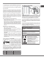
Warnings
WARNING: The appliance and its
accessible parts become hot during use.
Care should be taken to avoid touching
heating elements. Children less than 8
years of age shall be kept away unless
continuously supervised. This appliance
can be used by children aged from 8 years
and above and persons with reduced
physical, sensory or mental capabilities or
lack of experience and knowledge if they
have been given supervision or instruction
concerning use of the appliance in a safe
way and understand the hazards involved.
Children shall not play with the appliance.
Cleaning and user maintenance shall not
be made by children without supervision.
WARNING: Unattended cooking on a hob
with fat or oil can be dangerous and may
result in re.
NEVER try to extinguish a re with water,
but switch off the appliance and then
cover ame e.g. with a lid or a re blanket.
Do not use harsh abrasive cleaners or
sharp metal scrapers to clean the oven
door glass since they can scratch the
Page is loading ...
Page is loading ...
Page is loading ...
Page is loading ...
Page is loading ...
8
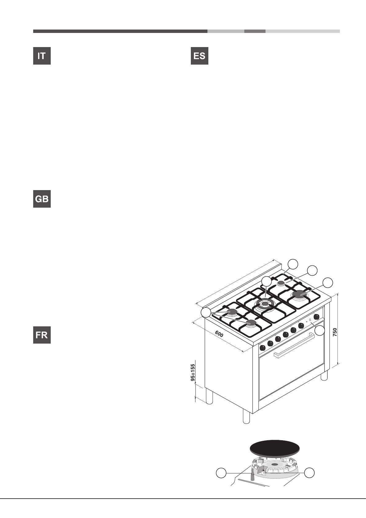
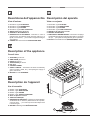
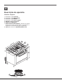
Descrizione dell’apparecchio
Vista d’insieme
1 Bruciatore a gas AUSILIARIO
2 Bruciatore a gas SEMIRAPIDO
3 Bruciatore a gas RAPIDO
4 Bruciatore a gas TRIPLA CORONA
5 GRIGLIA del piano di lavoro
6 PANNELLO DI CONTROLLO
7 DISPOSITIVO DI SICUREZZA - Interviene in caso di
spegnimento accidentale della fiamma (trabocco di
liquidi, correnti d’aria, ...) bloccando l’erogazione del gas
al bruciatore.
8 CANDELA di accensione dei BRUCIATORI GAS
Description of the appliance
Overall view
1 AUXLIARY gas burner
2 SEMI-RAPID gas burner
3 RAPID gas burner
4 TRIPLE RING gas burner
5 Hob grid
6 CONTROL PANEL
7 SAFETY DEVICE - Activates if the ame accidentally
goes out (spills, drafts, etc.), interrupting the supply of
gas to the burner.
8 IGNITOR for Gas BURNERS
Description de l’appareil
Vue d’ensemble
1 Brûleur à gaz AUXILIAIRE
2 Brûleur à gaz SEMI RAPIDE
3 Brûleur à gaz RAPIDE
4 Brûleur à gaz TRIPLE COURONNE
5 Grille du plan de cuisson
6 TABLEAU DE BORD
7 DISPOSITIF DE SÉCURITÉ - Intervient en cas d’extinction
accidentelle de la amme (débordement de liquides,
courants d’air, ...) en interrompant automatiquement
l’arrivée de gaz.
8 BOUGIE d’allumage des BRÛLEURS GAZ
800 - 900
2
4
5
6
1
3
7
8
Descripción del aparato
Vista en conjunto
1 Quemador a gas AUXILIAR
2 Quemador a gas SEMI-RÁPIDO
3 Quemador a gas RÁPIDO
4 Quemador a gas TRIPLE CORONA
5 PARRILLA de placa de cocción
6 PANNEL DE CONTROL
7 DISPOSITIVO DE SEGURIDAD - Interviene si se apaga
accidentalmente la llama (derrame de líquidos, corrientes
de aire, ...) bloqueando la llegada del gas al quemador.
8 BUJÍA de encendido de los QUEMADORES A GAS
Page is loading ...
10
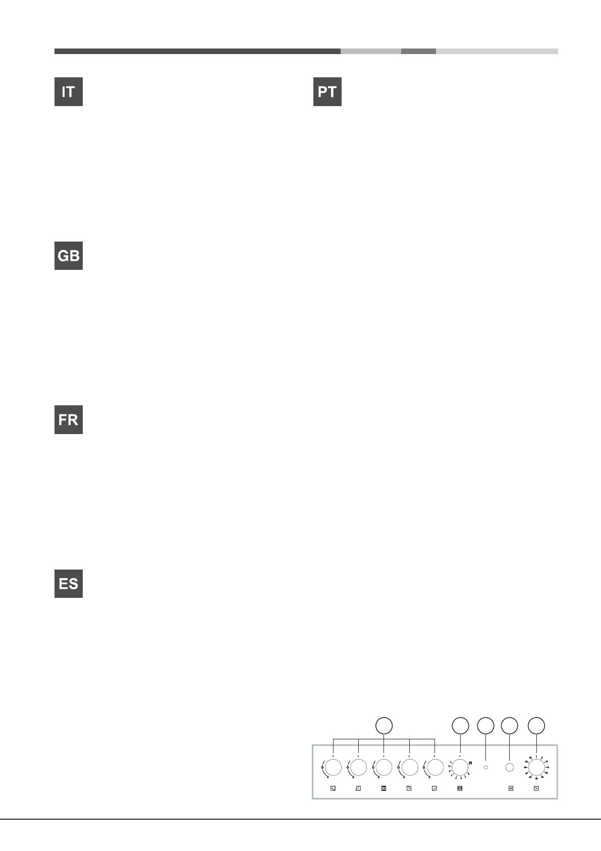
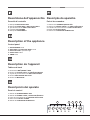
Descrizione dell’apparecchio
Pannello di controllo
1 Manopola BRUCIATORI GAS
2 Manopola FORNO GAS e GRILL ELETTRICO
3 Spia funzionamento GRILL ELETTRICO
4 Pulsante LUCE FORNO
5 Manopola CONTAMINUTI
Description of the appliance
Control panel
1 GAS BURNERS Knob
2 GAS OVEN and ELECTRIC GRILL Knob
3 ELECTRIC GRILL operation light
4 OVEN LIGHT button
5 TIMER Knob
Description de l’appareil
Tableau de bord
1 Boutons des BRÛLEURS À GAZ
2 Bouton du FOUR À GAZ et du GRIL ÉLECTRIQUE
3 Voyant de fonctionnement du GRIL ÉLECTRIQUE
4 Bouton D’ÉCLAIRAGE DU FOUR
5 Bouton du MINUTEUR
Descripción del aparato
Panel de control
1 Mando de QUEMADORES A GAS
2 Mando del HORNO A GAS y ASADOR ELÉCTRICO
3 Piloto de funcionamiento del ASADOR ELÉCTRICO
4 Botón de la LUZ DEL HORNO
5 Mando del CONTADOR DE MINUTOS
Descrição do aparelho
Painel de comandos
1 Selector dos QUEIMADORES A GÁS
2 Selector do FORNO A GÁS e do GRILL ELÉCTRICO
3 Indicador de funcionamento do GRILL ELÉCTRICO
4 Botão da LUZ DO FORNO
5 Selector do CONTADOR DE MINUTOS
1 2 3 4 5
Page is loading ...
Page is loading ...
Page is loading ...
Page is loading ...
Page is loading ...
Page is loading ...
Page is loading ...
Page is loading ...
GB
19
Installation
! Before placing your new appliance into operation please
read these operating instructions carefully. It contains
important information concerning the safe installation and
operation of the appliance.
! Please keep these operating instructions for future
reference. Make sure that the instructions are kept with the
appliance if it is sold, given away or moved.
! The appliance must be installed by a qualied professional
in accordance with the instructions provided.
! Any necessary adjustment or maintenance must be
performed after the cooker has been disconnected from
the electricity supply.
The cookers have the following technical specications:
Category: II 2H3+
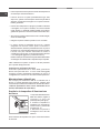
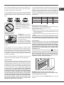
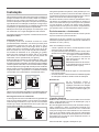
Room ventilation
The appliance may only be installed in permanently-
ventilated rooms, according to current national legislation.
The room in which the appliance is installed must be
ventilated adequately in order to provide as much air as is
needed by the normal gas combustion process (the ow of
air must not be lower than 2 m
3
/h per kW of installed power).
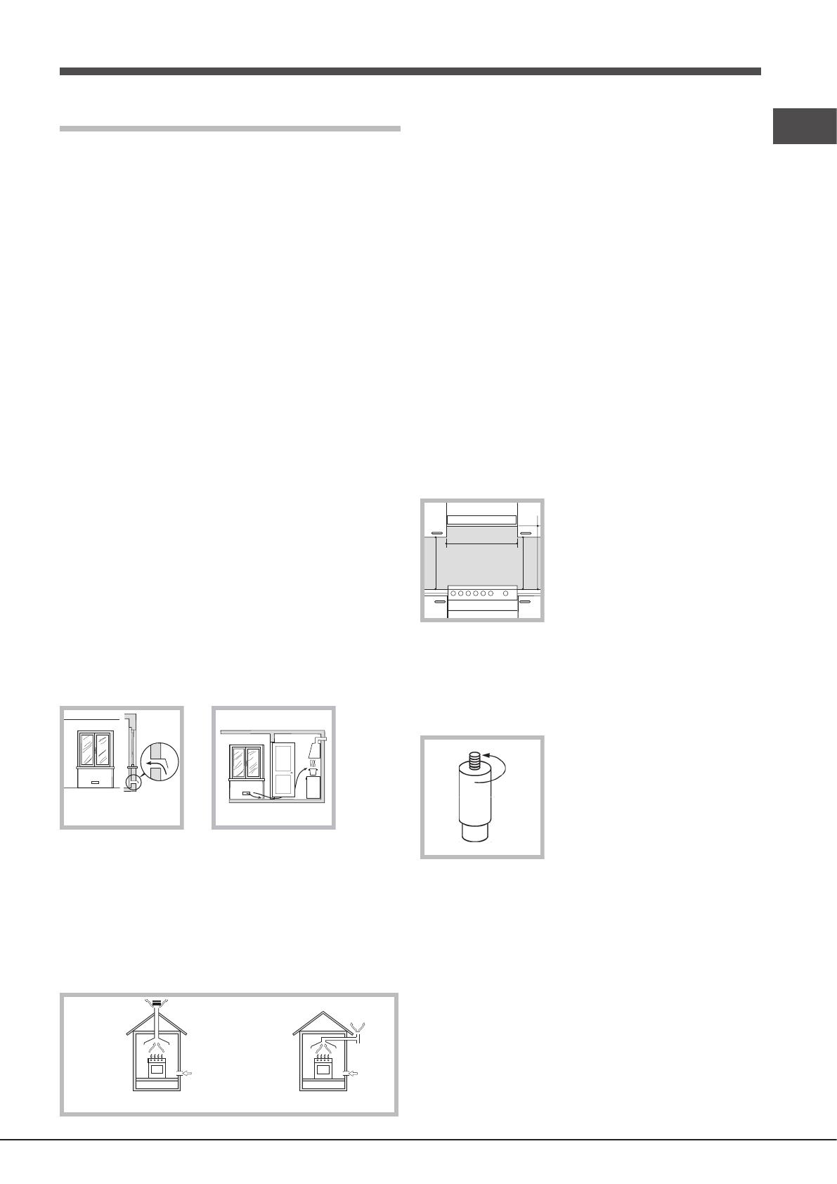
The air inlets, protected by grilles, should have a duct
with an inner cross section of at least 100 cm
2
and should
be positioned so that they are not liable to even partial
obstruction (see gure A).
These inlets should be enlarged by 100% - with a minimum of
200 cm
2
- whenever the surface of the hob is not equipped with
a ame failure safety device. When the ow of air is provided in
an indirect manner from adjacent rooms (see gure B), provided
that these are not communal parts of a building, areas with
increased re hazards or bedrooms, the inlets should be tted
with a ventilation duct leading outside as described above.
A
Examples of
ventilation holes
for comburant air.
Enlarging the ventilation slot
between window and floor.
Adjacent
Room
Room to be
Vented
A B
! After prolonged use of the appliance, it is advisable to open
a window or increase the speed of any fans used.
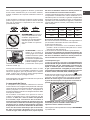
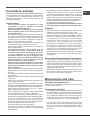
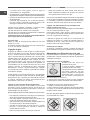
Disposing of combustion fumes
The efcient disposal of combustion fumes should be
guaranteed using a hood which is connected to a safe
and efcient natural suction chimney, or using an electric
fan which begins to operate automatically every time the
appliance is switched on (see gure).
In a chimney stack or branched flue.
(exclusively for cooking appliances)
Directly to
the Outside
! The liqueed petroleum gases are heavier than air and
collect by the oor, therefore all rooms containing LPG
cylinders must have openings leading outside so that any
leaked gas can escape easily.
LPG cylinders, therefore, whether partially or completely full,
must not be installed or stored in rooms or storage areas which
are below ground level (cellars, etc.). Only the cylinder being
used should be stored in the room; this should also be kept well
away from sources of heat (ovens, chimneys, stoves) which
may cause the temperature of the cylinder to rise above 50°C.
Positioning and levelling
! The appliance may be installed alongside any cupboards
whose height does not exceed that of the hob surface.
! Make sure that the wall in contact with the back of the appliance
is made from a non-ammable, heat-resistant material (T 90°C).
To install the appliance correctly:
• Place it in the kitchen, the dining room or the studio at
(not in the bathroom).
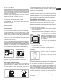
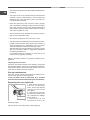
• If the top of the hob is higher than the cupboards, the
appliance must be installed at least 500 mm away from
them.
HOOD
420
Min.
min. 650 mm. with hood
min.
700 mm. without hood
mm.
600
Min. mm.
420
Min. mm.
• If the cooker is installed
underneath a wall cabinet, there
must be a minimum distance of 420
mm between this cabinet and the
top of the hob.
This distance should be increased
to 700 mm if the wall cabinets are
ammable (see gure).
• Do not position blinds behind the cooker or less than 200
mm away from its sides.
• Any hoods must be installed in accordance with the
instructions listed in the relevant operating manual.
Levelling
If it is necessary to level the
appliance, screw the adjustable
feet into the places provided on
each corner of the base of the
cooker (see gure).
Electrical connection
Install a standardised plug corresponding to the load indicated
on the appliance data plate (see Technical data table).
The appliance must be directly connected to the mains using
an omnipolar switch with a minimum contact opening of 3
mm installed between the appliance and the mains. The
switch must be suitable for the charge indicated and must
comply with current electrical regulations (the earthing wire
must not be interrupted by the switch). The supply cable
must be positioned so that it does not come into contact
with temperatures higher than 50°C at any point.
Before connecting the appliance to the power supply, make
sure that:
20
GB
• The appliance is earthed and the plug is compliant with
the law.
• The socket can withstand the maximum power of the
appliance, which is indicated by the data plate.
• The voltage is in the range between the values indicated
on the data plate.
• The socket is compatible with the plug of the appliance.
If the socket is incompatible with the plug, ask an
authorised technician to replace it. Do not use extension
cords or multiple sockets.
! Once the appliance has been installed, the power supply
cable and the electrical socket must be easily accessible.
! The cable must not be bent or compressed.
! The cable must be checked regularly and replaced by
authorised technicians only.
! The manufacturer declines any liability should these
safety measures not be observed.
Replacing the cable
Use a rubber cable of the type H05VV-F with a cross section
of 3 x 1 mm².
The yellow-green earth wire must be 2 ÷ 3 cm longer than
the other wires.
Gas connection
Connection to the gas network or to the gas cylinder
may be carried out using a exible rubber or steel hose,
in accordance with current national legislation and after
making sure that the appliance is suited to the type of gas
with which it will be supplied (see the rating sticker on the
cover: if this is not the case see below). When using liquid
gas from a cylinder, install a pressure regulator which
complies with current national regulations.
! Make sure that the gas supply pressure is consistent
with the values indicated in the Table of burner and nozzle
specifications (see below). This will ensure the safe
operation and durability of your appliance while maintaining
efcient energy consumption.
Gas connection using a exible rubber hose
Make sure that the hose complies with current national
legislation. The internal diameter of the hose must measure: 8
mm for a liquid gas supply;13 mm for a methane gas supply.
Once the connection has been performed, make sure that
the hose:
• Does not come into contact with any parts which reach
temperatures of over 50°C.
• Is not subject to any pulling or twisting forces and that it
is not kinked or bent.
• Does not come into contact with blades, sharp corners
or moving parts and that it is not compressed.
• Is easy to inspect along its whole length so that its
condition may be checked.
• Is shorter than 1500 mm.
• Fits rmly into place at both ends, where it will be xed
using clamps which comply with current regulations.
! If one or more of these conditions is not fullled or if the cooker
must be installed according to the conditions listed for class
2 - subclass 1 appliances (installed between two cupboards),
the exible steel hose must be used instead (see below).
Connecting a exible jointless stainless steel pipe to
a threaded attachment
Make sure that the hose and gaskets comply with current
national legislation.
To begin using the hose, remove the hose holder on
the appliance (the gas supply inlet on the appliance is a
cylindrical threaded 1/2 gas male attachment).
! Perform the connection in such a way that the hose length
does not exceed a maximum of 2 metres, making sure that
the hose is not compressed and does not come into contact
with moving parts.
Checking the connection for leaks
When the installation process is complete, check the hose
ttings for leaks using a soapy solution. Never use a ame.
Adapting to different types of gas
It is possible to adapt the appliance to a type of gas other
than the default type (this is indicated on the rating label
on the cover).
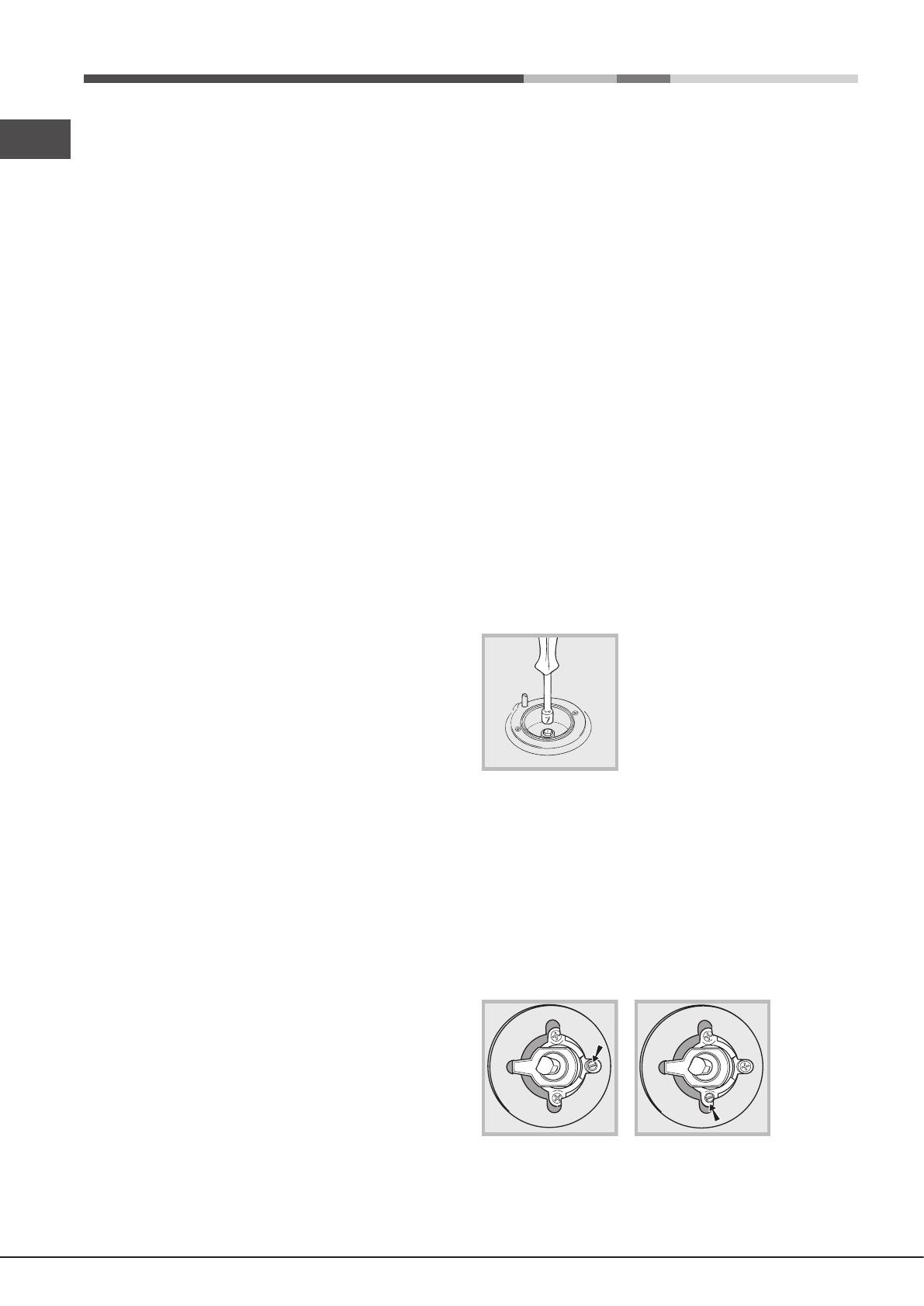
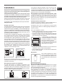
Adapting the hob
Replacing the nozzles for the hob
burners:
1. Remove the hob grids and slide
the burners off their seats.
2. Unscrew the nozzles using a 7
mm socket spanner (see gure), and
replace them with nozzles suited to
the new type of gas (see Burner and
nozzle specications table).
3. Replace all the components by following the above
instructions in reverse.
Adjusting the hob burners’ minimum setting:
1. Turn the tap to the minimum position.
2. Remove the knob and adjust the regulatory screw, which
is positioned inside or next to the tap pin, until the ame is
small but steady.
! If the appliance is connected to a liquid gas supply, the
regulatory screw must be fastened as tightly as possible.
3. While the burner is alight, quickly change the position of
the knob from minimum to maximum and vice versa several
times, checking that the ame is not extinguished.
GB
21
! The hob burners do not require primary air adjustment.
! After adjusting the appliance so it may be used with a
different type of gas, replace the old rating label with a new
one which corresponds to the new type of gas (these labels
are available from Authorised Technical Assistance Centres).
! Should the gas pressure used be different (or vary slightly)
from the recommended pressure, a suitable pressure regulator
must be tted to the inlet hose in accordance with current
national regulations relating to “regulators for channelled gas”.
Gas oven :
• Open the oven door (to reach the oven burner, remove
the oor);
• loosen the 2 screws which hold the oven burner in place,
remove the burner and replace the nozzles “N” with
suitable ones for the new type of gas according to the
table “Burner and nozzle characteristics”.
• re-assemble all the components, regulate the air in the
burner as well as the minimum ow of the tap.
Adjusting the low ame
• Open the door and remove the oven oor;
• put the oven knob to position maximum and light the burner;
• close the door and wait for about 15 minutes;
• put the knob to position 1 (minimum);
• remove the actual knob and regulate the adjusting screw
situated above the thermostat spindle;
• after regulating the low ame as required, with the burner
lit, change from the high to the low ame position abruptly
for a few times and close the oven door normally, making
sure that the burner does not go out.
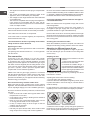
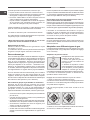
Primary air ow control
NP
R
The oven burners and grill are tted
with the primary air control bushing
“R” (gas oven burners). The primary
air ow is controlled in an appropriate
way when the ame is stable and
even, without killing the ame when
the burner is cold or lighting the
nozzle when the burner is hot.
The flow may be adjusted by
loosening the screw “P” and moving the bushing “R” so
that the opening “X” corresponds to the values in the table
below. Once all the adjustments have been made, fasten
the bushing “R” with the screw “P”.
Burner
Opening "X" (mm)
natural gas "G20"
Opening "X" (mm)
liquid gas "G30-G31"
Oven
G
rill
6.5
5
16
12
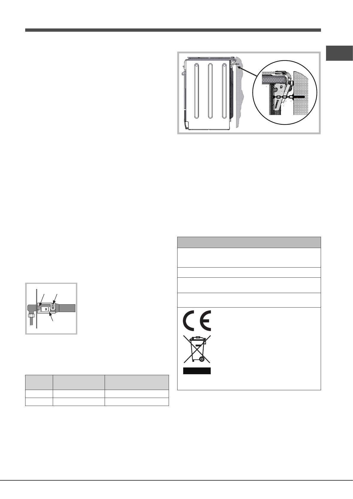
Safety Chain
! In order to prevent the appliance from overturning
accidentally, for example in case of a child climbing
onto the oven door, the safety chains MUST be installed!
The cooker is provided with safety chains that must be
xed with a screw (not supplied as accessory) on the wall
behind the appliance, at the same height as the xing point
on the appliance.
Make sure that the chains are xed in the back of the
cooker, as shown in the drawing, in such way to be tight
and parallel to the oor.
! When the installation process is complete, the chains must
be kept in tension!
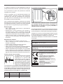
TABLE OF CHARACTERISTICS
Oven
dimensions
HxLxP
33 x 54 x 38 cm
Volume
lt. 68
Voltage and
frequency
see data plate
Burners
may be adapted for use with any type
of gas shown on the data plate.
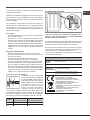
This appliance conforms to the following
European Economic Community
directives:
- 2006/95/EEC dated 12/12/06 (Low
Voltage) and subsequent amendments
- 2004/108/EEC dated 15/12/04
(Electromagnetic Compatibility) and
subsequent amendments
- 93/68/EEC dated 22/07/93 and
subsequent amendments.
- 2009/142/EEC dated 30/11/09 (Gas)
and subsequent amendments.
- 2012/19/EEC and subsequent
amendments.
22
GB
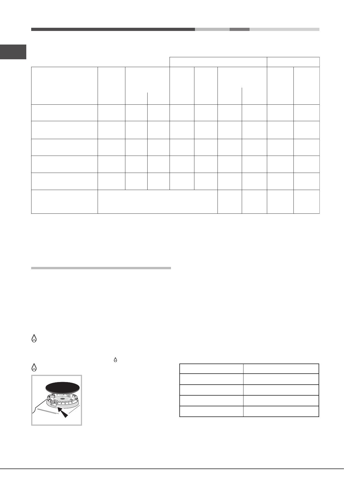
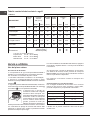
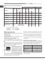
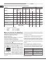
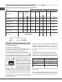
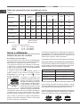
Table of burner and nozzle specications
Table 1 Liquid gas Natural gas
BURNER
Diameter
(mm)
Heating
power
kW (H.s.*)
By-pass
1/100
(mm)
Nozzle
1/100
Nozzle
1/100
(mm)
Flow *
g/h
Flow *
l/h
(mm)Nomin. Red. G30 G31 G20
.3 Rapid
0100 3.00 0.7 40 86 218 214 116 286
.2 Semi-rapid
575 1.65 0.4 30 64 120 118 96 157
.1 Auxiliary
55 1.00 0.4 30 50 73 71 71 95
.4 Triple Ring 130 3.25 1.3 57 91 236 232 124 309
Gas oven 4.00 0.8 45 95 291 286 142 381
Supply pressure
Nominal (mbar)
Minimal (mbar)
Maximised (mbar)
28-30
20
35
37
25
45
20
17
25
* At 15°C and 1013 mbar - dry gas
Propane G31 P.C.S. = 50.37 MJ/Kg
Butane G30 P.C.S. = 49.47 MJ/Kg
Methane G20 P.C.S. = 37.78 MJ/m
3
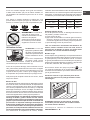
Start-up and use
Using the hob
Lighting the burners
For each BURNER knob there is a complete ring showing
the strength of the ame for the relevant burner.
To light one of the burners on the hob:
1. Bring a ame or gas lighter close to the burner.
2. Press the BURNER knob and turn it in an anticlockwise
direction so that it is pointing to the maximum ame setting
.
3. Adjust the intensity of the ame to the desired level by
turning the BURNER knob in an anticlockwise direction.
This may be the minimum setting , the maximum setting
or any position in between the two.
The appliance is fitted with an
electronic lighting device which is
integrated into the knob. Simply light
the desired burner by turning the
corresponding knob in an anti-
clockwise direction, until it is aligned
with the large ame symbol, press
it all the way in to activate the
electronic ignition and hold it in that
position until the burner is lit. The burner might be extinguished
when the knob is released. If this occurs, repeat the process,
holding the knob down for a longer period of time.
! If the ame is accidentally extinguished, switch off the burner
and wait for at least 1 minute before attempting to relight it.
If the appliance is equipped with a ame failure safety device*,
press and hold the BURNER knob for approximately 2-3
seconds to keep the ame alight and to activate the device.
To switch the burner off, turn the knob until it reaches the
stop position ●.
Practical advice on using the burners
For the burners to work in the most efcient way possible and
to save on the amount of gas consumed, it is recommended
that only pans which have a lid and a at base are used.
They should also be suited to the size of the burner.
Burner
Fast (R)
Semi Fast (S)
Auxiliary (A)
Triple Crown (TC)
Ø Cookware Diameter (cm)
24 - 26
16 - 22
10 - 14
24 - 26
! Make sure the pans do not overlap the edges of the hob
while it is being used.

GB
23
! For models equipped with a reducer grid, the latter must
be used only for the auxiliary burner, when pans with a
diameter of less than 12 cm are used.
For the best performance of your burners, keep the following
in mind: All types of pans can be used on the burners. The
important thing is that the bottom should be completely
even.
WARNING! The glass lid can
break in if it is heated up. Turn
off all the burners and the electric
plates before closing the lid.
Applies to the models with glass
cover only.
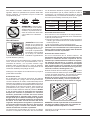
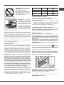
Using the oven
WARNING ! The oven is
provided with a stop system
to extract the racks and
prevent them from coming
out of the oven (1).
As shown in the drawing,
to extract them completely,
simply lift the racks, holding
them on the front part, and
pull (2).
! The rst time you use your appliance, heat the empty
oven with its door closed at its maximum temperature for
at least half an hour. Ensure that the room is well ventilated
before switching the oven off and opening the oven door.
The appliance may emit a slightly unpleasant odour caused
by protective substances used during the manufacturing
process burning away.
! Never put objects directly on the bottom of the oven; this
will prevent the enamel coating from being damaged.
The oven knob
This is the device which is used to select the various oven
functions and the most suitable cooking temperature for the
foods (temperatures between 150°C and 275°C are also
indicated on the knob). The electronic oven ignition device
is built into the control knob. To light the burner, press the
knob in fully and turn it in an anticlockwise direction until
it reaches position 8. Given that the oven is tted with
a safety device, after the burner has been lit the oven
knob should be held in that position for approximately
6 seconds, in order to allow the gas to pass through
until the safety thermocouple heats up. The electronic
oven burner ignition device should not be activated for
more than 15 seconds. If after 15 seconds the burner
has not been ignited, release the oven knob, open
the oven door and wait for at least one minute before
attempting to ignite the burner again.
The cooking temperature is selected by aligning the value
indication with the reference mark on the control panel; the
complete range of temperatures which are available for
selection is displayed below. The oven will automatically
reach the set temperature, which is kept constant by the
corresponding monitoring device (the thermostat) controlled
by the knob.
Position 1 (minimum)
150° - 155°C
Position 5
215°C
Position 2
155°C
Position 6
235°C
Position 3
175°C
Position 7
260°C
Position 4
195°C
Position 8
275°C
Switching the oven on manually
In the event of a momentary lapse in the electricity supply,
the oven burner may be ignited manually:
a) Open the oven door.
b) Bring a match or lighter close to the opening, press the
oven knob and turn it in an anticlockwise direction until
it reaches position 8.
c) When the burner has been lit successfully, close the oven
door.
! If the burner ame is accidentally extinguished, shut off
the oven knob, open the oven door and wait for at least
one minute before attempting to light the burner again.
The grill knob
Your oven is tted with an electric grill. The extremely high
and direct temperature of the grill makes it possible to
brown the surface of meats and roasts while locking in
the juices to keep them tender. The grill is also highly
recommended for dishes that require a high surface
temperature: such as beef steaks, veal, rib steak, llets,
hamburgers etc...
By turning the oven knob until it reaches the position, the
rotisserie spit motor is activated as well as the infrared grill.
This motor will remain active as long as the grill is operating.
When cooking with the grill, we recommend that you
keep the oven door open and that you apply the knob
protection shield as indicated in gure.
WARNING: when the grill is in operation, the
surrounding parts can become very hot. Please keep
children away from the cooker.
Stop cooking by turning the SELECTOR knob to the “0”
position.
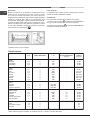
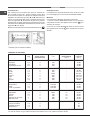
24
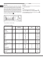
GB
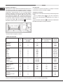
Food to be cooked
Pasta
Lasagne
Cannelloni
Pasta bakes
Meat
Veal
Chicken
Turkey
Duck
Rabbit
Pork
Lamb
Fish
Mackerel
Dentex
Trout baked in paper
Pizza and Cake
Neapolitan
Biscuits
Tarts
Chocolate cake
Raised Cakes
Grill cooking
Toasted sandwiches
Pork chops
Mackerel
Wt.
(Kg)
2,5
2,5
2,5
1,7
1,5
3,0
1,8
2
2,1
1,8
1,1
1,5
1,0
1,0
0,5
1,1
1
1
n°4
1,5
1,1
Cooking position
of shelves
from bottom
3
3
3
3
3
3
3
3
3
3
3
3
3
3
3
3
3
3
4
4
4
Temperature
(°C)
210
210
210
230
220
MAX
230
230
230
230
210-230
210-230
210-230
MAX
180
180
200
200
Pre-heating
time
(min.)
-
-
-
-
-
-
-
-
-
-
-
-
-
15
15
15
15
15
Cooking
time
(min.)
75-80
75-80
75-80
85-90
110-115
95-100
120-125
105-110
100-110
90-95
55-60
60-65
40-45
30-35
30-35
30-35
45-50
50-55
10
30
35
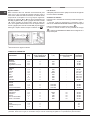
NB: cooking times are approximate and may vary according to personal taste.
When cooking using the grill, the dripping pan must always be placed on the 1st oven rack from the bottom
Cooking advice table
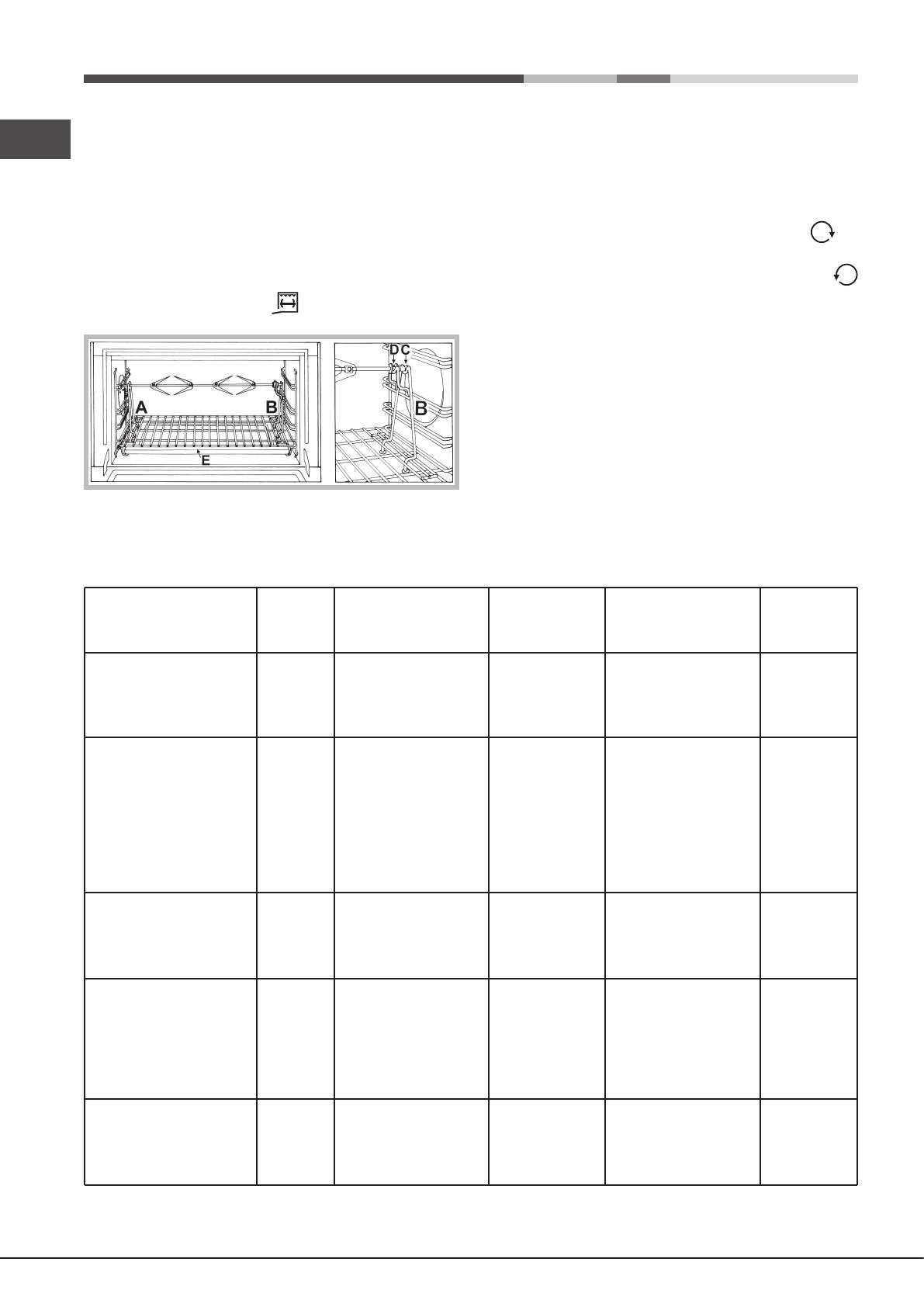
Spit roast *
This accessory should only be used when cooking with
the grill. Proceed as follows: thread the meat you wish to
cook onto the rod positioned across the oven lengthwise,
xing it in place with the adjustable forks supplied. Position
supports “A” and “B” in the relevant holes in dripping pan
“E”, rest the groove on the rod in slot “C” and use the guide
rail to place the rack in the lowest position in the oven; next
position the rod in the rotisserie spit hole, sliding the groove
forwards to slot “D” (see gures). Start the rotisserie using
the knob set to cooking mod ;
* Only available on certain models.
Oven light
The light may be switched on at any moment by pressing
the OVEN LIGHT button.
Timer
To activate the Timer proceed as follows:
1. Turn the TIMER knob in a clockwise direction for
almost one complete revolution to set the buzzer.
2. Turn the TIMER knob in an anticlockwise direction
to set the desired length of time.

GB
25
Precautions and tips
! This appliance has been designed and manufactured
in compliance with international safety standards. The
following warnings are provided for safety reasons and
must be read carefully.
General safety
• The instruction booklet accompanies a class
1(insulated) or class 2 - subclass 1 (recessed
between2 cupboards) appliance.
• These instructions are only valid for the countries
whose symbols appear in the manual and on the
serial number plate.
• The appliance was designed for domestic use inside the
home and is not intended for commercial or industrial use.
• The appliance must not be installed outdoors, even in
covered areas. It is extremely dangerous to leave the
appliance exposed to rain and storms.
• When moving or positioning the appliance, always use
the handles provided on the sides of the oven.
• Do not touch the appliance while barefoot or with wet or
damp hands and feet.
• The appliance must be used by adults only for
the preparation of food, in accordance with the
instructions provided in this booklet. Any other
use of the appliance (e.g. for heating the room)
constitutes improper use and is dangerous. The
manufacturer may not be held responsible for any
damage caused as a result of improper, incorrect
and unreasonable use of the appliance.
• Do not touch the heating elements or certain parts
of the oven door when the appliance is in use; these
parts become extremely hot. Keep children well away
from the appliance.
• Make sure that the power supply cables of other electrical
appliances do not come into contact with the hot parts of
the oven.
• The ventilation and heat dispersal openings must never
be obstructed.
• Always grip the oven door handle in the centre: the ends
may be hot.
• Always use oven gloves when placing cookware in the
oven or when removing it.
• Do not use aluminium foil to line the bottom of the oven.
• Do not place ammable materials in the oven: if the appliance
is switched on accidentally, the materials could catch re.
• Always make sure the knobs are in the “●”/“○” position
when the appliance is not in use.
• When unplugging the appliance, always pull the plug
from the mains socket; do not pull on the cable.
• Do not perform any cleaning or maintenance work without
having disconnected the appliance from the electricity mains.
• If the event of malfunctions, under no circumstances
should you attempt to perform the repairs yourself.
Contact an authorised Service Centre (see Assistance).
• Do not rest objects on the open oven door.
• Do not let children play with the appliance.
• If the cooker is placed on a pedestal, take the necessary
precautions to prevent the cooker from sliding off the
pedestal itself.
• The appliance should not be operated by people (including
children) with reduced physical, sensory or mental
capacities, by inexperienced individuals or by anyone
who is not familiar with the product. These individuals
should, at the very least, be supervised by someone who
assumes responsibility for their safety or receive preliminary
instructions relating to the operation of the appliance.
• Do not let children play with the appliance.
• The appliance is not intended to be operated by means
of an external timer or separate remote-control system.
Disposal
• When disposing of packaging material: observe local
legislation so that the packaging may be reused.
• The European Directive 2012/19/EEC on Waste
Electrical and Electronic Equipment (WEEE), requires
that old household electrical appliances must not
be disposed of in the normal unsorted municipal
waste stream. Old appliances must be collected
separately in order to optimise the recovery and
recycling of the materials they contain and reduce
the impact on human health and the environment.
The crossed out “wheeled bin” symbol on the product
reminds you of your obligation, that when you dispose
of the appliance it must be separately collected.
Consumers should contact their local authority or retailer
for information concerning the correct disposal of their
old appliance.
Respecting and conserving the environment
• You can help to reduce the peak load of the electricity
supply network companies by using the oven in the hours
between late afternoon and the early hours of the morning.
• Always keep the oven door closed when using the GRILL
modes: This will achieve improved results while saving
energy (approximately 10%).
• Regularly check the door seals and wipe clean to ensure
they are free of debris so that they stick properly to the
door and do not allow heat to disperse.
Maintenance and care
Switching the appliance off
Disconnect your appliance from the electricity supply before
carrying out any work on it.
Cleaning the appliance
• The stainless steel or enamel-coated external parts and
the rubber seals may be cleaned using a sponge which
has been soaked in lukewarm water and neutral soap.
Use specialised products for the removal of stubborn
stains. After cleaning, rinse well and dry thoroughly. Do
not use abrasive powders or corrosive substances.
• The hob grids, burner caps, ame spreader rings and
burners may be removed to make cleaning easier; wash
them in hot water and non-abrasive detergent, making
sure all burnt-on residue is removed before drying them
thoroughly.

26
GB
• Clean the terminal part of the ame failure safety devices*
frequently.
• The inside of the oven should ideally be cleaned after
each use, while it is still lukewarm. Use hot water and
detergent, then rinse well and dry with a soft cloth. Do
not use abrasive products.
• Clean the glass part of the oven door using a sponge
and a non-abrasive cleaning product, then dry thoroughly
with a soft cloth. Do not use rough abrasive material or
sharp metal scrapers as these could scratch the surface
and cause the glass to crack.
• The accessories can be washed like everyday crockery,
and are even dishwasher safe.
• Only clean the appliance when the oven is cold.
• The steel parts and especially the areas with the screen-
printed symbols should not be cleaned with solvents or
abrasive detergents. It is advisable to use only a damp
cloth with lukewarm water and washing up liquid.
Stainless steel may remain stained if in long-term contact
with very calcareous water or aggressive detergents
(containing phosphorus).
It is therefore always necessary to rinse and dry all
surfaces thoroughly after cleaning.
! Never use steam cleaners or pressure cleaners on the
appliance.
Inspecting the oven seals
Check the door seals around the oven regularly. If the seals
are damaged, please contact your nearest Authorised After-
sales Service Centre. We recommend that the oven is not
used until the seals have been replaced.
Gas tap maintenance
Over time, the tap may become jammed or difcult to turn.
If this occurs, the tap must be replaced.
! This procedure must be performed by a qualied
technician who has been authorised by the manufacturer.
Replacing the oven light bulb
1. After disconnecting the
oven from the electricity
mains, remove the glass lid
covering the lamp socket
(see gure).
2. Unscrew the light bulb
and replace it with a similar
one: voltage 230 V, wattage
25 W, cap E 14.
3. Replace the lid and
reconnect the oven to the
electricity supply.
! Do not use the oven lamp as/for ambient lighting.
Page is loading ...
Page is loading ...
Page is loading ...
Page is loading ...
Page is loading ...
Page is loading ...
Page is loading ...
Page is loading ...
Page is loading ...
Page is loading ...
Page is loading ...
Page is loading ...
Page is loading ...
Page is loading ...
Page is loading ...
Page is loading ...
Page is loading ...
Page is loading ...
Page is loading ...
Page is loading ...
Page is loading ...
Page is loading ...
Page is loading ...
Page is loading ...
Page is loading ...
Page is loading ...
-
 1
1
-
 2
2
-
 3
3
-
 4
4
-
 5
5
-
 6
6
-
 7
7
-
 8
8
-
 9
9
-
 10
10
-
 11
11
-
 12
12
-
 13
13
-
 14
14
-
 15
15
-
 16
16
-
 17
17
-
 18
18
-
 19
19
-
 20
20
-
 21
21
-
 22
22
-
 23
23
-
 24
24
-
 25
25
-
 26
26
-
 27
27
-
 28
28
-
 29
29
-
 30
30
-
 31
31
-
 32
32
-
 33
33
-
 34
34
-
 35
35
-
 36
36
-
 37
37
-
 38
38
-
 39
39
-
 40
40
-
 41
41
-
 42
42
-
 43
43
-
 44
44
-
 45
45
-
 46
46
-
 47
47
-
 48
48
-
 49
49
-
 50
50
-
 51
51
-
 52
52


HOTPOINT/ARISTON CP87SG1 /HA S User guide
- Category
- Barbecues & grills
- Type
- User guide
- This manual is also suitable for
Ask a question and I''ll find the answer in the document
Finding information in a document is now easier with AI
in other languages
Related papers
-
HOTPOINT/ARISTON CP77SG1 /HA S User guide
-
Whirlpool CP98SEA /HA S Operating instructions
-
-
-
Hotpoint Ariston CP77SP2 /HA S User guide
-
-
-
-
Whirlpool PK 640 R AX /HA User guide
-
Other documents
-
Indesit CP 058 MT.2 S Owner's manual
-
-
-
-
-
-
Scholtes CI 66 M A Operating Instructions Manual
-
-
-