Page is loading ...

Owner's Manual/Manual Del Propietario
CRI FTSMFIN°
1/2 HP
GARAGE DOOR OPENER
ABRIDOR DE PUERTA DE COCHERA
For Residential Use Only/Solo para uso residencial
DE
Model/Modelo 139.53902D
m
Z
G3
I11
"13
Z_
O
Read and follow all safety rules and
operating instructions before first use
of this product.
Fasten the manual near the garage
door after installation.
Periodic checks of the opener are
required to ensure safe operation.
Leer y seguir todas las reglas de
seguridad y las instrucciones de
operacion antes de usar este producto
por primera vez.
Guardar este manual cerca de la
puerta de la cochera.
Se deben realizar revisiones
periodicas del abridor de puertas para
asegurar su operacion segura.
0Qus
Sears, Roebuck and Co., Hoffman Estates, IL 60179 U.S.A
www.sears.com/craftsman

TABLE OF CONTENTS
INTRODUCTION 2- 7
Safetysymbol and signal word review.......................................2
Preparing your garagedoor........................................................ 3
Tools needed..............................................................................3
Planning ..................................................................................4-5
Carton inventory .........................................................................6
Hardware inventory.....................................................................7
ASSEMBLY 8-11
Assemblethe rail.....................................................................8-9
Fastenthe railto the motor unit and install the trolley .............10
Attach the rail brackets.............................................................11
INSTALLATION 11-26
Installation safety instructions ..................................................11
Determinethe headerbracket location .....................................12
Install the headerbracket..........................................................13
Attach the rail to the headerbracket.........................................14
Install the Protector System_...............................................15-17
Position the opener...................................................................18
Hangthe opener .......................................................................19
Install the door control .............................................................20
Electrical requirements.............................................................21
Completesafety reversing sensor installation...........................21
Install the lights .......................................................................22
Attach the emergencyreleaserope and handle........................ 22
Fastenthe door bracket.......................................................23-24
Connectthe door arm to thetrolley .....................................25-26
ADJUSTMENT 27-29
Adjust thetravel limits .............................................................. 27
Adjust theforce ........................................................................ 28
Testthe safety reversalsystem.................................................29
Testthe Protector System®.......................................................29
OPERATION 30-34
Operationsafety instructions .................................................... 30
Using your garagedoor opener................................................30
Using the wall-mounted door control .......................................31
To open the door manually.......................................................31
Careofyour opener..................................................................32
Having a problem?....................................................................33
Diagnostic chart........................................................................ 34
PROGRAMMING 35-36
To add or reprograma hand-held remote control .................... 35
To eraseall codes from motor unit memory............................ 35
3-Function remote controls ......................................................35
To add, reprogram or changea KeylessEntry PIN...................36
REPAIRPARTS 37-38
Rail assembly parts ..................................................................37
Installation parts .......................................................................37
Motor unit assembly parts........................................................ 38
ACCESSORIES 39
WARRANTY 39
INTRODUCTION
Safely Symboland SignalWordReview
This garage door opener has beendesignedand tested to offer safe serviceprovided it is installed, operated,maintainedand tested in
strict accordancewith the instructions and warnings contained in this manual.
Mechanical
Electrical
Whenyou seethese SafetySymbols and Signal Words on the
following pages,they will alertyou to the possibility of serious
injury or deathif you do not comply with the warnings that
accompanythem. Thehazardmay come from something
mechanicalor from electric shock. Readthe warnings carefully.
Whenyou seethis Signal Word on the following pages, it will
alertyou to the possibility of damageto your garagedoor and/or
the garagedoor opener if you do not comply with the cautionary
statements that accompany it. Readthem carefully.

Preparing your garage door
Beforeyou begin:
• Disablelocks.
• Removeany ropes connectedto garage door.
• Completethe following test to make sureyour garage
door is balancedand is not sticking or binding:
1. Lift the door about halfwayas shown. Releasethe door. If
balanced, it should stay in place,supported entirely by its
springs.
2. Raiseand lower the door to seeif there is any binding or
sticking.
If your door binds, sticks, or is out of balance,call atrained door
systems technician.
To prevent possible SERIOUSINJURYor DEATH:
• ALWAYScall atrained door systems technician if garage
door binds, sticks, or is out of balance.An unbalanced
garagedoor may NOTreversewhen required.
• NEVERtry to loosen, move or adjust garagedoor, door
springs, cables,pulleys, brackets or their hardware,ALL of
which are under EXTREMEtension.
• DisableALL locks and removeALL ropes connectedto
garagedoor BEFOREinstalling and operating garagedoor
opener to avoidentanglement.
To prevent damageto garage door and opener:
• ALWAYSdisable locks BEFOREinstalling and operatingthe
opener.
• ONLYoperate garagedoor opener at 120V, 60 Hzto avoid
malfunction and damage.
SectionaJDoor
One-Piece Door
Too/s needed
During assembly, installation and adjustment of the opener,
instructions will call for handtools as illustrated below.
Level(Optional)
Tape Measure
Pencil
Wire Cutters
Hack Saw
Stepladder
Drill
3/16", 5/16" and
5/32" Drill Bits
Screwdriver
Claw Hammer
Adjustable EndWrench

P_nnmg
Identify the type and height of your garagedoor. Surveyyour
garageareato see if any of the conditions below apply to your
installation. Additional materials may be required.You may find it
helpful to referback to this pageand the accompanying
illustrations asyou proceedwith the installation of your opener.
Dependingon your requirements,there are several installation
steps which may call for materialsor hardware not included in
the carton.
• Installation Step 1 - Lookat the wall or ceiling abovethe
garagedoor. Theheader bracketmust be securelyfastenedto
structural supports.
• Installation Step4 - Dependingupon garageconstruction,
extension brackets or wood blocks may be neededto install
sensors.
• Installation Step4 - Alternate floor mounting of the safety
reversingsensor will require hardwarenot provided.
• Installation Step 6 - Doyou havea finished ceiling in your
garage? If so, a support bracket and additionalfastening
hardware may be required.
Doyou havean access door in addition to the garagedoor? If
not, Model 53702 EmergencyKeyReleaseis required.See
Accessoriespage.
Lookat the garage door where it meetsthe floor. Any gap
betweenthe floor and the bottom of the door must not exceed
1/4" (6 mm). Otherwise,the safety reversal system may not
work properly. SeeAdjustment Step 3. Floor or door should be
repaired.
SECTIONALDOORINSTALLATIONS
• Doyou havea steel, aluminum, fiberglass or glass panel door?
If so, horizontal and vertical reinforcement is required
(Installation Step 12).
• Theopener should be installed abovethe center of the door. If
there is a torsion spring or center bearing plate in the way of
the header bracket, it may be installed within 4 feet (1.2 m) to
the left or right of the door center.
See Installation Steps 1 and 12.
• If your door is morethan 7 feet (2.13 m) high, see rail
extension kits listed on Accessoriespage.
SECTIONALDOORINSTALLATION
Horizontal and vertical reinforcement
is needed for lightweight garage doors
(fiberglass, steel, aluminum, door with
glass panels, etc.). See page 23 for details.
Header Wall
Rail
Torsion OR
Spring
FINISHED CEILING
Support bracket &
fastening hardware
is required.
See page 19.
Extension
Spring
Motor unit
Wall-
mounted
Door
Control
\Safety Reversing Sensor
Safety Reversing
Gap between floor Sensor
and bottom of door
must not exceed 1/4" (6 mm).
Access Door
O
leader
Vail
arage
DOt --
CLOSED POSITION
Header
Bracket ......
/ /,,,, Hall _racKet
04--
Garage _o_
Door
S r,n0//
Straight /o'_/
aoor._/_o/
_ _ Curved
_----_[ Door D?or
_1 Bracket Arm
Rail Assembly
Emergency
-- Release
Rope & Handle

Planning(Continued)
ONE-PIECEDOORINSTALLATIONS
• Generally,a one-piecedoor does not require reinforcement. If
your door is lightweight, refer to the information relatingto
sectional doors in Installation Step 12.
• Dependingon your door's construction, you may need
additional mounting hardwarefor the door bracket (Step 12).
Without a properly working safety reversal system, persons
(particularly small children) could be SERIOUSLYINJUREDor
KILLEDby a closing garagedoor.
• Thegap betweenthe bottom of the garage door and the
floor MUST NOTexceed1/4" (6 mm). Otherwise,the safety
reversalsystem may not work properly.
• Thefloor or the garage door MUSTbe repairedto eliminate
the gap.
ONE-PIECEDOORWITHOUTTRACK
Header Wall
FINISHED CEILING
Support bracket
& fastening
hardware is required.
See page 19.
Motor unit
Wall-mounted
Door Control
Sensor
Gap between floor
and bottom of door must not exceed 1/4" (6 mm).
Safety Reversing Sensor
_ader
all
Rail
Bracket
Door
CLOSED POSITION
Curved
Straight Door
Door
Arm
Arm
Rail Assembly
Emergency
Rope & Handle
ONE-PIECEDOORWITH TRACK
Access
_ __aGadP bo_ttw_en f_oorr Reversing Sensor
/ ' 1
Safety must net exceed 1/4" (6 mm).
Reversing Sensor
Garage
Door
CLOSED POSITION
Bracket Trolley
Bracket
Straight
Door
Arm
Rail Assembly
Rope & Handle

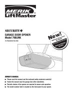
CartonInventory
Your garagedoor opener is packagedin one carton which
contains the motor unit and all parts illustrated below.
Accessorieswill depend on the model purchased.If anything is
missing, carefully check the packing material.
PARTSMAY BESTUCKIN THEFOAM.Hardwarefor assembly
and installation is shown on the next page.Savethe carton and
packing material until installation and adjustment is complete.
Door Control Button
SECURITY÷ ®
3-Function Remote Control
Rail Support A
araces_
Remote Control
Visor Clip
O
Sprocket
Coupling
Motor Unit with 2 Light Lenses
Rail Assembly
2-Conductor Bell Wire
White & White/Red
Hanging Brackets
Header/Rail
Brackets
Header Bracket
Trolley
Door Bracket
Straight Door
Arm Section
Curved Door
Arm Section
(1 Sending Eye and 1 Receiving Eye)
with attached 2-Conductor
White & White/Black Bell Wire
Safety Reversing Sensor
Mounting Bracket (2)
Safety Labels
and
Literatu re

HardwareInventory
Separateall hardwareand group as shown below for the assembly and installation procedures.
Metal Sleeve (2) C-Clip (2)
ASSEMBLYHARDWARE
Hex Bolt 1/4"-20x7/16" (14) Sprocket Coupling Sleeve Wire Clips (6)
iNSTALLATiONHARDWARE
Carriage Bolt
1/4"-20xl/2" (2)
Wing Nut
1/4"-20 (2)
_i i1ii] iii ,_
Lag Screw
5/16"-9xl-5/8" (2)
Lag Screw
5/16"-18xl-7/8" (2)
Self-Threading Screw
1/4"-14x5/8" (2)
Clevis Pin
5/16"x2-3/4" (1)
O
Ring
Fastener (3)
Hex Bolt
5/16"-18x7/8" (4)
Nut 5/16"-18 (4)
Lock Washer 5/16" (4)
Screw
6ABx1-1/4" (2)
oD
Drywall Anchors (2)
Clevis Pin
5/16"xl" (1)
o_
Handle
Insulated
Staples (30)
Screw
6-32x1" (2)
Rope
Spacer
ClevisPin
5/16"x1-1/4"(1)
o_

ASSEMBLY STEP 1
Assemb/ethe Rai/
To avoidinstallationdifficulties,do notrunthe garagedoor
openeruntil instructedto do so.
1. Openthe rail carton and removethe contents onto a levelwork
surface. Keepit cleanand free of debris while you are working.
2. Identify the rail sections and orient the sections on a flat
surface asshown. The back rail has a black gear on one end.
Theheader rail hasa black plastic rack insidethe rail on the
screw. The remaining section is the center rail.
NOTE:Usecaution whenhandling the center rail section. The
screw canslip out if the section is tipped up too far.
To prevent INJURYfrom pinching, keephandsand fingers
away from the joints while assembling the rail.
HARDWARESHOWN ACTUALSIZE
Hex Bolt 1/4-20x7/16"
Remove Cardboard Packing
Hanging Brackets
Rail Support Braces
Straight Door Arm
Header Rail Brackets
Rail Assembly
Rail Assembly @ _
(_ Remove Cardboard Packing
Sprocket Coupling
Remove
Cardboard
Packing
Back
Hex Bolts
1/4-20x7/16"
Hex Bolts
._/4-20x7/16"
Hex Bolts
1/4-20x7/16"
Hex Bolts
1/4-20x7/16"
Header Rail

Assemb/e the Raft (continued)
3. Attach rail support braces to the back rail. Loosely insert
1/4-20x7/16" hexbolts into the aligned holes of the end rail and
rail support brace(Figure1). Do not finger tighten.
4. Extendthe drive screw a few inches from the center rail, and
slide the sleeveonto the long journal (Figure2).
5. Interlock the long and short journal of the center and back
rails. Slide the sleeveover the journal connection (Figure 3).
6. Placethe c-clip onto the long journal shaft (center rail) to
ensurethat the sleevedoes not slide (Figure4).
7. Slide the center rail so that the center rail and rail braceholes
are aligned (Figure 5). Securewith bolts.
8. Tighten all hex bolts.
9. Repeatsteps 3-8 for headersection.
Metal Sleeve
HARDWARESHOWN ACTUALSIZE
C-Clip
Hex bolt 1/4-20x7/16"
Figure1
Figure4
Rail Support Brace
Rail
/
Rail Support Brace
I
Center Rail
Figure2
\__
......... Drive Screw
_ Metal Sleeve
I ......... Long Journal
[
Center Rail
Figure5
Center Rail
Rail Support Brace
Figure3 Short Journal
' ig Journal
i I Metal Sleeve
i
Rail Support Brace

ASSEMBLY STEP 2
Fasten the Rail to the Motor Unit and Install the
Trolley
NOTE:Toaid in assembly and installation, replacethefoam
packing around the motor unit. Removeit after Installation
Step 4.
1. Working on a level surface, align the rail assembly with the
motor unit, as shown.
2. Slip the coupling over the rail sprocket.
3. Slide the rail through the motor unit bracket until the coupling
fits securelyover the motor unit sprocket.
4. Align thefour bolt holesin the rail with those in the motor unit
bracket. Insertfour 1/4"-20x7/16" hexbolts. Tighten securely
with a 3/8" socketwrench.
5. Disengagetrolley by turning the releasearm down. Slide trolley
onto and along the bottom of the rail until it aligns with the
rack.Turn releasearm up. This will join the rack and the
trolley.
Hex Bolts
1/4-20x7/16"
HARDWARESHOWN ACTUALSIZE
Hex Bolt 1/4-20x7/16"
Motor Unit
Bracket
Motor Unit
Sprocket
Rail
Assembly
Release arm
Coupling
\
Rail Sprocket
1
/
Foam Packaging
Trolley-
unit
Hex Bolts
1/4-20x7/16"
10

ASSEMBLY STEP 3
AttachtheRaftBrackets
• Align rail bracketsto end of rail assembly,as shown.
• insert two 1/4"-20x7/16" hex bolts. Tighten securely with a 3/8"
socket.
Youhave nowfinishedassembfingyourgaragedoor opener.
Please read the following warningsbeforeproceeding to the
installationsection.
Rail Brackets
Rail
Hex Bolt
1/4"-B0x7/16"
Hex Bolt
1/4"-20x7/16"
HARDWARESHOWNACTUAL SiZE
Hex Bolt 1/4"-20x7/16"
iNSTALLATiON
iMPORTANT iNSTALLATiON iNSTRUCTiONS
To reduce the risk of SEVERE iNJURY or DEATH:
1. READAND FOLLOWALL iNSTALLATiONWARNINGSAND
INSTRUCTIONS.
2. install garagedoor opener ONLYon properly balancedand
lubricated garagedoor. An improperly balanceddoor may
NOTreversewhen required and could result in SEVERE
INJURYor DEATH.
3. ALL repairsto cables,spring assemblies and other
hardware MUSTbe made by atrained door systems
technician BEFOREinstalling opener.
4. DisableALL locks and removeALL ropes connectedto
garagedoor BEFOREinstalling openerto avoid
entanglement.
5. installgaragedoor opener 7' (2.13 m) or more abovefloor.
6. Mount the emergency releasewithin reach, but at least6
feet (1.8 m) abovethe floor and avoiding contact with
vehiclesto avoid accidentalrelease.
7. NEVERconnectgarage door opener to power source until
instructed to do so.
8. NEVERwear watches, rings or looseclothing while
installing or servicing opener.They could be caught in
garagedoor or opener mechanisms.
9. Installwall-mounted garage door control:
• within sight of the garage door.
• out of reachof children at minimum height of
5' (1.5 m).
• awayfrom ALL moving parts of the door.
10. Placeentrapmentwarning label on wall next to garage door
control.
11. Placemanual release/safetyreversetest label in plain view
on inside of garage door.
12. Uponcompletion of installation, test safety reversal
system. Door MUSTreverse on contact with a
1-1/2" (3.8 cm) high object (or a 2x4 laid flat) on the floor.
11

iNSTALLATiON STEP 1
Determine the HeaderBracketLocation
To prevent possible SERIOUSINJURYor DEATH:
• HeaderbracketMUST be RIGIDLYfastenedto structural
support on headerwall or ceiling, otherwise garagedoor
might NOTreversewhen required.DONOTinstall header
bracket over drywall.
• Concreteanchors MUST be usedif mounting headerbracket
or 2x4 into masonry.
• NEVERtry to loosen, move or adjust garagedoor, springs,
cables, pulleys,brackets, or their hardware,ALL of which
are under EXTREMEtension.
• ALWAYScall atrained door systems technician if garage
door binds, sticks, or is out of balance.An unbalanced
garagedoor might NOT reversewhen required.
Installation procedures vary according to garagedoor types.
Follow the instructions which applyto your door.
1. Closethe door and mark the insidevertical centefline of the
garagedoor.
2. Extendthe line onto the headerwall abovethe door.
You canfasten theheader bracket within 4' (1.22 m) of the
left or right of the door centeronly if a torsionspringor
centerbearingplate is in theway; or youcan attach it to the
ceiling(see page 13) when clearanceis minimal. (it may be
mountedon thewail upsidedown if necessary,to gain
approximately 1/2" (1 cm).)
If you need to install the headerbracket on a 2x4 (on wall or
ceiling), use lag screws (not provided) to securely fastenthe
2x4 to structural supports asshown here and on page 13.
3. Openyour door to the highest point of travel asshown. Draw
an intersecting horizontal line on the headerwall abovethe
high point:
• 3" (7.5 cm) abovethe high point for sectionaldoor and
one-piecedoor with track.
• 8" (20 cm) abovethe high point for one-piecedoor without
track.
This height will providetravel clearancefor the top edge of the
door.
NOTE:If the total number of inches exceedsthe height available
in your garage, usethe maximum heightpossible, or refer to
page 13 for ceiling installation.
HeaderWall
Unf!nished
Ceiling _ BRACKETHEADERFORMOuNTCEILINGOPTIONAL
Vertical Centerline
of GarageDoor
2x4 Structural
Supports
Header Wall
(7.5 cm)
Highest Point
of Travel
Sectional door with curvedtrack
Y
Header Wall
_====_ ,,
/Track
// Highest Point
Y of Travel
0he-piece door with horizontaltrack
Wall
Door 2° ihest
I _ Point
_Hardware i of Travel
0no-piece deer without track:
jamb hardware
Door
Header Wall
',- 8" (20 cm)
,;- Highest
Point
of Travel
Pivot
0no-piece doer without track:
pivothardware
12

INSTALLATION STEP 2
Install theHeaderBracket
You can attachthe headerbracketeither to the wall abovethe
garagedoor, or to the ceiling. Follow the instructions which will
work bestfor your particular requirements. Donot install the
headerbracketoverdrywall. If installingintomasonry,use
concreteanchors(not provided).
WALLHEADERBRACKETINSTALLATION
* Centerthe bracket on the vertical centerline with the bottom
edge of the bracket on the horizontal line asshown (with the
arrow pointing toward the ceiling).
• Mark thevertical set of bracket holes(do not usethe holes
designatedfor ceiling mount). Drill 3/16" pilot holesand fasten
the bracket securelyto a structural support with the hardware
provided.
HARDWARESHOWNACTUALSIZE
Lag Screw
5/16"-9xl -5/8"
Wall Mounting Holes
Optional
Wall Mounting Holes
Header
_iiiiiiiSJiii_iiiiiii/iiiiiiii
2x4
Structural
Support_
d"
Horizontal
Line _, _ j
I
J
Highest Point of _,_
Garage Door Travel
The nail hole is for
positioning only.
You must use lag screws
to mount the header bracket.
Garage Door
CEILINGHEADERBRACKETINSTALLATION
• Extendthe vertical centerline onto the ceiling as shown.
• Centerthe bracket on the vertical mark, no more than
6" (15 cm) from the wall. Make sure the arrow is pointing
toward the wall. Thebracket canbe mounted flush against the
ceiling when clearanceis minimal.
• Mark the side holes. Drill 3/16" pilot holes and fasten bracket
securelyto a structural support with the hardwareprovided.
Ceiling Mounting Holes
Finished
Ceiling
_
Vertical
t / _ _Header Centerline
_ Bracket : Garage Door
6" (15 cm)
Maximum
Door
S
Lag Screws
5/16"-9xl -5/8"
The nail hole is for
positioning only.
You must use lag screws
to mount the header bracket.
of Garage Door
Header Wall
13

INSTALLATION STEP 3
AttachtheRail tothe HeaderBracket
• Position the opener on the garagefloor below the header
bracket. Usepacking material asa protective base. NOTE:If the
door spring is in the wayyou'll needhelp. Havesomeone hold
theopener securely on a temporary support to allow the rail to
clearthe spring.
• Position the header/rail bracketagainst the header bracket.
• Align the bracket holesand join with a clevis pin 5/16"x2-3/4"
as shown. Spacercan be installed on either side of rail.
• Inserta ring fastenerto secure.
/Header Bracket
Ring Fastener\
Header Bracket 0
Spac2
5/16"x2-3/4" \ _ _ -
Header/Rail
Bracket
Garage
Door
_] \ Opener Carton or
/
Temporary
Support
Clevis Pin
5/16"x2-3/4"
HARDWARESHOWNACTUALSIZE
°1
0
Ring Fastener Spacer
14

iNSTALLATiON STEP 4
Install TheProtectorSystem®
Thesafety reversingsensormustbeconnected and aligned
correctlybefore the garagedooropener will movein the down
direction.
iMPORTANTiNFORMATiONABOUTTHESAFETYREVERSING
SENSOR
When properly connectedand aligned, the sensor will detect an
obstacle in the pathof its electronic beam. Thesending eye (with
an amber indicator light) transmits an invisible light beamto the
receiving eye (with a green indicator light), if an obstruction
breaks the light beamwhile the door is closing, the door will stop
and reverseto full open position, and the opener lights will flash
10 times.
Theunits must be installed inside the garageso that the sending
and receivingeyes face eachother across the door, no morethan
6" (15 cm) abovethefloor. Either can be installed on the left or
right of the door as long as the sun nevershines directly into the
receiving eye lens.
Themounting brackets are designedto clip onto the track of
sectional garagedoors without additional hardware.
Be sure power is NOTconnectedto the garagedoor opener
BEFOREinstalling the safety reversing sensor.
To prevent SERIOUSINJURYor DEATHfrom a closing garage
door:
• Correctly connect and align the safety reversing sensor. This
required safety device MUSTNOTbe disabled.
• install the safety reversing sensor so beamis NOHIGHER
than 6" (15 cm) abovegaragefloor.
If it is necessaryto mount the units on the wail, the brackets
must be securelyfastenedto a solid surface such asthe wall
framing. Extensionbrackets (seeAccessories) are availableif
needed.If installing in masonry construction, add a pieceof wood
at eachlocation to avoid drilling extra holesin masonry if
repositioning is necessary.
Theinvisible light beam path must be unobstructed. No part of
the garagedoor (or door tracks, springs, hinges, rollers or other
hardware) may interrupt the beamwhile the door is closing.
Facing the door from inside thegarage
15

INSTALLINGTHE BRACKETS
Besure power to the opener is disconnected. Install and align
the brackets so the sensors will face eachother across the garage
door, with the beam no higher than 6"(15 cm) abovethe floor.
They may be installed in one of three ways, as follows.
Garage doortrackinstallation(preferred):
* Slip the curved arms over the rounded edge of each door track,
with the curved arms facing the door. Snap into placeagainst
the side of the track. It should lie flush, with the lip hugging the
back edge of the track, asshown in Figure1.
If your door track will not support the bracket securely,wall
installation is recommended.
Waftinstallation(Figure2 & 3):
• Placethe bracketagainst the wall with curved arms facing the
door. Besure there is enough clearancefor the sensor beamto
be unobstructed.
* If additional depth is needed,an extensionbracket (see
Accessories)or wood blocks can be used.
* Usebracket mounting holes asa template to locate and drill
(2) 3/16" diameter pilot holeson the wall at eachside of the
door, no higher than 6" (15 cm) abovethefloor.
* Attach brackets to wall with lag screws (not provided).
* If using extensionbrackets or wood blocks, adjust right and
left assembliesto the same distanceout from the mounting
surface. Make sure all door hardwareobstructions are cleared.
Floorinstallation(Figure4):
* Usewood blocksor extensionbrackets (seeAccessories)to
elevatesensor bracketsso the lenseswill be no higher than
6" (15 cm) abovethe floor.
• Carefullymeasure and place right and left assembliesat the
same distanceout from the wall. Besure all door hardware
obstructions are cleared.
• Fastento the floor with concrete anchors as shown.
Figure1
_ Door
II Tr::
_ Senso_r._
acket
DOOR TRACK MOUNT (RIGHT SIDE)
Indicator
Light
Figure2
WALL MOUNT (RIGHT SIDE)
Figure3
Fasten Wood Block to Wall with
Lag Screws (Not Provided)
Indicator
Light Sensor
.__ Bracket
7L b -7 |- (Not Provided)
Lens --_
(Provigd with
Extension ._._-"
Bracket)
WALL MOUNT (RIGHT SIDE)
iiiiiiiiiiiiiiii!ili!Bracket
iiiiiiiii;ii (See Accessories)
ii!iliiiiiiiiiiiiiiiiii!i:i/J_ (Providedwith
!i!!it ExtensionBracket)
iiiiiiiii:iiiiii/ -
Lens Light
Figure4 FLOOR MOUNT (RIGHT SIDE)
HARDWARESHOWNACTUALSIZE
Carriage Bolt Wing Nut Staples
1/4"-20x 1/2" 1/4"-20
J
-- ttach with
Concrete Anchors
(Not Provided)
Light
Bracket
16

MOUNTINGANDWIRINGTHESAFETYSENSORS
• Slide a 1/4"-20xl/2" carriage bolt headinto the slot on each
sensor. Usewing nuts to fastensensors to brackets,with
lenses pointing toward eachother across the door. Besure the
lens is not obstructed by a bracket extension (Figure5).
• Fingertighten the wing nuts.
RecommendedWire Routing
1. Using insulated staples, run the wires from both sensors to the
rail at the door header (Figure6).
2. Runthe wires through wire clip at the top of the rails.
NOTE:If your access door is near thegarage door, you may
choose to instafl the door control at this time and run the door
control wire along the raft with the sensor wires. If you choose
this option, follow instructions 1-3 on page 20.
Figure5
Wing Nut
1/4"-20
Lens
Carriage Bolt
1/4"-20x 1/2"
HARDWARESHOWNACTUALSIZE
Wing Nut Staples
1/4 "-20
Wire Clip
Figure6
Sensor Wire
Wire Clip
Bell Wire
Safety Reversing
Sensor
Invisible Light Beam
Protection Area
Safety Reversing
Sensor
17

INSTALLATION STEP 5
Positionthe Opener
Follow instructions which applyto your door type as illustrated.
SECTIONALDOORORONE-PIECEDOORWITH TRACK
A 2x4 laid flat is convenient for setting an ideal door-to-rail
distance.
• Removefoam packaging.
• Raisethe opener onto a stepladder.You will need help at this
point if the ladder is not tall enough.
• Openthe door all the way and placea 2x4 laid flat on the top
section beneaththe rail.
• If the top section or panel hits the trolley whenyou raisethe
door, pull down on the trolley releasearm to disconnect inner
and outer sections. Slidethe outer trolley toward the motor
unit. Thetrolley can remaindisconnected until Installation
Step 13 is completed.
ENGAGED
Trolley
-- Release Arm --
RELEASED
To prevent damageto garage door, rest garage door opener
rail on 2x4 placedon top section of door.
J
_:::: _:__ ____ iI
oor
ONE-PIECEDOORWITHOUTTRACK
A 2x4 on its side is convenientfor setting an ideal door-to-rail
distance.
• Removefoam packaging.
• Raisethe opener onto a stepladder.You will need help at this
point if the ladder is not tall enough.
• Openthe door all the way and placea 2x4 on its side on the
top section of the door beneaththe rail.
• Thetop of the door should be levelwith thetop of the motor
unit. Donot position the opener more than 4" (10 cm) above
this point.
18

INSTALLATION STEP 6
Hangthe Opener
Threerepresentativeinstallations are shown. Yours may be
different. Hangingbrackets should be angled (Figure 1) to provide
rigid support. Onfinished ceilings (Figure2 and Figure3), attach
a sturdy metal bracket to structural supports before installing the
opener.This bracketand fastening hardwareare not provided.
1. Measurethe distancefrom eachside of the motor unit to the
structural support.
2. Cut both piecesof the hanging bracketto required lengths.
3. Drill 3/16" pilot holes in the structural supports.
4. Attach one end of eachbracketto a support with
5/16"-18xl -7/8" lag screws.
5. Fastenthe opener to the hanging brackets with 5/16"-18x7/8"
hex bolts, lock washers and nuts.
6. Checkto make sure the rail is centered over the door (or in line
with the headerbracket if the bracket is not centeredabovethe
door).
7. Removethe 2x4. Operatethe door manually. If the door hits
the rail, raisethe header bracket.
NOTE:DONOTconnectpower to openerat this time.
To avoid possible SERIOUSINJURYfrom afalling garage door
opener,fasten it SECURELYto structural supports of the
garage.Concreteanchors MUSTbe usedif installing ANY
brackets into masonry.
Figure1
Supports
Measure ',
Distance
Bolt 5/16"- 18x7/8"
Lock
Nut 5/16"-18
\
Lag Screws
5/16"-18xl -7/8"
Figure2 Hidden .... -
Support _ _- -
.-- Lag Screws
_ _- 5/16"-18xl-7/8"
Bolt 5/16"- 18x7/8"
Lock Washer 5/16"_
Nut 5/16"-18
FINISHED CEILING
(Not Provided)
Bolt 5/16"-18x7/8"
Lock Washer 5/16"
Nut 5/16"-18
HARDWARESHOWNACTUALSIZE
D,,,,,,,,,,D@
Hex Bolt
5/16"-18x7/8" Nut 5/16"- 18 Lock Washer 5/16"
Figure3
Lag Screws
5/16"-18xl -7/8"
Bolt 5/16"-18x7/8"
Lock Washer 5/16'
Nut 5/16"-18
(Not Provided)
Bolt 5/16"-18x7/8"
Lock Washer 5/16"
Nut 5/16"-18
19

INSTALLATION STEP 7
Install the DoorControl
Locate door control within sight of door, at a minimum height of
5 feet (1.5 m) where small children cannot reach,away from
moving parts of door and door hardware.
1. Strip 1/4" (6 mm) of insulation from one end of bell wire and
connectto the two terminal screws on back of door control by
color: white to 2 and white/red to 1.
2. Fastenthe Door Control Button securelywith 6ABx1-1/2"
screws. If installing into drywall, drill 5/32" holesand usethe
anchors provided.
3. Runbell wire up wall and across ceiling to motor unit. Use
insulated staplesto secure wire in several places. Donot pierce
wire with a staple,creating a short or open circuit.
4. Connectthe bell wire to the quick-connectterminals on the
motor unit panel:white to white; white/red to red.
5. Position the antennawire as shown.
6. Usetacks or staplesto permanently attachentrapment warning
label to wall near door control, and manual release/safety
reversetest label in a prominent location on inside of garage
door.
NOTE:DONOTconnectpower and operateopener at this time.
Thetrolley will travel to the furl openposition but will not return to
the close position until the sensor beamis connectedand properly
aligned.
To prevent possible SERIOUSINJURYor DEATHfrom
electrocution:
* Besure power is NOTconnected BEFOREinstalling door
control.
* ConnectONLYto 24 VOLTlow voltage wires.
To prevent possible SERIOUSINJURYor DEATHfrom a closing
garagedoor:
* Install door control within sight of garagedoor, out of reach
of children at a minimum height of 5 feet (1.5 m), and away
from ALL moving parts of door.
* NEVERpermit children to operateor play with door control
push buttons or remote control transmitters.
. Activate door ONLYwhen it can be seenclearly, is properly
adjusted, and there are no obstructions to door travel.
. ALWAYSkeepgarage door in sight until completely closed.
NEVERpermit anyoneto cross path of closing garage door.
HARDWARESHOWNACTUALSIZE
Screw 6ABx1-1/2" Insulated
Lighted Door Control Button Drywall Anchors Staples
Terre lna'
(BACK VIEW)
DOOR CONTROL BUTTON
Quick-Connect
Terminals
To release or insert wire,
push in tab with
screwdriver tip
Strip wire 7/16" Red_
(11 mm)
7/16" (11 mm)l
Door Control
Connections
White Grey
Antenna
20
/