NEC Display Solutions of America, Inc.
P525WL/P525UL/P605UL Installation Guide
Desktop and Ceiling Mount Rev 1.1
www.necdisplay.com P525WL/P525UL/P605UL Page 1 of 8
Contents
Product Description, Lens Specs, Screen/Aspect Ratio
Notes Pg 1
Distance Charts and Formulas Pg 2
Ceiling Mount/Desktop Installation Pg 3
Lens Shift Adjustable Range Pg 4
Cabinet Dimensions Pg 5-6
Ventilation Requirements, Input Panel and Control Panel Pg 7
Control Codes Pg 8
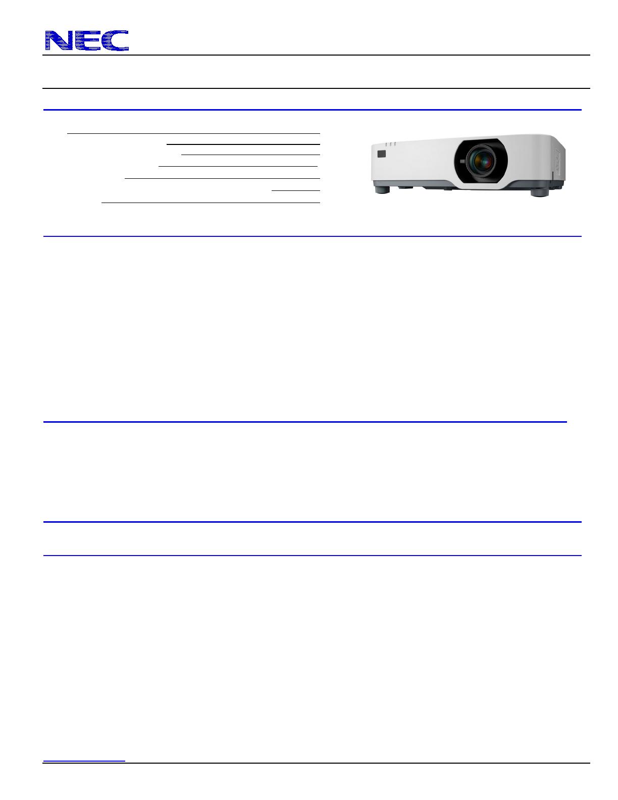
Product Description
Type: 3 panel LCD projector, Dimensions: 18.9”(W) x 5.6”(H) x 16.0”(D)
0.64” p-Si TFT w/MLA Weight: 21.3 lbs
Resolution: P525WL: 1280 x 800 (16:10) Brightness: P525WL: 5200 Lumens
P525UL/P605UL: 1920 x 1200 (16:10) P525UL: 5200 Lumens
P605UL: 6000 Lumens
Fan Noise: P525WL/P525UL:24 dB / 22dB @ 1 meter
P605UL: 25 dB / 19dB @ 1 meter
Power Consumption: P525WL: 320W (max) BTU’s: P525WL: 1091.9 BTU/hour (max)
P525UL: 330W (max) P525UL: 1126.0 BTU/hour (max)
P605UL: 367W (max) P605UL: 1252.3 BTU/hour (max)
Network Ready: Integrated wired (RJ45) and (optional) wireless adapter
Manual: Horizontal & Vertical Lens Shift, Zoom, Focus
Lens Specifications
Throw Ratio: 1.23 – 2.0:1 (for 100” diagonal) Focal Length: 17.2mm – 27.6mm
Offset Angle: 4.8° - 8.0° (for 100” diagonal) F/#: 1.5 – 2.1
Screen Sizes: 25” - 300” diagonal Manual Focus/Manual Zoom/Manual Lens Shift
Screen/Aspect Ratio
4:3, 16:9 and 16:10 screens are fully supported with proper aspect ratio control for both type sources using NEC developed scaling
technology. Menu selections have settings for each screen type and aspect ratio control for each source type.
Notes
For screen sizes not indicated on the projection tables, use the formulas below.
If the figures on the tables do not match the results of formulas, use the figures in the table..
• Distances are in inches, for millimeters multiply by 25.4.
• Distances may vary ±5%.


