Aigis Mechtronics HS9384-2H Operating instructions
- Category
- Camera housings
- Type
- Operating instructions
This manual is also suitable for

I N S T A L L A T I O N A N D O P E R A T I N G I N S T R U C T I O N S
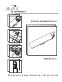
OUTDOOR CAMERA HOUSINGS
HS9384 SERIES

2
SAFETY PRECAUTIONS
T
his label may appear on the bottom of the unit due to space
limitations.
The lightning flash with an arrowhead symbol within an
equilateral triangle is intended to alert the user to the
presence of uninsulated "dangerous voltage" within the
product's enclosure that may be of sufficient magnitude
to constitute a risk of electric shock to persons.
The exclamation point within an equilateral triangle is
intended to alert the user to presence of important
operating and maintenance (servicing) instructions in the
literature accompanying the appliance.
1 UNPACKING
Unpack carefully. This is electromechanical equipment and
should be handled with care.
Check for the following items:
• Verify the unit model number.
• Verify that parts listed as follows have been included. See
INSTALLATION.
CAUTION: TO REDUCE THE RISK OF ELECTRICAL
SHOCK, DO NOT OPEN COVERS. NO USER SERVICEABLE
PARTS INSIDE. REFER SERVICING TO QUALIFIED SERVICE
PERSONNEL.
IMPORTANT SAFEGUARDS
1. Read Instructions - All the safety and operating instructions should be read before the
u
nit is operated.
2
. Retain Instructions - The safety and operating instructions should be retained for future
r
eference.
3
. Heed Warnings - All warnings on the unit and in the operating instructions should be
adhered to.
4
. Follow Instructions - All operating and use instructions should be followed.
5
. Cleaning - Unplug the unit from the outlet before cleaning. Do not use liquid cleaners or
aerosol cleaners. Use a damp cloth for cleaning.
6
. Attachments - Do not use attachments not recommended by the product manufacturer
a
s they may cause hazards.
7. Accessories - Do not place this unit on an unstable stand, tripod, bracket, or mount. The
unit may fall, causing serious injury to a person and serious damage to the unit. Use only
with a stand, tripod, bracket, or mount recommended by the manufacturer or sold with
t
he product. Any mounting of the unit should follow the manufacturer's instructions and
s
hould use a mounting accessory recommended by the manufacturer.
An appliance and cart combination should be moved with care. Quick stops, excessive
force, and uneven surfaces may cause the appliance and cart combination to overturn.
8. Ventilation - Openings in the enclosure, if any, are provided for ventilation, to ensure
reliable operation of the unit, and to protect it from overheating. These openings must
not be blocked or covered. This unit should not be placed in a built-in installation unless
p
roper ventilation is provided or the manufacturer's instructions have been adhered to.
9. Power Sources - This unit should be operated only from the type of power source indicat-
e
d on the marking label. If you are not sure of the type of power supply you plan to use,
c
onsult your dealer or local power company. For units intended to operate from battery
power or other sources, refer to the operating instructions. This equipment is to be isolat-
ed from the mains supply by a limited power source as specified in EN60950:1992 Clause
2
.11.
1
0. Grounding or Polarization - This unit may be equipped with a polarized alternating-cur-
r
ent line plug (a plug having one blade wider than the other). This plug will fit into the
p
ower outlet only one way. This is a safety feature. If you are unable to insert the plug
f
ully into the outlet, try reversing the plug. If the plug should still fail to fit, contact your
e
lectrician to replace your obsolete outlet. Do not defeat the safety purpose of the
p
olarized plug.
Alternately, this unit may be equipped with a 3-wire grounding-type plug, a plug having a
t
hird (grounding) pin. This plug will only fit into a grounding-type power outlet. This is a
safety feature. If you are unable to insert the plug into the outlet, contact your electrician
t
o replace your obsolete outlet. Do not defeat the safety purpose of the grounding-type
plug.
11. Power Cord Protection - Power supply cords should be routed so that they are not like-
ly to be walked on or pinched by items placed upon or against them, paying particular
attention to cords and plugs, convenience receptacles, and the point where they exit
from the appliance.
12. Power Lines - An outdoor system should not be located in the vicinity of overhead power
lines or other electric light or power circuits or where it can fall into such power lines or
circuits. When installing an outdoor system, extreme care should be taken to keep from
touching such power lines or circuits as contact with them might be fatal. U.S.A. models
only - refer to the National Electrical Code Article 820 regarding installation of CATV sys-
tems.
13. Overloading - Do not overload outlets and extension cords as this can result in a risk of
fire or electric shock.
14. Object and Liquid Entry - Never push objects of any kind into this unit through openings,
as they may touch dangerous voltage points or short out parts that could result in a fire
or electric shock. Never spill liquid of any kind on the unit.
15. Servicing - Do not attempt to service this unit yourself as opening or removing covers
may expose you to dangerous voltage or other hazards. Refer all servicing to qualified
service personnel.
16. Damage Requiring Service - Unplug the unit from the outlet and refer servicing to quali-
fied service personnel under the following conditions:
a. When the power supply cord or plug is damaged.
b. If liquid has been spilled or objects have fallen into the unit.
c. If the unit has been exposed to water and/or inclement weather (rain, snow, etc.).
d. If the unit does not operate normally by following the operating instructions. Adjust
only those controls that are covered by the operating instructions, as an improper
adjustment of other controls may result in damage and will often require extensive
work by a qualified technician to restore the unit to its normal operation.
e. If the unit has been dropped or the cabinet has been damaged.
f. When the unit exhibits a distinct change in performance--this indicates a need for
service.
17. Replacement Parts - When replacement parts are required, be sure the service techni-
cian has used replacement parts specified by the manufacturer or have the same charac-
teristics as the original part. Unauthorized substitutions may result in fire, electric shock,
or other hazards.
18. Safety Check - Upon completion of any service or repairs to this unit, ask the service
technician to perform safety checks to determine that the unit is in proper operating
condition.
19. Coax Grounding - If an outside cable system is connected to the unit, be sure the cable
system is grounded. U.S.A. models only--Section 810 of the National Electrical Code,
ANSI/NFPA No.70-1981, provides information with respect to proper grounding of the
mount and supporting structure, grounding of the coax to a discharge unit, size of
grounding conductors, location of discharge unit, connection to grounding electrodes,
and requirements for the grounding electrode.
20. Lightning - For added protection of this unit during a lightning storm, or when it is left
unattended and unused for long periods of time, unplug it from the wall outlet and dis-
connect the cable system. This will prevent damage to the unit due to lightning and
power line surges.
Hardware Kit
Quantity Part Description
3 Cable Tie
2 BHCS,
1
⁄4-20 x
1
⁄4-inch
1 BHCS,
1
⁄4-20 x
5
⁄8-inch
1 BHCS,
1
⁄4-20 x
3
⁄4-inch
3 BHCS,
1
⁄4-20 x
1
⁄2-inch
1 BHCS,
1
⁄4-20 x
3
⁄8-inch
1 BHCS,
1
⁄4-20 x 1
1
⁄4-inch
1 0.4 mm (0.016-inch) Plastic Spacer
1 1.65 mm (0.065-inch) Plastic Spacer
1 3.9 mm (0.154-inch) Plastic Spacer
1 7.4 mm (0.292-inch) Plastic Spacer
1 9.8 mm (0.385-inch) Plastic Spacer
1
3
⁄8-inch NPT Plug
2 Pull Seals
If an item appears to have been damaged in shipment, replace
it properly in its carton and notify the shipper. If any items
are missing, notify Aigis Mechtronics.
The shipping carton is the safest container in which the unit
may be transported. Save it for possible future use.
2 SERVICE
If the unit ever needs repair service, the customer should
contact Aigis Mechtronics for return authorization and ship-
ping instructions.

3
3 CARE AND MAINTENANCE
Clean the viewing window as needed with a mild, nonabra-
sive detergent in water and a soft cloth.
4 DESCRIPTION
T
he HS9384 Series of environmental housings are attractive
aluminum enclosures designed for outdoor CCTV camera
installations.
4.1 Enclosure Rating
4.1.1 NEMA-3R and IP54
The HS9384 Series housings include a "breather" hole in the
front end cap. The "breather" hole prevents the accumula-
tion of moisture inside the housing when installed in areas of
high humidity. With the "breather" hole open, the HS9384
Series housings meet the enclosure rating requirements of
NEMA-3R and IP54.
4.1.2 NEMA-6P and IP68
For installations requiring an enclosure rating of NEMA-6P or
IP68, the breather hole must be plugged using the pull seal
provided in the hardware kit. Refer to Final Assembly under
INSTALLATION for proper installation.
5.2 Tools Required
• Flat blade screwdriver
• Phillips head screwdriver
•
5
⁄32-inch (or 4 mm) hex wrench
•
5
⁄16-inch (or 8 mm) hex wrench
• Adjustable wrench
• Wire cutter/stripper/crimper tool
5.3 Cable Requirements
Video Transmission (Coaxial)
Cable Type: RG-59/U (Runs < 1000 ft)
RG-11/U (Runs < 2000 ft)
Cable Size: Outside diameter between 4.6 mm
(0.181 in) & 7.9 mm (0.312 in)
Cable Shape: Round
Shield: ≥ 93% Braided Copper Shield
Center Conductor: Stranded Copper Center
DC Resistance: ≤ 15 Ohms/1000 ft (RG-59/U)
≤ 6 Ohms/1000 ft (RG-11/U)
Cable Impedence: 75 Ohm
Agency Rating: UL
Environmental: Outdoor rated
Temperature Rating: ≥ 80 °C
Sources: Belden 9259
Belden 9238
Input Power Cord - North American
Cable Type: SJTOW-A rated
Cable Size: Outside diameter between 4.3 mm
(0.170 in) & 11.9 mm (0.470 in)
Cable Shape: Round
Conductors: 3 conductor version and
2 conductor version
Agency Rating: UL/C.S.A., UL VW-1
Environmental: Outdoor rated
Temperature Rating: 105 °C
Voltage Rating: 300 V
Sources: Belden 19506
Belden 19509
Northwire 573939
5 INSTALLATION
This installation should be made by a qualified ser-
vice person and conform to all local codes.
5.1 Model Designation
Model Rated Voltage Voltage Nominal
No. Input Range Output Power
2
HS9384-2H 24 VAC, 21.6 to 26.4 —— 30 W
50/60 Hz
HS9384-2H-9 24 VAC, 21.6 to 26.4 —— 30 W
50/60 Hz
HS9384-5H
1
230 VAC, 207 to 253 24 VAC, 30 W
50/60 Hz 50/60 Hz
HS9384-6H
1
115 VAC, 108 to 132 24 VAC, 30 W
50/60 Hz 50/60 Hz
1. The power transformers included with these housings are
used to provide heater power and can be used to provide iso-
lated camera power.
2. Heater requires 10 watts.
Do Not Exceed 30 VAC Input on 24 VAC models.
Operation above 30 VAC violates low voltage operation
(Class 2 Specifications). Normal operation is 24 VAC.
Maximum Camera/Lens Size:
HS9384-2H: Accepts cameras up to 64 W x 54 H mm
(2.5 x 2.1 in), lenses up to 67 W x 75 H mm (2.6 x 2.9 in),
and camera/lens combinations up to 355 mm (14.0 in).
HS9384-2H-9: Accepts cameras up to 64 W x 54 H mm
(2.5 x 2.1 in), lenses up to 67 W x 75 H mm (2.6 x 2.9 in),
and camera/lens combinations up to 146 mm (5.75 in).
HS9384-5H & HS9384-6H: Accept cameras up to 64 W
x 54 H mm (2.5 x 2.1 in), lenses up to 67 W x 75 H mm
(2.6 x 2.9 in), and camera/lens combinations up to 292 mm
Input Power Cord - European
Cable Type: H05RN-F3G0.75 and
H05RN-F3G1.00
Cable Size: Outside diameter between 4.3 mm
(0.170 in) & 11.9 mm (0.470 in)
Cable Shape: Round
Conductors: 3 conductor version and
2 conductor version
Agency Rating: VDE
Environmental: Outdoor rated
Sources: Olflex 1600252
Olflex 1600253

4
5.6.1 General
1. The dual male threaded portion of the three liquid tight
fittings, two NPT
1
⁄2-inch, and one NPT
3
⁄8-inch, located in
the rear of the cradle, are provided preinstalled. Do not
remove or loosen these parts. They have been installed
to a specified torque to prevent entrance of water. The
two large fittings are supplied with seal glands for cables
with diameters from 4.3 mm (0.17-inch) to 11.9 mm
(0.47-inch). The small fitting will accept cables with diam-
eters from 4.6 mm (0.181-inch) to 7.9 mm
(0.312-inch) (see Figure 3).
Be sure to securely tighten all fittings to
ensure a liquid-tight seal. Failure to do so
could allow water to enter the housing and
damage the camera and lens.
1.2 Zoom Lens Cameras: Allow 3/16-inch (5 mm) clearance
from the front face of the lens to the front faceplate of the
c
radle during the camera/lens assembly. This clearance
provides the necessary space for the lens to extend out-
ward when zooming. Secure both the camera and the lens
to the cradle with the
1
⁄4 -20 BHCS and appropriate plastic
s
pacer.
5.6 Camera/Lens Wiring
WARNING: Only use the cables specified under
INSTALLATION, Cable Requirements for
wiring of all cameras and lenses.
1/4-20 Screws
Spacers
Seal Cap
Seal Gland
Dual Male Portion
Retention Screw
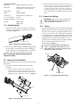
Figure 1 Removing Cradle Assembly
2. Remove the cradle assembly by simultaneously grasping
the rear handle and housing shell, and then pulling the
cradle assembly out of the housing. Be sure to keep the
edges of the end caps clean and free of scratches.
Note: Do not push against the front glass to
remove the cradle.
5.5 Camera/Lens Installation
With the cradle removed from the housing, follow all of the
steps below.
1. Place the camera/lens combination into the cradle
assembly.
1.1 Fixed Lens Cameras: Position the camera/lens 1 mm
(0.04-inch) away from the faceplate. The camera/lens is
secured to the cradle with a
1
⁄4-20 button head cap screw
(BHCS) and the appropriate plastic spacer (see Figure 2).
Figure 2 Mounting Camera and Lens
Figure 3 Liquid Tight Fitting Assembly
Lens Control Cable
Cable Type: Jacketed multiconductor cable
C
able Size: Outside diameter between 4.3 mm
(0.170 in) & 11.9 mm (0.470 in)
Cable Shape: Round
S
hield: Overall shielding
Conductors: Stranded 20 to 16 AWG wire
No. of Conductors: 4 and 8
C
onductor Insulation: Color coded
Sources: Belden 9552
Belden 9554
5.4 Cradle Removal
1. Remove the cradle from the housing by lowering the
retaining screw completely on the bottom rear of the
housing (see Figure 1).

5
If a sealant is to be used, be sure it is a neutral cure type.
Sealants that release acetic acid may harm camera electronics.
If it is necessary to use a PG type conduit, an NPT to PG
conversion kit (HS9384NPT) can be purchased separately.
Use of drip loops is recommended on the
wiring outside of the rear end cap.
5.6.2 Plug Insertion
I
f no lens control or feed-through wiring will be used,
remove the preinstalled
3
⁄8-inch liquid-tight fitting from the
small bottom center hole and install the
3
⁄8-inch NPT plug
provided. Use a
5
⁄16-inch (or 8 mm) hex wrench to tighten.
Failure to do so will allow water to enter and cause damage
to all electronic parts (see Figure 4).
3/8-inch NPT Plug
Figure 4
3
⁄8-inch NPT Plug Insertion
Liquid Tight Fitting
(Shown Underneath)
CCD Camera
WAGO Connectors
(After Connecting Wires,
Push Into Cavity)
Power Cable
Tie Wraps
Fuse Holder
Transformer
5.6.3 Power Connections
The HS9384-5H, and the HS9384-6H housings allow the use
of 24 VAC cameras, regardless of the supply voltage to the
housing. This is achieved through the use of a transformer in
the housing. The transformer's primary supply power will
vary, depending on the model of housing, see Section 5.1
Model Designation. In the 115 volt and 230 volt models,
the transformer also supplies 24 VAC power to the integral
window heater/defogger.
Refer to the following model housing sections for your
model’s wiring procedure.
1. Use the left liquid-tight fitting of the housing to route the
power wire into the housing (see Figure 5).
Figure 5 Power Connections
3. Pull any excess wire out of the cradle assembly and tighten
the fitting to 8.5 N
.
m to 9.0 N
.
m (75 in
.
lb to 80 in
.
lb). This
torque rating is approximately 1 to 1
1
⁄2 turns past the point
where the fitting starts to grip the wire. Failure to do so
will allow water to enter and damage all electronic parts.
Use a tie wrap (included) to provide strain relief on the
power cord at the exit point (inside unit).
Be sure to securely tighten all fittings to ensure
a liquid-tight seal. Failure to do so could allow
water to enter the housing and damage the
camera and lens.
M4 Screw
Terminal Lug
2. A screw/terminal lug is provided for securing a safety
ground. Attach the terminal lug to the cradle using the
M4 x 10 screw provided (see Figure 6).
Figure 6 Securing Ground Wire
5.6.4 HS9384-6H Housings
The HS9384-6H housings can easily be used with either
115 volt or 24 volt cameras.
The internal transformer provides 24 VAC for both the
heater/defogger and 24 volt camera power (see Figure 5).
For 115 volt cameras:
1. Installing a 115 volt camera into the HS9384-6H housing
requires inserting both the field supply wires (115 VAC)
and a section of hook-up wire (not included, minimum
20 AWG wire) into the unused side of the Wago
connectiors (provided), then connecting the other end of
the hook-up wire to the camera’s 110 VAC input.
Repeat for pins 1 and 6 (see Figure 7).
2. The secondary flying leads (white/black striped) will not
be used in this application and should be taped to
prevent shorting. See wiring diagram Figure 7 for
clarification and Figure 5 for power connection
drawings.
115 VAC
Input
Red
24 VAC
To Heater/Defogger
White/
Black
Striped
To Heater/Defogger
Red
No Connection
(Tape)
White/
Black
Striped
6
5
2
1
12
11
8
7
To Camera 115 VAC
Supply
115 VAC
Wago
To Camera 115 VAC
Supply
115 VAC
Wago
Black
White
Figure 7 HS9384-6H Transformer Wired for 115
Volt Camera

6
5.6.6 HS9384-5H Housings
These housings require connection to 230 VAC and are
designed to be used where site power is 230 volts.
The HS9384-5H housings can easily be used with either 230
volt or 24 volt cameras.
The internal transformer provides 24 VAC for both the
heater and 24 volt camera power.
Do not remove the transformer insulator. No
user serviceable parts are underneath.
115 VAC
Input
White
Red
24 VAC
White/
Black
Striped
To Heater/Defogger
Red
White/
Black
Striped
6
5
2
1
12
11
8
7
To Camera
Wago
Wago
Black
Brown
Black
To Camera
To Heater/Defogger
To Heater/Defogger
No Connection
To Camera
Blue
Blue
230 VAC
Input
24 VAC
White/
Black
Striped
White/
Black
Striped
6
5
1
2
12
11
8
7
Supply
Supply
(Tape)
Wago
Wago
Brown
Red
To Camera
Blue
Red
24 VAC
230 VAC
Input
White/
Black
Striped
White/
Black
Striped
6
5
1
2
12
11
8
7
To Heater/Defogger
To Heater/Defogger
For 24 volt cameras:
1. Installing a 24 volt camera into the HS9384-6H housing
utilizes the internal transformer for camera power.
2. Connect the supply (115 VAC) to the primary flying
leads of the transformer (white wire/pin 1, black wire/pin
6
). Use the wago connectors provided for this
connection.
3. Connect the secondary flying leads (white/black striped
wires/pins 7 and 12) to the camera's 24 volt input. See
w
iring diagram Figure 8 for clarification and Figure 5
for power connection drawings.
Figure 8 HS9384-6H Transformer
Wired for 24 Volt Camera
5.6.5 HS9384-2H Housings
These housings are to be connected to 24 VAC only and are
designed to be used where site power is 24 volts.
The HS9384-2H housings are designed to be used with 24 volt
cameras only.
1. Connect the supply (24 VAC) to the unoccupied sides of
the gray Wago connectors.
2. Connect the flying leads (white and black) to the
camera's 24 volt input.
For 230 volt cameras:
1. Installing a 230 volt camera into the HS9384-5H housing
requires inserting both the field supply wire (115 VAC)
a
nd a section of hook-up wire (not included, minimum
20 AWG wire) into the unused side of the Wago
connectors (provided), then connecting the other end of
the hook-up wire to the camera’s 230 VAC input.
R
epeat for pins 1 and 6. (see Figure 9).
2. The secondary flying leads (white/black striped) will not
be used in this application and should be taped to
prevent shorting. See wiring diagram Figure 9 for
clarification and Figure 5 for power connection
drawings.
Figure 9 HS9384-5H Transformer
Wired for 230 Volt Camera
For 24 volt cameras:
1. Installing a 24 volt camera into the HS9384-5H housing
utilizes the internal transformer for camera power (see
Figure 10).
2. Connect the supply (230 VAC) to the Wago connectors
(provided).
3. Connect the secondary flying leads (white/black) to the
camera's 24 volt input. Refer to the wiring diagram for
clarification.
Figure 10 HS9384-5H Transformer
Wired for 24 Volt Camera

7
2. If using a pan/tilt with a feed-through cable, insert
the camera/lens function cable in through the right fitting
at the rear of the cradle. Wire the functions as described
above or as needed.
Use of drip loops is not recommended on the wiring
outside of the rear end cap.
5.7 Video Coax Connection
WARNING: Only use the cables specified under
INSTALLATION, Cable Requirements for wiring
of the video coax connection.
1. Install the seal cap portion of the large liquid tight fitting
o
n the video coax cable and pull the cable through the
right fitting on the rear end of the cradle.
2
. Attach the BNC connector to the coax and connect it to
the camera. Pull any excess wire out of the cradle
assembly and tighten approximately 1 to 1
1
⁄2 turns past
the point where the fitting starts to grip the wire. Failure
to do so will result in water damage to all electronic
parts. Use a tie wrap (included) to provide strain relief on
the video cable at the exit point (inside unit).
3. If lens control is used, pull cable through the small
bottom fitting. If lens control is not used, install the
3
⁄8-inch NPT plug provided in the unused, small center
NPT hole.
Be sure to securely tighten all fittings to ensure a
liquid-tight seal. Failure to do so could allow water to
enter the housing and damage all electronics.
5.8 Lens Wiring
WARNING: Only use the cables specified under
INSTALLATION, Cable Requirements for wiring of
the lens control.
1. If installing a zoom lens, insert the lens control
cable with the installed seal cap in through the bottom
fitting at the rear of the cradle. Attach the lens wiring
to the lens mating connector and connect it to the lens.
If the mating connector is not available, connect directly
to the lens cable.
NOTE: See specification on lens cord for correct plug
connection.
Be sure to securely tighten all fittings to ensure a
liquid-tight seal. Failure to do so could allow water to
enter the housing and damage the camera and lens.
5.9 Final Assembly
5.9.1 Pull Seal Installation
If the breather hole is open, do NOT mount the
housing in a position where the front end cap is
pointed upward.
To maintain enclosure protection ratings of NEMA-6P and
IP68, the pull seal (provided in the hardware kit) must be
installed in the front end cap. It is recommended that the
pull seal be installed in a cool, dry environment to prevent
trapping moisture inside the housing (see Figure 11).
NOTE: Pull seal installation allows the housing's front end
cap to be pointed upward.
Long End
Head
Front of
Endcap
Pull Seal
Breather Hole
Cradle
Front Face
Breather Hole
Figure 11 Breather Hole
Proper installation of the pull seal is as follows:
1. Remove the cradle assembly from the housing.
2. Obtain a rubber pull seal from the hardware kit. An
extra pull seal is provided (see Figure 12).
Figure 12 Pull Seal
3. Insert the long end of the pull seal into the breather hole
starting from the front side of the endcap
(see Figure 13).
Figure 13 Inserting the Pull Seal
Front Endcap
Rear Face of Head Should
Be Flush with Front Face
of Front Endcap
Grip and Pull
Figure 14 Installing the Pull Seal
4. Grip the pull seal's long end from the back of the front
endcap. Steadily pull the long end until the head of the pull
seal is flat against the front of the endcap (see Figure 14).
NOTE: The Pull Seal's long end will stretch when pulled
through the breather hole.

CAUTION: If a pull seal is installed in the
breather hole, be careful not to pinch the
head of the pull seal. Damage to the pull seal
m
ay allow water to enter the housing,
causing damage to the camera and lens.
2
. Tighten the retention screw, making sure it is seated
into the rear cap groove. If the housing needs to be
tamper-resistant, the HS9380TK (purchased separately)
should be installed at this time.
3. Attach the housing to the appropriate mount or pan/tilt
using the instructions provided. According to the
orientation of the housing, the cradle assembly may need
to be rotated. To rotate the cradle assembly (while
mounted), grasp the rear handle and rotate to the
desired position. View the monitor while rotating.
Figure 15 Inserting Cradle Assembly
5.9.2 Cradle Assembly
1. Position the housing vertically and replace the cradle
a
ssembly by applying pressure onto the rear cap until the
retaining ring stops against the housing. (see Figure 15).
100 0023 002 AIG 1/10
Printed in U.S.A.
©2010 Aigis Mechtronics
1124 Louise Road, Winston-Salem, NC 27107-5450
Tel: 336.785.7740 Fax: 336.785.7744
Data subject to change without notice
-
 1
1
-
 2
2
-
 3
3
-
 4
4
-
 5
5
-
 6
6
-
 7
7
-
 8
8


Aigis Mechtronics HS9384-2H Operating instructions
- Category
- Camera housings
- Type
- Operating instructions
- This manual is also suitable for
Ask a question and I''ll find the answer in the document
Finding information in a document is now easier with AI
Related papers


Other documents
-
Tripp Lite Toolless Cat6a Keystone Jack Owner's manual
-
Ideal 182S, 2-Wire Female Side, Carton of 1,000 Operating instructions
-
Moog Videolarm AD16CH2 Product Instructions
-
-
-
-
-
Philips G8027 1 User manual
-
 Whitehaus Collection WHKAL7055-I Installation guide
-
Pass and Seymour TPTE1W Installation guide
