Page is loading ...

FOR USE IN COMMERCIAL OR
MANUFACTURED HOME APPLICATIONS.
Thank you for purchasing this Noritz Tankless Gas Water Heater.
Before using:
• Read this manual completely for operation instructions.
• Completely fill out the warranty registration card (included
separately) and mail the detachable portion to Noritz
America Corporation.
• Keep this manual (and the remainder of the warranty
registration card) where it can be found whenever necessary.
Installation must conform with local codes, or in the absence of
local codes, the National Fuel Gas Code, ANSI Z223.1 / NFPA 54
- latest edition and/or the Natural Gas and Propane Installation
Code CSA B149.1 - latest edition.
When applicable, installation must conform with the
Manufactured Home Construction and Safety Standard, Title
24 CFR, Part 3280 or the Canadian Standard CAN/CSA-Z240 MH
Mobile Homes, Series M86.
Noritz America reserves the right to discontinue, or change
at any time, the designs and/or specifications of its products
without notice.
Low NOx Approved by SCAQMD
14 ng/J or 20 ppm
(Natural Gas Only)
NORITZ America Corporation
Owner’s Guide
CONDENSING TANKLESS GAS WATER HEATER
Model : NCC199CDV (GQ-C3260WZ-FF US)
• Do not store or use
gasoline or other
flammable vapors and
liquids in the vicinity
of this or any other
appliance.
• WHAT TO DO IF YOU SMELL GAS
- Do not try to light any appliance.
- Do not touch any electrical switch; do not use any
phone in your building.
- Immediately call your gas supplier from a
neighbor’s phone. Follow the gas supplier’s
instructions.
- If you cannot reach your gas supplier, call the fire
department.
• Installation and service
must be performed by
a qualified installer,
service agency or the
gas supplier.
If the information in this manual is not followed exactly, a fire or explosion may result
causing property damage, personal injury or death.
WARNING
SBB8165
Rev. 05/19

2
To prevent damage to property and injury to the user, the icons shown below will be used to warn of varying
levels of danger.
Every indication is critical to the safe operation of the Water Heater and must be understood and observed.
Potential dangers from accidents during installation and use are divided into the following four categories.
Closely observe these warnings; they are critical to your safety.
Important Safety Information
Icons warning of risk level
Vapors from flammable liquids will explode
and catch fire causing death or severe burns.
Do not use or store flammable products such
as gasoline, solvents or adhesives in the same
room or area near the Water Heater.
Keep flammable products:
1. Far away from the Water Heater.
2. In approved containers.
3. Tightly closed.
4. Out of children’s reach.
Vapors:
1. Cannot be seen.
2. Vapors are heavier than air.
3. Go a long way on the floor.
4. Can be carried from other rooms to the
main burner by air currents.
After the Water Heater has been out of use
for a long time make sure that you fill the
condensate trap with water.
This is to prevent dangerous exhaust gases
from entering the building.
Failure to fill the condensate trap could result
in severe personal injury or death.
(Refer to page 27 for further instructions.)
DANGER Hot Water Heater temperatures over 125°F
(52°C) can cause severe burns instantly or
death from scalding.
Children, disabled and elderly are at the highest
risk of being scalded.
Feel water temperature
before bathing or showering.
Temperature limiting valves
are available, consult with
installer.
Do not use the Water Heater if the intake/
exhaust pipe is displaced, has holes, is clogged
or is corroded.
This will cause carbon monoxide poisoning
and a potential fire hazard.
Do not allow anyone to change the water
temperature while hot water is being used.
To prevent scalding, do not change the water
temperature to a higher setting.
[When supplying combustion air from the
indoors]
Check whether or not the air supply vent is
blocked with dust, trash, a towel, or the like.
Blocking the opening may result in incomplete
combuson.
Important Safety Information
This is the safety alert symbol. It is used to alert you to potential personal injury hazards.
Obey all safety messages that follow this symbol to avoid possible injury or death.
DANGER Indicates an imminently hazardous situation which, if not avoided, will result in death
or serious injury.
WARNING
I
ndicates a potentially hazardous situation which, if not avoided, could result in death
or serious injury.
CAUTION Indicates a potentially hazardous situation which, if not avoided, may result in minor
or moderate injury.
NOTICE Indicates a potentially hazardous situation which, if not avoided, may result in
property damage.

3
A. This Water Heater does not have a pilot.
It is equipped with an ignition device that
automatically lights the burner. Do not try
to light the burner by hand.
B. BEFORE OPERATING smell all around the
Water Heater area for evidence of leaking
gas. Be sure to smell next to the floor
because some gas is heavier than air and
will settle on the floor.
WHAT TO DO IF YOU SMELL GAS
• Do not try to light any appliance.
• Do not touch any electrical switch; do not
use any phone in your building.
• Immediately call your gas supplier from
a neighbor’s phone. Follow the gas
supplier’s instructions.
• If you cannot reach your gas supplier, call
the fire department.
C. Use only your hand to turn the gas valve
knob. Never use tools. If the knob will not
turn by hand, don’t try to repair it. Call
a qualified service technician. Force or
attempted repair may result in a fire or
explosion.
D. Do not use this Water Heater if any part
has been under water. lmmediately call a
qualified service technician to inspect the
Water Heater and to replace any damaged
parts.
When a gas leak is noticed:
1. Stop use immediately.
2. Close the gas valve.
[Indoor Installation]
3. Open windows and doors.
If you detect abnormal combustion or
abnormal odors, or during an earthquake,
tornado or fire:
1. Turn off the hot water supply.
2. Turn off the power to the Water Heater.
3. Turn off gas and water supply valves.
4. Call the nearest Noritz agent.
Explosion Hazard;
If the temperature and pressure relief valve
is dripping or leaking, have a qualified service
technician replace it. Do not plug or remove
the valve.
Failure to follow these instrucons can result in
re or explosion, and personal injury or death.
Check the temperature of the running hot
water before entering the shower.
Check the temperature before stepping into
the bathtub.
To prevent burns or scalding, turn off the
Power button and wait until the appliance
cools before performing maintenance.
WARNING
Do not place the exhaust vent terminal in an
indoor environment by means of adding walls
and ceiling (Do not enclose using corrugated
sheets, etc.).
Carbon monoxide poisoning or re may occur
as a result.
Leave the proper clearance between the
Water Heater and nearby objects (trees,
timber, boxes with flammable materials, etc.).
Do not place combustibles such as laundry,
newspapers, oils etc. near the heater or the
exhaust vent terminal.
Do not install this Water Heater in a
recreational vehicle or on a boat as this may
be a Carbon Monoxide Poisoning Hazard.
Do not install this Water Heater in a mobile
home when using SV conversion kit (“-SV”
configuration).
Do not use combustible chemicals such as oil,
gasoline, benzene etc. in the near the heater
or the exhaust vent terminal.
Do not store or use gasoline or other
flammable vapors and liquids in the vicinity of
this or any other appliance.
Do not place or use a spray can near the
Water Heater or the exhaust vent terminal.
Important Safety Information
*Indicates suggested clearances for maintenance.
[Outdoor Installation]
Left side:
3 in. (76 mm)
or more Right side:
3 in. (76 mm)
or more
Front:
24 in. (610 mm)*
Top:
36 in. (910 mm)
or more
Left side:
3 in. (76 mm)
or more Right side:
3 in. (76 mm)
or more
Front:
24 in. (610 mm)*
3 in.(76 mm)
from exhaust
vent pipe*
Top:
12 in.(300 mm)
or more
[Indoor Installation]

4
[When supplying combustion air from the
indoors]
Check the air supply opening for dust or
obstructions.
To prevent injury or death, do not allow small
children to bathe or play in the bathroom
unsupervised.
Do not touch the power cord with
wet hands.
Contact a qualified service technician for any
necessary repairs, service or maintenance.
Do not use parts other than those specified
for this appliance.
California Proposition 65 lists chemical
substances known to the state to cause
cancer, birth defects, death, serious illness or
other reproductive harm. This product may
contain such substances, be their origin from
fuel combustion (gas, oil) or components of
the product itself.
The gas conversion kit shall be installed by
a qualified service agency in accordance
with the manufacturer’s instructions and all
applicable codes and requirements of the
authority having jurisdiction. The information
in the instructions must be followed to
minimize the risk of fire or explosion or to
prevent property damage, personal injury,
or death. The qualified service agency is
responsible for the proper installation of
this kit. The installation is not proper and
complete until the operation of the converted
appliance is checked as specified in the
manufacturer’s instructions supplied with the
kit.
If the appliance is installed in a location with
very high humidity, condensate may form
inside the unit and/or cause incomplete
combustion, damage to the electrical
components, or electric leakage.
Do not turn off the Water Heater while
someone is bathing.
Do not cover the Water Heater and the
exhaust vent terminal, store trash or debris
near it, or in any way block the flow of fresh
air to the appliance.
Do not touch the exhaust vent pipe and
exhaust vent terminal during or immediately
after operation of the Water Heater.
Be sure the gas/power supplied matches
“Type of Gas” and “Electrical Rating” on the
rating plate.
Installation and service must be performed by
a qualified installer, service agency or the gas
supplier.
Consult the nearest Noritz agent if the Water
Heater location needs to be changed.
If this appliance will be installed in a beauty
salon or other location where hair spray or
aerosols will be used, locate the appliance in
a separate area that is supplied with fresh air
from outdoors.
Do not use hair spray or spray detergent in the
vicinity of the appliance.
Avoid installation in places where dust or
debris will accumulate.
Dust may accumulate and reduce the
performance of the unit’s fan.
This can result in incomplete combustion.
WARNING
Important Safety Information
Be sure to electrically ground the appliance.
Keep power cord free of dust.
Do not use the Water Heater for other than
hot water supply, shower and bath.
Do not use a broken or modified power cord.
Do not bind, bend or stretch power cords.
Do not scratch, modify, or subject them to
impact or force.
Do not use condensate, discharged from the
condensate drain pipe, for drinking or for
consumption by animals.
CAUTION
(e.g. NCC199CDV (GQ-C3260WZ-FF US))

5
Important Safety Information
Do not drink water that has been inside the
appliance for an extended period of time. Do
not drink the first use of hot water from the
appliance in the morning.
Clean the filter on the water inlet as
frequently as required by the quality of
your local water.
Keep the area around the appliance clean.
If boxes, weeds, cobwebs, cockroaches etc. are
in the vicinity of the appliance, damage or fire
can result.
Do not install the appliance where the
exhaust will blow on walls or windows.
If the water supply is in excess of 12 gpg
(200 mg/L) of hardness, acidic or otherwise
impure, treat the water with approved
methods in order to ensure full warranty
coverage. (See page 29)
Problems resulting from scale formation are
not covered by the warranty.
Check ignition during use and extinction after
use.
Do not run water through the appliance when
appliance is not on.
When discharging hot water, make sure the
appliance is ON.
If water is run through the
appliance with the appliance
OFF, water may
condense inside the appliance and cause
incomplete combustion or damage to the
internal electrical components.
For single-handle fixtures, you’d turn the handle
to the left.
This appliance is only approved for installation
up to 4500 ft (1,350 m) above sea level.
For installations at higher elevations, contact
Noritz America for Instructions.
NOTICE Do not disassemble the Remote Controller.
Do not use chlorine-based, acidic, alkaline
detergents, organic solvents such as benzine
and thinner, or Melamin Sponge to clean the
Remote Controller.
This may cause discoloration, deformation,
scratches or cracks.
Do not splash water on the Remote Controller.
Do not expose the Remote Controller to
steam.
It is not water resistant, water can cause
damage.
Do not locate the Remote Controller near
stoves or ovens.
this may cause damage or failure.
Contact Noritz before using with a solar pre-
heater.
Preventing damage from freezing (See page
25)
• Damage can occur from frozen water within
the appliance and pipes even in warm
environments. Be sure to read below for
appropriate measures.
• Repairs for damage caused by freezing are
not covered by the warranty.
Take necessary measures to prevent freezing
of water and leakage of gas when leaving the
appliance unused for long periods of time.
(See page 26)
If it is snowing, check the exhaust vent
terminal for blockage.

6
Contents
Important Safety Information ............... 2
Contents ............................................... 6
General Parts ........................................ 7
Water Heater ........................................ 7
Remote Controller ................................ 8
Initial Operation ...................................10
Clock Adjustment .................................11
Using the Water Heater ........................12
Setting Hot Water Temperature ............13
Automatic Water Heater ON or OFF
Operation ............................................. 14
Locking the Remote Controller .............16
Customizable Settings <Misc settings> ..17
System Check .......................................20
For System [Rcrc] ..................................21
Enabling Automatic Recirculation
Operation .............................................. 21
Manually Starting Recirculation
Operation .............................................. 22
Setting the Recirculation System
Operation Timer .................................... 23
Preventing Damage from Freezing ........25
Regular Maintenance ...........................28
Troubleshooting ...................................30
Follow-up Service .................................33
Specifications .......................................36
Contents

7
The condensing tankless gas Water Heater tends to
emit white steam.
After the exhaust gas passes through the secondary
Heat Exchanger, the low temperature and high
moisture content tends to produce steam at the vent
discharge terminal.
This is a normal occurrence.
General Parts
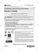
This illustration shows an example of installation.
The exact installation configuration may be slightly different.
Water Heater
The condensing tankless gas Water Hater discharges condensate.
When heat from the exhaust gas is collected within the secondary Heat Exchanger, condensation occurs
from moisture in the exhaust gas and the resulting water is discharged from the condensate drain pipe
(approximately 2 gallons/h (7.5 L/h) maximum). It is not a water leak. Do not plug or block the drain line as it
must always be allowed to freely flow.
Note : The condensate discharged is acidic with a pH level of approximately 2-3. A condensate neutralizer
may be required by local code prior to disposal.
General Parts
During combustion, white
steam may often be seen.
This is normal.
Indoor Installation Outdoor Installation
Outdoor Vent Cap
1 2
7
3
8
9
4
5
6
1. Intake Pipe
2. Exhaust Pipe
3. Front Cover
4. Water Drain Valve (with
Water Filter)
Inside Water Inlet (See page 29)
5. Pressure Relief Valve
6. Hot Water Valve
7. Water Supply Valve
8. Gas Supply Valve
9. Condensate Drain Pipe
Discharge the condensate.

8
The Remote Controller will emit a tone when a button is pressed.
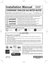
Remote Controller (RC-9018M)
Cover shown in the open position.
General Parts
4
5
10
11
6
7
8
9
Remote Controller
Part Number
The part number is printed
on the surface of the cover.
2
1
3
1. Power Button / Indicator (Green)
For turning the Water Heater ON/OFF.
2. PROG Buon / Indicator (Red)
Activate the automatic Water Heater power ON/
OFF setting as determined by the user selected
schedule. (See page 14)
3. ALARM OFF Button / Indicator (Red)
Stop the tone that is emitted when an error occurs.
(See page 32)
4. Speaker
5. Display Screen (See next page)
6. MENU Button
Use to change system settings or to return to the
home screen.
If you press the MENU button and press the /
buttons, “Sys monitor” is sometimes displayed,
however, do not use this mode as it meant for
installation or service technician only.
7. BACK Button
Return to the previous screen while making system
settings or checking status.
8. / Buttons
For setting the hot water temperature (See page
13), the flow meter alarm, and other settings.
9. ENTER Button
Confirm changes made by the user.
10. STATUS Button
Check the status of the system or the number of
installed the Water Heater. (See page 20)
11. Lock Button
Lock Remote Controller operation. (See page 16)

9
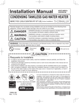
Display Screen
• The display screen shown below is for illustration purposes only.
The actual display will vary depending on how the Water Heater is being used.
• After a button is pressed, the display will gradually become darker to prevent unnecessary power
consumption by the Remote Controller.
(Home Screen Example)
General Parts
8
4
2, 3
1. Flame Indicator
The flame indicator is displayed during combustion
when using hot water or recirculation functions.
2. Display for Temperature Setting
During normal operation, “Temp” is displayed.
3. Display for High Temperature “Hi temp”
Displays when the set temperature is 125°F / 55°C
or higher. (See page 13)
4. Temperature Setting (e.g. 110°F)
5. Clock Display (e.g. 10:15 am)
Normally the clock display is not shown when the
Power button is OFF.
* This setting can be changed so that the clock is
displayed even when the Power button is turned
OFF. (See page 17)
6. Error Code
A number will flash if a failure occurs.
7. Locked Display
The lock symbol is displayed when the Remote
Controller is locked. (See page 16)
8. Recirculation Timer
The clock symbol is displayed when the
recirculation timer is activated. (See page 23)
9. Display for Recirculaon Operaon
• For systems that use recirculation operation, the
symbol is displayed when the Power button is
turned ON.
• It is displayed during the recirculation operation.
(See page 12)
1 7
5, 6 9
NOTE As shipped from the factory, the
Remote Controller is set to display in
°F and gallons.
To adjust the display to °C and liters,
refer to the Installation Manual.
What is the home screen?
The home screen is displayed when the Power button is ON.
Normally, the hot water temperature and the clock, etc. are displayed.

10
Before the first use, do the following:
Initial Operation
Initial Operation
Do not touch the power cord with wet
hands.
WARNING
1. Open the water supply valve.
CLOSED OPEN
2. Open a hot water fixture/faucet to confirm
that water is available, and then close the
fixture/faucet again.
Hot water
fixture/faucet
3. Open the gas supply valve.
4. Turn on the power.

11
• The time changes in 1 minute increments
with each press of the button, and then in 10
minutes increments if the button is pressed
and held.
• If the display is left untouched for
approximately 20 seconds without pressing
the ENTER button, the setting will be
completed. When the Power button is turned
ON, the home screen will be restored.
3. Use the / buttons to reset the clock.
4. Press the the ENTER button to complete the
clock setting.
2. Press the ENTER button.
1. Press the MENU button inside the cover.
(e.g. 10:15 am)
The screen returns to the previous screen.
Clock Adjustment
Clock Adjustment
• This adjustment can be made whether the
Power button is ON/OFF.
NOTE • In the event of a power outage
or after disconnecting power to
the Water Heater, when power is
restored, the clock on the display
screen will show “ - : - - ” and the
clock will need to be reset.
• By default, when the Power button
is turned OFF, the clock display
disappears, but it is possible to
display the clock when the Power
button is turned OFF by changing a
setting. (See page 17)
Operation

12
(e.g. 110°F)
If “System [ Tank ]” is displayed, hot water will be
discharged at the temperature of the storage tank.
(See page 20)
2. Turn on hot water.
1. The Power button is ON.
Using the Water Heater
For systems with recirculation
operation,
is displayed here.
Displayed during combustion
Check
• To prevent scalding :
Hot Water Heater temperatures over 125°F
(52°C) can cause severe burns instantly or
death from scalding.
• Children, disabled and elderly are at the
highest risk of being scalded. Feel water
temperature before bathing or showering.
Temperature limiting valves are available,
consult with installer.
• When setting the Water Heater to 125°F
(55°C in °C mode) or higher, “Hi temp” will
blink for 10 seconds and emit a tone as a high
temperature warning.
• Take caution when using the Water Heater
again after setting to 125°F (52°C) or higher.
Always check the set temperature before use.
• Do not allow anyone to change the water
temperature while hot water is running.
DANGER
Operation
• The Power indicator is displayed.
• The previously set hot water supply
temperature is shown.
• The setting temperature displayed may vary
from the actual temperature at the fixture
depending on conditions such as season or
length of piping.
[For systems with recirculation operation]
• If you set the Power button to ON,
recirculation operation is automatically
started. (If “Synchro ON/OFF” was set to ON.
(See page 21))
• Turn off hot water, the symbol disappears.
• During recirculation, the symbol may be
continuously displayed.
Using the Water Heater

13
Temperature Setting Options
* Display when high temp is set
The temperature settings below are examples.
The temperature setting necessary depends on the usage,
the length of piping and the season.
[When using °F mode] (Default setting is 110°F)
[When using °C mode] (Default setting is 40°C (104°F))
(e.g. 110°F)
If “System [ Tank ]” is displayed, hot water will be
discharged at the temperature of the storage tank.
(See page 20)
(e.g. 105°F)
1. The Power button is ON.
Setting Hot Water Temperature
2. Set the temperature using the / buttons
inside the cover.
100°F Washing dishes, etc.
105°F
Shower, hot water supply, etc.
110°F
115°F
120°F
125°F
High temperature*
(The maximum output temperature
can be set using the remote
contoroller. (See page 17))
130°F
135°F
140°F
145°F
150°F
160°F
170°F
185°F
37°C (99°F) Washing dishes, etc.
38°C (100°F)
39°C (102°F)
Shower, hot water supply, etc.
40°C (104°F)
41°C (106°F)
42°C (108°F)
43°C (109°F)
44°C (111°F)
45°C (113°F)
46°C (115°F)
47°C (117°F)
48°C (118°F)
50°C (122°F)
55°C (131°F)
High temperature*
(The maximum output temperature
can be set using the remote
contoroller. (See page 17))
60°C (140°F)
65°C (149°F)
70°C (158°F)
75°C (167°F)
80°C (176°F)
85°C (185°F)
Operation
• The Power indicator is displayed.
• The previously set hot water supply
temperature is shown.
NOTE • Hot water temperatures shown
are approximate and may differ
from the actual temperature at
the fixture depending on external
factors such as the season and
length of piping in the system.
• When low temperatures are set
(for washing dishes, etc.), if the
incoming water temperature
is already quite high, it may be
difficult to ensure the outgoing
water temperature is as per the
setting.
• Check the temperature displayed
before using any hot water.
Be especially careful using hot
water after the set temperature
has been changed.
• When the hot water temperature
is adjusted using thermostatic
water mixing valves, set the
temperature on the Remote
Controller approximately 20°F
(10°C) higher than the required
temperature to ensure the
appropriate fixture temperature.
NOTE • If the set temperature requires
frequent adjustment, locate the
Remote Controller in an easily
accessible location.
• Consult local codes for minimum
operating temperatures.
• Noritz recommends that water
temperature is set as low as
possible to prevent scale build-up
in the heat exchanger.
(e.g. 125°F)
Blinks for approximately
10 seconds Displayed
Setting Hot Water Temperature

14
This example describes setting the “ON time” and
“OFF time” to 10:00 am and 8:00 pm, respectively.
(Display Example)
Set the time to turn ON or OFF the
Power button automatically
• If you set the time to turn ON or OFF the Power
button, the Power button is automatically turned
ON or OFF at the set time every day by just
turning the PROG button ON.
• It is also possible to set only ON or OFF operation.
• For recirculation systems, circulation is started
or stopped according to the Power button
condition, ON or OFF.
4. Press the ENTER button.
6. Press the ENTER button to complete the setting.
8. Press the ENTER button to complete the setting.
9. Check “Set” is selected, and then press the
ENTER button to confirm all settings.
The PROG button is ON.
5. Set the ON time to “AM 10:00” using the /
buttons.
7. Set the OFF time to “PM 8:00” using the /
buttons.
1. Check that the current time is properly set.
(Setting the time : See page 11)
2. Check the PROG button is set to OFF.
3. Press the MENU button inside the cover, Select
“Set PROG” using the / buttons.
Operation
• The previously set “Start time”and “End time”
are displayed.
• This adjustment can be made whether the
Power button is ON/OFF.
• The time changes in 10 minutes increments
with each press of the button, and then in 1
hour increments if the button is pressed and
held.
• If you do not want to set the “Start time”,
select “- : --” (located between AM 11:50 and
PM 0:00 settings).
• Follow the same procedure from step 5.
• If the display is left untouched for
approximately 20 seconds without pressing
the ENTER button, the setting will be
completed. When the Power button is turned
ON, the home screen will be restored.
• If you want to change “ON/OFF time”, select
“Reset” and then press the ENTER button,
return to step 5.
• You can activate automatic operation
regardless if the Power button is ON or OFF.
• The PROG indicator is displayed when
activated.
• “Start time” and “End time” will be displayed
upon activation.
• If both the “Start time” and “End time” are set
to “- : --”, the alarm sounds and “Set PROG” will
display.
Automatic Water Heater ON or OFF Operation
Activate Automatic Operation
Automatic Water Heater ON or OFF Operation

15
The PROG button is OFF. Following this procedure allows for automated
control of Water Heater operation without user
interaction.
(The setting time shown on the display of the
Remote Controller is for example purposes only.)
• The PROG indicator disappears.
Deactivate Automatic Operation Tips for operation
NOTE • If the PROG button is not set
to OFF, the Water Heater will
automatically turn ON or OFF at
the set times.
• If there is a power failure or power
is disconnected to the Water
Heater, automatic operation will
be deactivated.
e.g. Both ON and OFF functions are automated.
e.g. Only ON function is automated.
e.g. Only OFF function is automated.
The Power buon
is automacally
turned ON
at 10:00 am.
The Power buon
is automacally
turned OFF
at 8:00 pm.
The Power buon
is automacally
turned ON
at 10:00 am.
Your desired me
(Manually
turned OFF)
Your desired me
(Manually
turned ON)
The Power buon
is automacally
turned OFF
at 8:00 pm.
Automatic Water Heater ON or OFF Operation

16
By locking the Remote Controller, the settings
cannot be changed if a button is pressed by mistake.
2. If you press PROG button, MENU button, and
/ buttons while the Remote Controller is
locked, the “Locked” screen will appear.
1. Press and hold Lock button for approximately 2
seconds to lock the Remote Controller.
Press and hold Lock button for approximately 2
seconds to unlock the Remote Controller.
Operation
• This adjustment can be made whether the
Power button is ON/OFF.
• The operations of PROG button, MENU
button, and / buttons are locked.
• Approximately 3 seconds after locking the
Remote Controller, the display will return to
the previous screen.
• Approximately 3 seconds after the “locked”
screen appears, the display will return to the
previous screen.
• Approximately 3 seconds after unlocking the
Remote Controller, the display will return to
the previous screen.
Locking the Remote Controller
Unlock the Remote Controller
Locking the Remote Controller

17
Limiting the Maximum Output
Temperature
The maximum output
temperature can be limited to
prevent discharging hot water at
too high of a temperature.
Display Screen Power Saving
Mode [powersave dsply]
To conserve power consumption
of the display, the screen can be
turned off completely or set to
only display the clock when the
Power button is turned OFF.
Adjusting the brightness of
the display screen when the
Remote Controller is turned on
The display screen can be
brightened, darkened, or the
backlight can be turned off
completely.
1. The Power button is OFF.
2. Press the MENU button
inside the cover, select
“Misc settings” using the
/ buttons.
1. Press the MENU button
inside the cover, select
“Misc settings” using the
/ buttons.
1. Press the MENU button
inside the cover, Select
“Misc settings” using the
/ buttons.
4. Select “Max set temp” using
the / buttons, and then
press the ENTER button.
3. Select “Powersave dsply”
using the / buttons,
and then press the ENTER
button.
3. Select “Brightness” using
the / buttons, and then
press the ENTER button.
5. Change the setting using the
/ buttons.
(Setting completed.)
4. Change the setting using the
/ buttons.
(Setting completed.)
4. Change the setting using the
/ buttons.
(Setting completed.)
Operation Operation Operation
Customizable Settings
Customizable Settings
• The “Misc settings” screen
appears.
• The “Misc settings” screen
appears.
• The “Misc settings” screen
appears.
• To change other settings,
select the option and press
the ENTER button.
• To return to the home screen,
press the MENU button or
let it sit for approximately 20
seconds.
• To change other settings,
select the option and press
the ENTER button.
• To return to the home screen,
press the MENU button or
let it sit for approximately 20
seconds.
• To change other settings,
select the option and press
the ENTER button.
• To return to the home screen,
press the MENU button or
let it sit for approximately 20
seconds.
3. Press the ENTER button.
2. Press the ENTER button. 2. Press the ENTER button.
(e.g. 120°F) (e.g. No-1)
(e.g. Normal)
(Default setting = 120°F/50°C)
(Default setting = No-1)
(Default setting = Normal)
[For Fahrenheit (°F)]
100 - 150°F (In 5°F intervals),
160°F, 170°F, 185°F
[For Celsius (°C)]
37 - 48°C (In 1°C intervals),
50 - 85°C (In 5°C intervals)
Yes : The display will turn
off. The clock will not
be displayed when the
Power button is turned
OFF.
No-1: The display will not turn
off. The clock will not
be displayed when the
Power button is turned
OFF.
No-2: The display will not
turn off. The clock is
displayed when the
Power button is turned
OFF.
Dark / Dim / Normal / Bright

18
Stop draining water
from the Water Heater
Muting the Remote Controller
The Remote Controller can be
muted so that it does not emit a
tone when a button is pressed.
(For Multi-System Only)
Error Tone Settings
The Remote Controller can be
muted so that it does not emit a
tone when an error occurs.
Draining the Water Heater
(Refer to page 26 for details.)
1. Press the MENU button
inside the cover, select
“Misc settings” using the
/ buttons.
1. Press the MENU button
inside the cover, select
“Misc settings” using the
/ buttons.
2. Press the MENU button
inside the cover, select
“Misc settings” using the
/ buttons.
3. Select “Touch sound” using
the / buttons, and then
press the ENTER button.
3. Select “Error alarm” using
the / buttons, and then
press the ENTER button. 4. Select “Drain water” using
the / buttons, and then
press the ENTER button.4. Change the setting using the
/ buttons.
(Setting completed.)
4. Change the setting using the
/ buttons.
(Setting completed.) 5. Select “Yes” using the /
buttons.
Operation Operation Operation
• The “Misc settings” screen
appears.
• To change other settings,
select the option and press
the ENTER button.
• To return to the home screen,
press the MENU button or
let it sit for approximately 20
seconds.
• To change other settings,
select the option and press
the ENTER button.
• To return to the home screen,
press the MENU button or
let it sit for approximately 20
seconds.
• Drain the Water Heater
following the procedures
described on page 26.
2. Press the ENTER button. 2. Press the ENTER button.
3. Press the ENTER button.
6. Press the ENTER button.
If you press the ENTER button
again when “Drain water” and
“Operating” are alternately
displayed following step 6, the
drain function will stop.
(e.g. Yes) (e.g. Yes)
(Default setting = Yes) (Default setting = Yes)
Yes / No Yes / No
1. The Power button is OFF.
Customizable Settings
• The “Misc settings” screen
appears. • The “Misc settings” screen
appears.

19
(Single Water Heater only)
Flow Meter Alarm
The flow meter alarm is being
used to indicate when a tub is
full.
1. The Power button is ON.
2. Press the MENU button
inside the cover, select
“Flow meter” using the
/ buttons.
4. Change the volume using
the / buttons, and then
press the ENTER button.
5. Turn on hot water.
6. Turn off the hot water when
the alarm sounds to prevent
overfilling.
Operation
• Check the current setting
temperature.
• The “Flow meter” screen
appears.
• To return to the home screen,
press the MENU button or
let it sit for approximately 20
seconds.
• When the tub fills with the
preset volume of water, an
alarm will sound alerting you
to shut off the water.
3. Press the ENTER button.
Customizable Settings
(Default setting = Alarm off)
[For gallon]
10 - 60 gal (In 5 gal intervals),
60 - 100 gal (In 10 gal intervals),
Alarm off
[For liter]
40 - 260 L (In 20 L intervals),
260 - 380 L (In 40 L intervals),
Alarm off
NOTE • The hot water filling
temperature is
same as the setting
temperature.
• Although the
temperature
can be set to
125°F/50°C or
higher, do not set
the temperature
to 125°F/50°C or
higher as it can
cause severe burns
instantly or death
from scalding.

20 System Check
System Check
• Depending on the configuration of your system, not all functions may be used.
• If you press the STATUS button, you can check the status of the system.
• The pictures below (the number of Water Heaters, fixtures, and pumps) will vary depending on the
configuration of the hot water system.
(Display Example [System [ Rcrc ] ])
When you start using the system, cold
water in the piping must be discharged
before receiving hot water.
Water Heater
The Water Heater only operation. (Functions other than those shown on pages 21 to 24 can be used.)
Display “System [ Std ]” on the Remote Controller
Instant hot
water is
available.
Hot water is circulated
in the piping.
Pump
Water Heater
• The Water Heater and recirculation operation. (All functions can be used.)
• During recirculation operation, hot water is always circulated in the piping to provide instant hot water when
a fixture is opened. (When setting the recirculation system operation timer, the recirculation system operates
at the set times.)
• If you set the Power button to ON, is displayed. (If “Synchro ON/OFF” is set to ON (See page 21).)
Display “System [ Rcrc ]” on the Remote Controller (For Multi-System only)
Hot Water
storage
tank
Instant hot
water is
available.
Hot water is
circulated to
the tank.
Pump Pump
Water Heater
• The Water Heater combined with a storage tank operation. (Functions other than those shown on pages 21
to 24 can be used.)
• If a recirculation system is also installed, hot water is always circulated in the piping to provide instant hot
water when a fixture is opened.
• If you set the Power button to ON, is displayed.
Display “System [ Tank ]” on the Remote Controller (For Multi-System only)
/