IEI Integration IMBA-R680 User manual
- Category
- Motherboards
- Type
- User manual

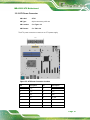
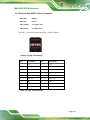
IMBA-R680 ATX Motherboard
Page 1
User Manual
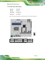
IMBA-R680
ATX motherboard supports LGA1700 12th/13th
Intel® Core® i9/i7/i5/i3, Celeron® and Pentium®
processor, DDR5, Triple Independent Displays,
Dual 2.5GbE LAN, M.2, SATA 6Gb/s and RoHS
MODEL:
Rev. 1.00 – April 27, 2023

IMBA-R680 ATX Motherboard
Page 2
Revision
Date
Version
Changes
April 27, 2023
1.00
Initial release

IMBA-R680 ATX Motherboard
Page 3
Copyright
COPYRIGHT NOTICE
The information in this document is subject to change without prior notice in order to
improve reliability, design and function and does not represent a commitment on the part
of the manufacturer.
In no event will the manufacturer be liable for direct, indirect, special, incidental, or
consequential damages arising out of the use or inability to use the product or
documentation, even if advised of the possibility of such damages.
This document contains proprietary information protected by copyright. All rights are
reserved. No part of this manual may be reproduced by any mechanical, electronic, or other
means in any form without prior written permission of the manufacturer.
TRADEMARKS
All registered trademarks and product names mentioned herein are used for identification
purposes only and may be trademarks and/or registered trademarks of their respective
owners.

IMBA-R680 ATX Motherboard
Page 4
Manual Conventions
WARNING
Warnings appear where overlooked details may cause damage to the
equipment or result in personal injury. Warnings should be taken
seriously.
CAUTION
Cautionary messages should be heeded to help reduce the chance of
losing data or damaging the product.
NOTE
These messages inform the reader of essential but non-critical
information. These messages should be read carefully as any directions
or instructions contained therein can help avoid making mistakes.

IMBA-R680 ATX Motherboard
Page 5
Table of Contents
1 INTRODUCTION ........................................................................................................ 15
1.1 INTRODUCTION ......................................................................................................... 16
1.2 FEATURES ................................................................................................................. 17
1.3 CONNECTORS ........................................................................................................... 18
1.4 DIMENSIONS ............................................................................................................. 19
1.5 DATA FLOW .............................................................................................................. 20
1.6 TECHNICAL SPECIFICATIONS .................................................................................... 21
2 PACKING LIST ........................................................................................................... 23
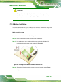
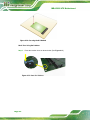
2.1 ANTI-STATIC PRECAUTIONS ...................................................................................... 24
2.2 UNPACKING PRECAUTIONS ....................................................................................... 24
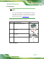
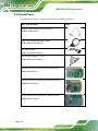
2.3 PACKING LIST .......................................................................................................... 25
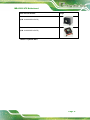
2.4 OPTIONAL ITEMS ...................................................................................................... 26
3 CONNECTORS ........................................................................................................... 28
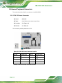
3.1 PERIPHERAL INTERFACE CONNECTORS ..................................................................... 29
3.1.1 IMBA-R680 Layout .......................................................................................... 29
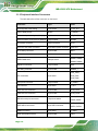
3.1.2 Peripheral Interface Connectors ..................................................................... 30
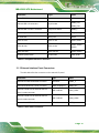
3.1.3 External Interface Panel Connectors ............................................................... 31
3.2 INTERNAL PERIPHERAL CONNECTORS ...................................................................... 32
3.2.1 CPU 12V Power Connector ............................................................................. 32
3.2.2 ATX Power Connector ..................................................................................... 33
3.2.3 Battery Connector ............................................................................................ 34
3.2.4 Chassis Intrusion Connector ............................................................................ 36
3.2.5 AT/ATX Power Mode Setting ........................................................................... 37
3.2.6 Digital I/O Connector ...................................................................................... 38
3.2.7 EC Debug Connector ....................................................................................... 39
3.2.8 Clear CMOS Button ......................................................................................... 40
3.2.9 Flash Descriptor Security Override Jumper .................................................... 41
3.2.10 Fan Connector (CPU) .................................................................................... 42
3.2.11 Fan Connectors (System) ............................................................................... 43

IMBA-R680 ATX Motherboard
Page 6
3.2.12 Audio Connector for iEi AC-KIT-888S kit ..................................................... 44
3.2.13 Front Panel Connector .................................................................................. 45
3.2.14 I2C Connector ................................................................................................ 46
3.2.15 SMBus Connector .......................................................................................... 47
3.2.16 LAN Link LED connector ............................................................................... 48
3.2.17 M.2 M-key Slot ............................................................................................... 49
3.2.18 PCI x1 Slots .................................................................................................... 51
3.2.19 PCIe x4 Slots .................................................................................................. 52
3.2.20 PCIe x16 slots ................................................................................................ 53
3.2.21 Onboard Power Button .................................................................................. 54
3.2.22 DDR5 DIMM sockets ..................................................................................... 55
3.2.23 SATA 6Gb/s Connectors ................................................................................. 56
3.2.24 RS-232 Serial Port Connectors ...................................................................... 57
3.2.25 Flash SPI ROM Connector ............................................................................ 58
3.2.26 Flash EC ROM Connector ............................................................................. 59
3.2.27 Internal USB 2.0 Connectors ......................................................................... 60
3.2.28 Internal USB 3.2 Gen 1 Connector ................................................................ 61
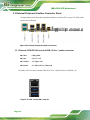
3.3 EXTERNAL PERIPHERAL INTERFACE CONNECTOR PANEL ......................................... 62
3.3.1 External 2.5GbE RJ-45 and dual USB 3.2 Gen 1 combo connector ............... 62
3.3.2 External 2.5GbE RJ-45 and dual USB 3.2 Gen 2 combo connector ............... 63
3.3.3 External Dual USB 3.2 Gen 2 Connector ........................................................ 65
3.3.4 External HDMI And DP Combo Connector .................................................... 66
3.3.5 External RS-232 /422/485 Connector .............................................................. 68
4 INSTALLATION ......................................................................................................... 69
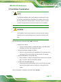
4.1 ANTI-STATIC PRECAUTIONS ...................................................................................... 70
4.2 INTERNAL PERIPHERAL DEVICE CONNECTIONS ........................................................ 70
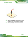
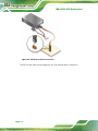
4.2.1 SATA Drive Connection ................................................................................... 70
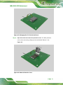
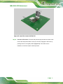
4.3 INSTALLATION CONSIDERATIONS .............................................................................. 73
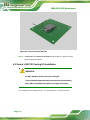
4.4 SOCKET LGA1700 CPU INSTALLATION ................................................................... 74
4.5 SOCKET LGA1700 COOLING KIT INSTALLATION ..................................................... 78
4.6 DIMM INSTALLATION .............................................................................................. 80
4.7 M.2 MODULE INSTALLATION .................................................................................... 81
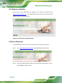
4.8 SOFTWARE INSTALLATION ........................................................................................ 84
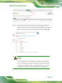
4.9 DRIVER DOWNLOAD ................................................................................................ 84

IMBA-R680 ATX Motherboard
Page 7
5 BIOS .............................................................................................................................. 86
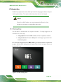
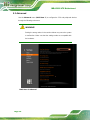
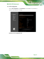
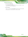
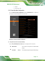
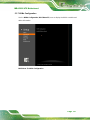
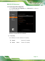
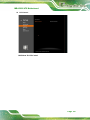
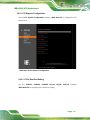
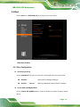
5.1 INTRODUCTION ......................................................................................................... 87
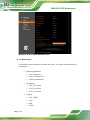
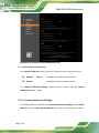
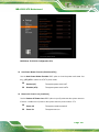
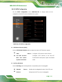
5.1.1 Starting Setup ................................................................................................... 87
5.1.2 Using Setup ...................................................................................................... 88
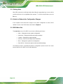
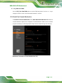
5.1.2.1 Keyboard Navigation ................................................................................ 88
5.1.2.2 Touch Navigation ...................................................................................... 89
5.1.3 Getting Help ..................................................................................................... 90
5.1.4 Unable to Reboot after Configuration Changes .............................................. 90
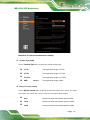
5.1.5 BIOS Menu Bar ................................................................................................ 90
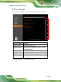
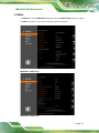
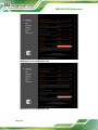
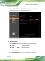
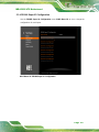
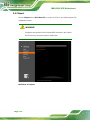
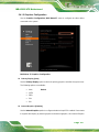
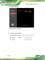
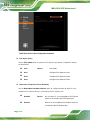
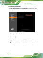
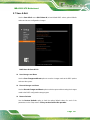
5.2 MAIN ........................................................................................................................ 91
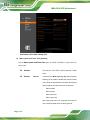
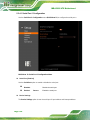
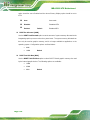
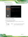
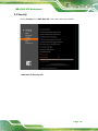
5.3 ADVANCED ............................................................................................................... 94
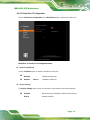
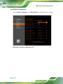
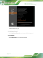
5.3.1 CPU Configuration .......................................................................................... 95
5.3.2 Trusted Computing ......................................................................................... 100
5.3.3 RTC Wake Settings ......................................................................................... 101
5.3.4 F81866 Super IO Configuration .................................................................... 103
5.3.4.1 Serial Port 1 Configuration ..................................................................... 104
5.3.4.2 Serial Port 2 Configuration ..................................................................... 105
5.3.4.3 Serial Port 3 Configuration ..................................................................... 107
5.3.4.4 Serial Port 4 Configuration ..................................................................... 108
5.3.4.5 Serial Port 5 Configuration ..................................................................... 109
5.3.4.6 Serial Port 6 Configuration ...................................................................... 110
5.3.5 EC KB9068 H/W Monitor ............................................................................... 111
5.3.5.1 Smart Fan Mode Configuration ............................................................... 113
5.3.6 Serial Port Console Redirection ..................................................................... 115
5.3.6.1 Console Redirection Settings ................................................................... 116
5.3.7 NVMe Configuration ....................................................................................... 119
5.4 CHIPSET ................................................................................................................. 120
5.4.1 System Agent (SA) Configuration .................................................................. 121
5.4.1.1 Memory Configuration ........................................................................... 122
5.4.1.2 Graphics Configuration ........................................................................... 123
5.4.1.3 VMD Configuration ................................................................................ 126
5.4.1.4 PEG Port Configuration .......................................................................... 127
5.4.2 PCH-IO Configuration .................................................................................. 128
5.4.2.1 PCI Express Configuration ..................................................................... 131

IMBA-R680 ATX Motherboard
Page 8
5.4.2.1.1 PCIe Root Port Setting ....................................................................... 131
5.4.2.2 SATA Configuration ................................................................................ 133
5.4.2.3 HD Audio Configuration ......................................................................... 134
5.5 SECURITY ............................................................................................................... 135
5.6 BOOT ...................................................................................................................... 137
5.6.1 Boot Configuration ........................................................................................ 137
5.6.2 Boot Option Priorities .................................................................................... 138
5.7 SAVE & EXIT .......................................................................................................... 139
A REGULATORY COMPLIANCE ............................................................................ 141
B PRODUCT DISPOSAL ............................................................................................ 143
C BIOS OPTIONS ........................................................................................................ 145
D WATCHDOG TIMER .............................................................................................. 149
E ERROR BEEP CODE ............................................................................................... 152
E.1 PEI BEEP CODES .................................................................................................... 153
E.2 DXE BEEP CODES ................................................................................................. 153
F HAZARDOUS MATERIALS DISCLOSURE ........................................................ 154
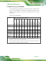
F.1 ROHS II DIRECTIVE (2015/863/EU) ...................................................................... 155
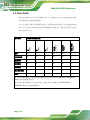
F.2 CHINA ROHS .......................................................................................................... 156

IMBA-R680 ATX Motherboard
Page 9
List of Figures
Figure 1-1: IMBA-R680 .................................................................................................................16
Figure 1-2: Connectors ................................................................................................................18
Figure 1-3: IMBA-R680 Dimensions (mm) ..................................................................................19
Figure 1-4: Data Flow Diagram ....................................................................................................20
Figure 3-1: Peripheral Interface Connectors .............................................................................29
Figure 3-2: CPU 12V Power Connector Location ......................................................................32
Figure 3-3: ATX Power Connector Location ..............................................................................33
Figure 3-4: Battery Connector Location .....................................................................................35
Figure 3-5: Chassis Intrusion Connector Location ...................................................................36
Figure 3-6: AT/ATX Power Mode Switch Locations ..................................................................37
Figure 3-7: Digital I/O Connector Location ................................................................................38
Figure 3-8: EC Debug Connector Location ................................................................................39
Figure 3-9: Clear CMOS Jumper Location .................................................................................40
Figure 3-10: Flash Descriptor Security Override Jumper Location ........................................41
Figure 3-11: CPU Fan Connector Location ................................................................................42
Figure 3-12: System Fan Connector Locations .........................................................................43
Figure 3-13: Audio Connector Location .....................................................................................44
Figure 3-14: Front Panel Connector Location ...........................................................................45
Figure 3-15: I2C Connector Location ..........................................................................................46
Figure 3-16: SMBus Connector Location ...................................................................................47
Figure 3-17: LAN LED Connector Locations .............................................................................48
Figure 3-18: M.2 M-key Slot Location .........................................................................................49
Figure 3-19: PCI x1 Slot Locations .............................................................................................51
Figure 3-20: PCIe x4 Slot Locations ...........................................................................................52
Figure 3-21: PCIe x16 Slot Locations .........................................................................................53
Figure 3-22: Power Button Location ...........................................................................................54
Figure 3-23: DDR5 DIMM Sockets Location ...............................................................................55
Figure 3-24: SATA 6Gb/s Connector Locations ........................................................................56
Figure 3-25: RS-232 Connector Location ...................................................................................57
Figure 3-26: Flash SPI ROM Connector Location .....................................................................58
Figure 3-27: Flash EC ROM Connector Location ......................................................................59

IMBA-R680 ATX Motherboard
Page 10
Figure 3-28: Internal USB 2.0 Connector Locations .................................................................60
Figure 3-29: Internal USB 3.2 Gen 1 Connector Location ........................................................61
Figure 3-30: External Peripheral Interface Connector ..............................................................62
Figure 3-31: USB 3.2 and LAN Connector ..................................................................................62
Figure 3-32: USB 3.2 Connector ..................................................................................................64
Figure 3-33: USB 3.2 Connector ..................................................................................................65
Figure 3-34: HDMI Connector ......................................................................................................66
Figure 3-35: DP++ Connector ......................................................................................................67
Figure 4-1: SATA Drive Cable Connection .................................................................................71
Figure 4-2: SATA Power Drive Connection ................................................................................72
Figure 4-3: Disengage the CPU Socket Load Lever ..................................................................75
Figure 4-4: Remove Protective Cover.........................................................................................75
Figure 4-5: Insert The Socket LGA1200 CPU .............................................................................77
Figure 4-6: Close the Socket LGA1200.......................................................................................78
Figure 4-7: Cooling Kit Support Bracket ....................................................................................79
Figure 4-8: DIMM Installation .......................................................................................................80
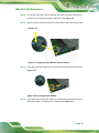
Figure 4-9: Inserting the M.2 Module into the Slot at an Angle................................................81
Figure 4-10: Securing the M.2 Module ........................................................................................82
Figure 4-11: Press the Retainer ...................................................................................................82
Figure 4-12: Aligning the M.2 Module with the Retainer...........................................................83
Figure 4-13: Securing the M.2 Module ........................................................................................83
Figure 4-14: IEI Resource Download Center ..............................................................................84
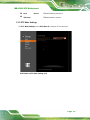
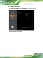
Figure 5-1: BIOS Starting Menu ..................................................................................................87

IMBA-R680 ATX Motherboard
Page 11
List of Tables
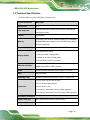
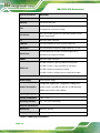
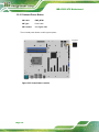
Table 1-1: IMBA-R680 Specifications .........................................................................................22
Table 2-1: Packing List .................................................................................................................25
Table 2-2: Optional Items .............................................................................................................27
Table 3-1: Peripheral Interface Connectors ...............................................................................31
Table 3-2: Rear Panel Connectors ..............................................................................................31
Table 3-3: CPU 12V Power Connector Pinouts ..........................................................................32
Table 3-4: ATX Power Connector Pinouts..................................................................................34
Table 3-5: Battery Connector Pinouts ........................................................................................35
Table 3-6: Chassis Intrusion Connector Pinouts ......................................................................36
Table 3-7: AT/ATX Power Mode Switch Settings .......................................................................37
Table 3-8: Digital I/O Connector Pinouts ....................................................................................38
Table 3-9: EC Debug Connector Pinouts ...................................................................................39
Table 3-10: Clear CMOS Jumper Pinouts ...................................................................................40
Table 3-11: Flash Descriptor Security Override Jumper Pinouts ............................................41
Table 3-12: CPU Fan Connector Pinouts....................................................................................42
Table 3-13: System Fan Connector Pinouts ..............................................................................43
Table 3-14: Audio Connector Pinouts ........................................................................................44
Table 3-15: Front Panel Connector Pinouts ...............................................................................45
Table 3-16: I²C Connector Pinouts ..............................................................................................46
Table 3-17: SMBus Connector Pinouts ......................................................................................47
Table 3-18: LAN1 LED Connector (JLAN_LED1) Pinouts .........................................................48
Table 3-19: LAN2 LED Connector (JLAN_LED 2) Pinouts ........................................................49
Table 3-20: M.2 M-key Connector Pinouts .................................................................................51
Table 3-21: SATA 6Gb/s Connector Pinouts ..............................................................................56
Table 3-22: RS-232 Connector Pinouts ......................................................................................57
Table 3-23: Flash SPI ROM Connector Pinouts .........................................................................58
Table 3-24: Flash EC ROM Connector Pinouts ..........................................................................59
Table 3-25: Internal USB 2.0 Connector Pinouts .......................................................................60
Table 3-26: Internal USB 3.2 Gen 1 Connector Pinouts ............................................................61
Table 3-27: USB 3.2 Port Pinouts ................................................................................................63
Table 3-28: RJ45 Pinouts .............................................................................................................63

IMBA-R680 ATX Motherboard
Page 12
Table 3-29: USB 3.2 Port Pinouts ................................................................................................64
Table 3-30: Dual RJ45 Pinouts ....................................................................................................64
Table 3-31: USB 3.2 Port Pinouts ................................................................................................65
Table 3-32: HDMI Connector Pinouts .........................................................................................66
Table 3-33: DP++ Connector Pinouts .........................................................................................67
Table 3-34: External RS-232/422/485 Connector Pinouts .........................................................68
Table 3-35: DB-9 RS-232/422/485 Pinouts ..................................................................................68
Table 5-1: BIOS Navigation Keys ................................................................................................88
Table 5-2: BIOS On-screen Navigation Keys .............................................................................89

IMBA-R680 ATX Motherboard
Page 13
BIOS Menus
BIOS Menu 1: Main (1/2) ...............................................................................................................91
BIOS Menu 2: Main (2/2) ...............................................................................................................91
BIOS Menu 3: Advanced ..............................................................................................................94
BIOS Menu 4: CPU Configuration (1/3).......................................................................................95
BIOS Menu 5: CPU Configuration (2/3).......................................................................................96
BIOS Menu 6: CPU Configuration (3/3).......................................................................................96
BIOS Menu 7: PCH-FW Configuration ......................................................................................100
BIOS Menu 8: RTC Wake Settings (1/2) ....................................................................................101
BIOS Menu 9: RTC Wake Settings (2/2) ....................................................................................102
BIOS Menu 10: F81866 Super IO Configuration ......................................................................103
BIOS Menu 11: Serial Port 1 Configuration Menu ...................................................................104
BIOS Menu 12: Serial Port 2 Configuration Menu ...................................................................105
BIOS Menu 13: Serial Port 3 Configuration Menu ...................................................................107
BIOS Menu 14: Serial Port 4 Configuration Menu ...................................................................108
BIOS Menu 15: Serial Port 5 Configuration Menu ...................................................................109
BIOS Menu 16: Serial Port 6 Configuration Menu ...................................................................110
BIOS Menu 17: EC KB9068 H/W Monitor (1/2) .........................................................................111
BIOS Menu 18: EC KB9068 H/W Monitor (2/2) .........................................................................112
BIOS Menu 19: Smart Fan Mode Configuration ......................................................................113
BIOS Menu 20: Serial Port Console Redirection (1/2) .............................................................115
BIOS Menu 21: Serial Port Console Redirection (2/2) .............................................................116
BIOS Menu 22: COM Console Redirection Settings ...............................................................117
BIOS Menu 23: NVMe Configuration .........................................................................................119
BIOS Menu 24: Chipset ..............................................................................................................120
BIOS Menu 25: System Agent (SA) Configuration ..................................................................121
BIOS Menu 26: Memory Configuration .....................................................................................122
BIOS Menu 27: Graphics Configuration ...................................................................................123
BIOS Menu 28: LCD Control ......................................................................................................125
BIOS Menu 29: VMD Configuration ...........................................................................................126
BIOS Menu 30: PEG Port Configuration ...................................................................................127
BIOS Menu 31: PCH-IO Configuration (1/2) .............................................................................128

IMBA-R680 ATX Motherboard
Page 14
BIOS Menu 32: PCH-IO Configuration (2/2) .............................................................................129
BIOS Menu 33: PCI Express Configuration .............................................................................131
BIOS Menu 34: PCIe Slot Configuration Submenu .................................................................132
BIOS Menu 35: SATA Configuration .........................................................................................133
BIOS Menu 36: HD Audio Configuration ..................................................................................134
BIOS Menu 37: Security (1/2) .....................................................................................................135
BIOS Menu 38: Security (2/2) .....................................................................................................136
BIOS Menu 39: Boot ...................................................................................................................137
BIOS Menu 40: Save & Exit ........................................................................................................139

IMBA-R680 ATX Motherboard
Page 15
Chapter
1
1 Introduction

IMBA-R680 ATX Motherboard
Page 16
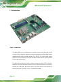
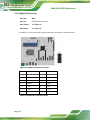
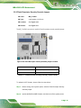
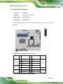
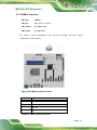
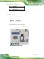
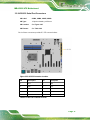
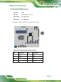
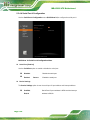
1.1 Introduction
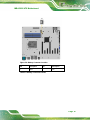
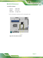
Figure 1-1: IMBA-R680
The IMBA-R680 is an ATX motherboard. It accepts a Socket LGA1700 Intel® 12/13th
Core® i9/i7/i5/i3, Pentium® or Celeron® processor and supports four 288-pin dual-channel
unbuffered DDR5 SDRAM DIMM modules up to 128 GB. The Intel® R680E chipset
supports four SATA 6Gb/s drives. Moreover, the IMBA-R680 includes DP, HDMI and iDPM
for triple independent display.
The IMBA-R680 provides two 2.5GbE interfaces through the Intel® I225V controllers.
Expansion and I/O include two PCIe slots, two PCIe x16 slot, three PCIe x4 slots, two
M.2 slots, six COM ports, two USB 3.2 Gen 1, four USB 3.2 Gen 2, four USB 3.2 via
internal pin headers, two USB 3.2 Gen 1 via internal box header.

IMBA-R680 ATX Motherboard
Page 17
1.2 Features
Some of the IMBA-R680 motherboard features are listed below:
▪ ATX form factor
▪ LGA1700 12th/13th Generation Intel® Core® i9/i7/i5/i3, Celeron® and
Pentium® processors (up to 125W TDP) Intel® R680E chipset
▪ Four 288-pin dual-channel unbuffered DDR5 (up to 4400 MHz) SDRAM DIMM
slots supporting up to 128 GB memory (ECC & non-ECC supported)
▪ Two Intel® I225V 2.5GbE controller
▪ Triple independent display by DP, HDMI and iDPM eDP/ LVDS/ VGA module
▪ Four SATA 6Gb/s connectors support RAID 0, 1, 5, 10
▪ Two USB 3.2 Gen 1 ports and four USB 3.2 Gen 2 ports
▪ One M.2 M-key slot for SSD; one M.2 M-key slot with PCIe x4 signal
▪ 2 x PCIe Gen5 x16 slot with x8 signal
▪ 3 x PCIe Gen4 x4 open-end slot
▪ 2 x PCIe Gen3 x1 slot
▪ Six serial ports (two on panel,the others via internal pin header)
▪ TPM 2.0 security function supported by PTT
▪ RoHS compliant

IMBA-R680 ATX Motherboard
Page 18
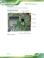
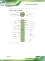
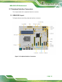
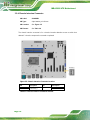
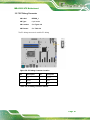
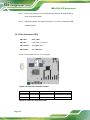
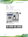
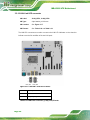
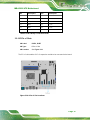
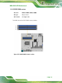
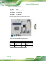
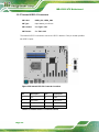
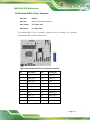
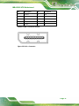
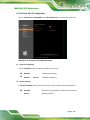
1.3 Connectors
The connectors on the IMBA-R680 are shown in the figure below.
Figure 1-2: Connectors

IMBA-R680 ATX Motherboard
Page 19
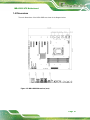
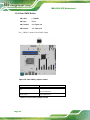
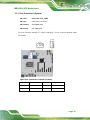
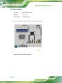
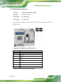
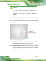
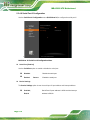
1.4 Dimensions
The main dimensions of the IMBA-R680 are shown in the diagram below.
Figure 1-3: IMBA-R680 Dimensions (mm)

Page is loading ...
Page is loading ...
Page is loading ...
Page is loading ...
Page is loading ...
Page is loading ...
Page is loading ...
Page is loading ...
Page is loading ...
Page is loading ...
Page is loading ...
Page is loading ...
Page is loading ...
Page is loading ...
Page is loading ...
Page is loading ...
Page is loading ...
Page is loading ...
Page is loading ...
Page is loading ...
Page is loading ...
Page is loading ...
Page is loading ...
Page is loading ...
Page is loading ...
Page is loading ...
Page is loading ...
Page is loading ...
Page is loading ...
Page is loading ...
Page is loading ...
Page is loading ...
Page is loading ...
Page is loading ...
Page is loading ...
Page is loading ...
Page is loading ...
Page is loading ...
Page is loading ...
Page is loading ...
Page is loading ...
Page is loading ...
Page is loading ...
Page is loading ...
Page is loading ...
Page is loading ...
Page is loading ...
Page is loading ...
Page is loading ...
Page is loading ...
Page is loading ...
Page is loading ...
Page is loading ...
Page is loading ...
Page is loading ...
Page is loading ...
Page is loading ...
Page is loading ...
Page is loading ...
Page is loading ...
Page is loading ...
Page is loading ...
Page is loading ...
Page is loading ...
Page is loading ...
Page is loading ...
Page is loading ...
Page is loading ...
Page is loading ...
Page is loading ...
Page is loading ...
Page is loading ...
Page is loading ...
Page is loading ...
Page is loading ...
Page is loading ...
Page is loading ...
Page is loading ...
Page is loading ...
Page is loading ...
Page is loading ...
Page is loading ...
Page is loading ...
Page is loading ...
Page is loading ...
Page is loading ...
Page is loading ...
Page is loading ...
Page is loading ...
Page is loading ...
Page is loading ...
Page is loading ...
Page is loading ...
Page is loading ...
Page is loading ...
Page is loading ...
Page is loading ...
Page is loading ...
Page is loading ...
Page is loading ...
Page is loading ...
Page is loading ...
Page is loading ...
Page is loading ...
Page is loading ...
Page is loading ...
Page is loading ...
Page is loading ...
Page is loading ...
Page is loading ...
Page is loading ...
Page is loading ...
Page is loading ...
Page is loading ...
Page is loading ...
Page is loading ...
Page is loading ...
Page is loading ...
Page is loading ...
Page is loading ...
Page is loading ...
Page is loading ...
Page is loading ...
Page is loading ...
Page is loading ...
Page is loading ...
Page is loading ...
Page is loading ...
Page is loading ...
Page is loading ...
Page is loading ...
Page is loading ...
Page is loading ...
Page is loading ...
Page is loading ...
Page is loading ...
-
 1
1
-
 2
2
-
 3
3
-
 4
4
-
 5
5
-
 6
6
-
 7
7
-
 8
8
-
 9
9
-
 10
10
-
 11
11
-
 12
12
-
 13
13
-
 14
14
-
 15
15
-
 16
16
-
 17
17
-
 18
18
-
 19
19
-
 20
20
-
 21
21
-
 22
22
-
 23
23
-
 24
24
-
 25
25
-
 26
26
-
 27
27
-
 28
28
-
 29
29
-
 30
30
-
 31
31
-
 32
32
-
 33
33
-
 34
34
-
 35
35
-
 36
36
-
 37
37
-
 38
38
-
 39
39
-
 40
40
-
 41
41
-
 42
42
-
 43
43
-
 44
44
-
 45
45
-
 46
46
-
 47
47
-
 48
48
-
 49
49
-
 50
50
-
 51
51
-
 52
52
-
 53
53
-
 54
54
-
 55
55
-
 56
56
-
 57
57
-
 58
58
-
 59
59
-
 60
60
-
 61
61
-
 62
62
-
 63
63
-
 64
64
-
 65
65
-
 66
66
-
 67
67
-
 68
68
-
 69
69
-
 70
70
-
 71
71
-
 72
72
-
 73
73
-
 74
74
-
 75
75
-
 76
76
-
 77
77
-
 78
78
-
 79
79
-
 80
80
-
 81
81
-
 82
82
-
 83
83
-
 84
84
-
 85
85
-
 86
86
-
 87
87
-
 88
88
-
 89
89
-
 90
90
-
 91
91
-
 92
92
-
 93
93
-
 94
94
-
 95
95
-
 96
96
-
 97
97
-
 98
98
-
 99
99
-
 100
100
-
 101
101
-
 102
102
-
 103
103
-
 104
104
-
 105
105
-
 106
106
-
 107
107
-
 108
108
-
 109
109
-
 110
110
-
 111
111
-
 112
112
-
 113
113
-
 114
114
-
 115
115
-
 116
116
-
 117
117
-
 118
118
-
 119
119
-
 120
120
-
 121
121
-
 122
122
-
 123
123
-
 124
124
-
 125
125
-
 126
126
-
 127
127
-
 128
128
-
 129
129
-
 130
130
-
 131
131
-
 132
132
-
 133
133
-
 134
134
-
 135
135
-
 136
136
-
 137
137
-
 138
138
-
 139
139
-
 140
140
-
 141
141
-
 142
142
-
 143
143
-
 144
144
-
 145
145
-
 146
146
-
 147
147
-
 148
148
-
 149
149
-
 150
150
-
 151
151
-
 152
152
-
 153
153
-
 154
154
-
 155
155
-
 156
156


IEI Integration IMBA-R680 User manual
- Category
- Motherboards
- Type
- User manual
Ask a question and I''ll find the answer in the document
Finding information in a document is now easier with AI