OM-271 973 Page 1
SECTION 1 − SAFETY PRECAUTIONS − READ BEFORE USING
ihom _2013-09
Protect yourself and others from injury — read, follow, and save these important safety precautions and operating instructions.
1-1. Symbol Usage
DANGER! − Indicates a hazardous situation which, if
not avoided, will result in death or serious injury. The
possible hazards are shown in the adjoining symbols
or explained in the text.
Indicates a hazardous situation which, if not avoided,
could result in death or serious injury. The possible
hazards are shown in the adjoining symbols or ex-
plained in the text.
NOTICE − Indicates statements not related to personal injury.
. Indicates special instructions.
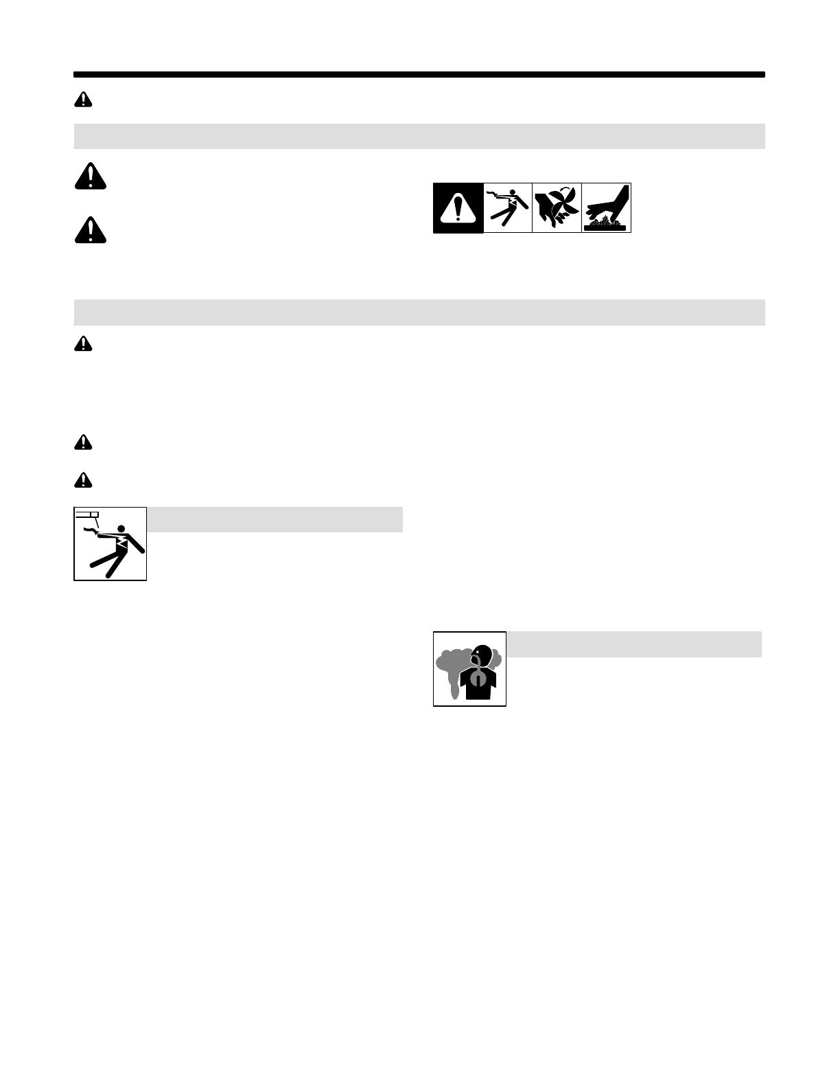
This group of symbols means Warning! Watch Out! ELECTRIC
SHOCK, MOVING PARTS, and HOT PARTS hazards. Consult sym-
bols and related instructions below for necessary actions to avoid the
hazards.
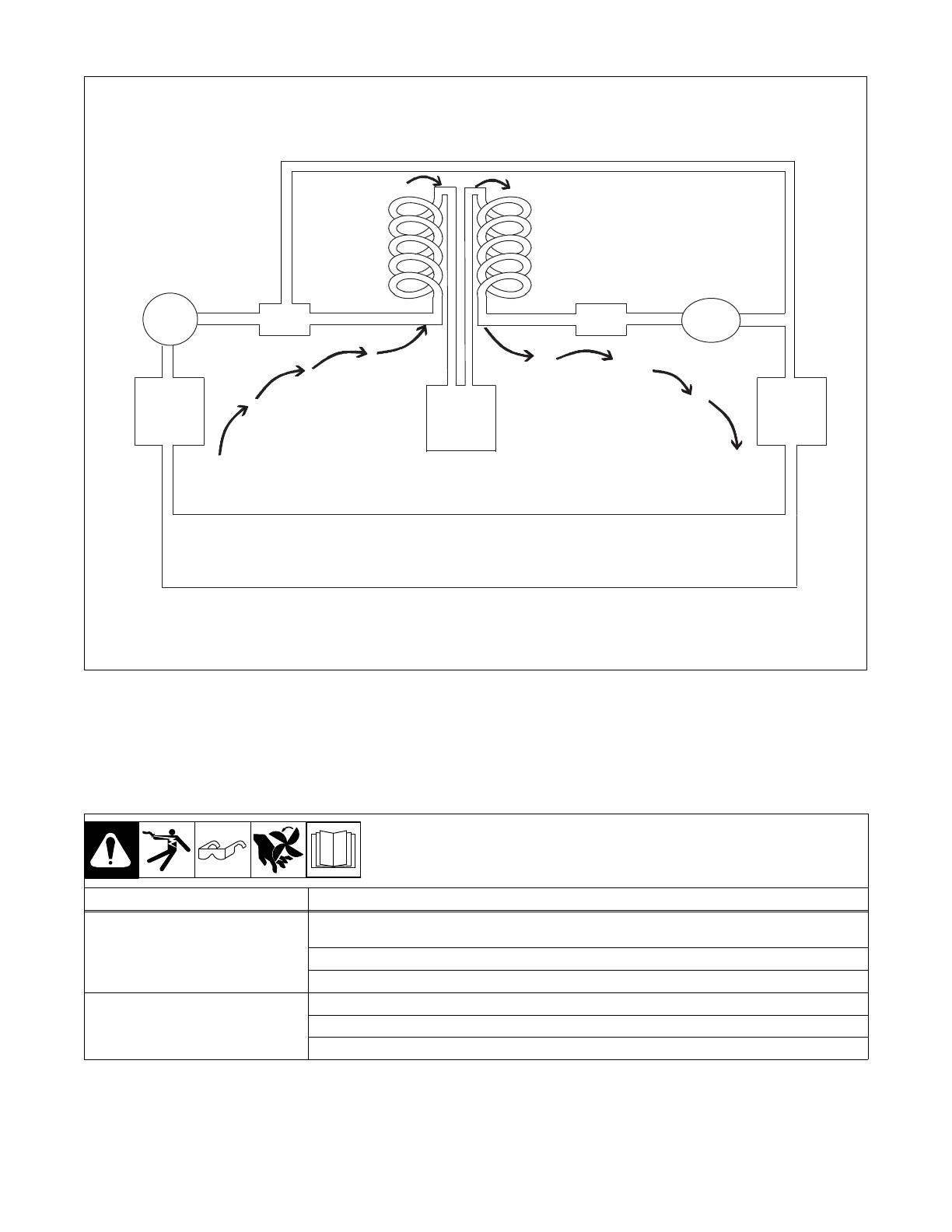
1-2. Induction Heating Hazards
The symbols shown below are used throughout this manual
to call attention to and identify possible hazards. When you
see the symbol, watch out, and follow the related instructions
to avoid the hazard. The safety information given below is
only a summary of the more complete safety information
found in the Safety Standards listed in Section 1-5. Read and
follow all Safety Standards.
Only qualified persons should install, operate, maintain, and
repair this unit.
During operation, keep everybody, especially children, away.
ELECTRIC SHOCK can kill.
Touching live electrical parts can cause fatal shocks
or severe burns. The power circuit and output bus
bars or connections are electrically live whenever
the output is on. The input power circuit and machine
internal circuits are also live when power is on. Incorrectly installed or
improperly grounded equipment is a hazard.
D Do not touch live electrical parts.
D Enclose any connecting bus bars and coolant fittings to prevent
unintentional contact.
D Wear dry, hole-free insulating gloves and body protection.
D Insulate yourself from work and ground using dry insulating mats or
covers big enough to prevent any physical contact with the work or
ground.
D Additional safety precautions are required when any of the following
electrically hazardous conditions are present: in damp locations or
while wearing wet clothing; on metal structures such as floors, grat-
ings, or scaffolds; when in cramped positions such as sitting,
kneeling, or lying; or when there is a high risk of unavoidable or acci-
dental contact with the workpiece or ground. For these conditions,
see ANSI Z49.1 listed in Safety Standards. And, do not work alone!
D Disconnect input power before installing or servicing this equip-
ment. Lockout/tagout input power according to OSHA 29 CFR
1910.147 (see Safety Standards).
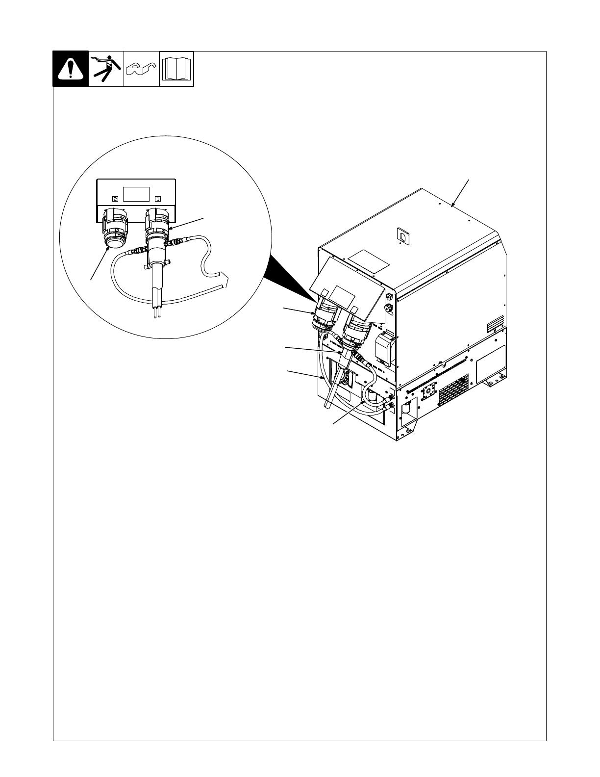
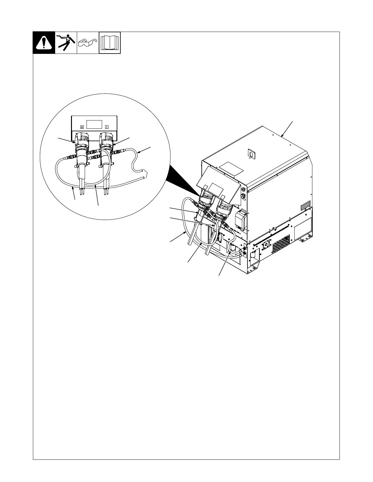
D Use only nonconductive coolant hoses with a minimum length of 18
inches (457 mm) to provide isolation.
D Properly install, ground, and operate this equipment according to its
Owner’s Manual and national, state, and local codes.
D Always verify the supply ground − check and be sure that input pow-
er cord ground wire is properly connected to ground terminal in
disconnect box or that cord plug is connected to a properly grounded
receptacle outlet.
D When making input connections, attach proper grounding
conductor first − double-check connections.
D Keep cords dry, free of oil and grease, and protected from hot metal
and sparks.
D Frequently inspect input power cord and ground conductor for dam-
age or bare wiring – replace immediately if damaged – bare wiring
can kill.
D Turn off all equipment when not in use.
D Do not use worn, damaged, undersized, or repaired cables.
D Do not drape cables over your body.
D Do not touch power circuit if you are in contact with the work, ground,
or another power circuit from a different machine.
D Use only well-maintained equipment. Repair or replace damaged
parts at once. Maintain unit according to manual.
D Wear a safety harness if working above floor level.
D Keep all panels and covers securely in place.
D Use GFCI protection when operating auxiliary equipment in damp or
wet locations.
SIGNIFICANT DC VOLTAGE exists in inverter power
sources AFTER removal of input power.
D Turn Off inverter, disconnect input power, and discharge input
capacitors according to instructions in Maintenance Section before
touching any internal parts.
Induction Heating of certain materials, adhesives,
and fluxes can produce fumes and gases. Breathing
these fumes and gases can be hazardous to your
health.
FUMES AND GASES can be hazardous.
D Keep your head out of the fumes. Do not breathe the fumes.
D If inside, ventilate the area and/or use local forced ventilation to re-
move fumes and gases. The recommended way to determine
adequate ventilation is to sample for the composition and quantity of
fumes and gases to which personnel are exposed.
D If ventilation is poor, wear an approved air-supplied respirator.
D Read and understand the Safety Data Sheets (SDSs) and the man-
ufacturer’s instructions for adhesives, coatings, cleaners,
consumables, coolants, degreasers, fluxes, and metals.
D Work in a confined space only if it is well ventilated, or while wearing
an air-supplied respirator. Always have a trained watchperson near-
by. Fumes and gases from heating can displace air and lower the
oxygen level causing injury or death. Be sure the breathing air is
safe.
D Do not heat in locations near degreasing, cleaning, or spraying oper-
ations. The heat can react with vapors to form highly toxic and
irritating gases.
D Do not overheat coated metals, such as galvanized, lead, or
cadmium plated steel, unless the coating is removed from the
heated area, the area is well ventilated, and while wearing an air-
supplied respirator. The coatings and any metals containing these
elements can give off toxic fumes if overheated. See coating SDS
for temperature information.