Simplicity 030477A-00 User guide
- Category
- Power generators
- Type
- User guide

Not for
Reproduction
BRIGGS & STRATTON CORPORATION
MILWAUKEE, WISCONSIN, U.S.A.
Manual No. 80012134 Revision B
Portable Generator
Operator’s Manual
Generator per PGMA (Portable Generator Manufacturers’ Association) standard ANSI/PGMA G300-2015,
Safety and Performance of Portable Generators.

Not for
Reproduction
2 troybilt.com
Copyright © 2018. Briggs & Stratton Corporation
Milwaukee, WI, USA. All rights reserved.
TROY-BILT is a registered trademark of MTD.
Used under license.
Thank you for purchasing this quality-built Troy-Bilt® generator. We are pleased that you’ve placed your
confidence in the Troy-Bilt brand. When operated and maintained according to the instructions in this manual, your
Troy-Bilt generator will provide many years of dependable service.
This manual contains safety information to make you aware of the hazards and risks associated with generators
and how to avoid them. This generator is designed and intended only for supplying electrical power for operating
compatible electrical lighting, appliances, tools and motor loads, and is not intended for any other purpose. It is
important that you read and understand these instructions thoroughly before attempting to start or operate this
equipment. Save these original instructions for future reference.
This generator requires final assembly before use. Refer to the Assembly section of this manual for
instructions on final assembly procedures. Follow the instructions completely.
Where to Find Us
You never have to look far to find Briggs & Stratton support and service for your generator. Consult your Yellow Pages.
There are over 30,000 Briggs & Stratton authorized service dealers worldwide who provide quality service. You can also
contact Troy-Bilt Customer Service by phone at (888) 611-6708, or on the Internet at www.troybilt.com.
Generator
Model Number _____________________________
Revision __________________________________
Serial Number ______________________________
Date Purchased ___________________________
Engine
Model Number _____________________________
Type Number ______________________________
Code Number ______________________________
Table of Contents
Safe Operation Checklist ...............3
Operator Safety.......................4
Assembly............................9
Features and Controls ................15
Operation...........................20
Maintenance ........................24
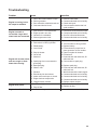
Troubleshooting .....................29
Warranty ...........................30
Product Specications ................32
Common Service Parts ...............32

Not for
Reproduction
3
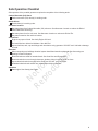
Safe Operation Checklist
Safe operation of the portable generator requires the completion of the following tasks:
Carbon Monoxide (CO) Alarm
Carbon monoxide (CO) alarm(s) in working order.
Smoke Alarm
Smoke alarm(s) in working order.
Generator Location
Generator placed in a Carbon Monoxide (CO) safe zone. See Generator Location to reduce the Risk of
Carbon Monoxide Poisoning.
Generator placed in a fire safe zone. See Generator Location to reduce the Risk of Fire.
Generator located on flat and level surface.
Oil and Fuel
Engine has proper oil level. See Verify Engine Oil Level.
Fuel tank filled at or below fuel indicator. See Add Fuel.
Inspect fuel lines, tank, cap and fittings each time before using generator. DO NOT use if fuel leak or damage
is found.
Electrical
When connecting to a buildings electrical system install listed transfer equipment. See Connecting to a
Building’s Electrical System.
Electrical cords are rated for intended loads. See Cord Sets and Receptacles.
Electrical cords do not run through doorways, windows, holes in ceilings, walls or floors.
Inspect electrical cords thoroughly before each use. DO NOT use if damaged.
All labeled electrical cord safeties are understood and being followed.
Operation
Start engine. See Starting the Engine.

Not for
Reproduction
4 troybilt.com
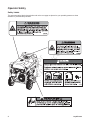
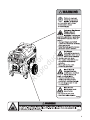
Operator Safety
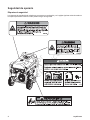
Safety Labels
The generator safety labels shown below and on the next page are placed on your portable generator to draw
attention to potential safety hazards.
202997

Not for
Reproduction
5

Not for
Reproduction
6 troybilt.com
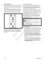
Equipment Description
Read this manual carefully and become
familiar with your generator. Know its
applications, its limitations and any
hazards involved.
The generator is an engine-driven, revolving field,
alternating current (AC) generator equipped with a
voltage regulator. The voltage regulator is designed to
automatically maintain a constant output voltage level.
It was designed to supply electrical power for operating
compatible electrical lighting, appliances, tools and
motor loads. The generator’s revolving field is driven at
about 3600 rpm by a single cylinder engine.
NOTICE
Exceeding generators wattage/amperage
capacity could damage generator and/or electrical
devices connected to it.
• DO NOT exceed the generator’s wattage/amperage
capacity. See Don’t Overload Generator in the Operation
section.
Every effort has been made to ensure that the
information in this manual is both accurate and current.
However, the manufacturer reserves the right to
change, alter or otherwise improve the generator and
this documentation at any time without prior notice.
The Emission Control System for this generator is
warranted for standards set by the Environmental
Protection Agency and the California Air Resources
Board.
Important Safety Information
The manufacturer cannot possibly anticipate every
possible circumstance that might involve a hazard.
The warnings in this manual, and the tags and decals
affixed to the unit are, therefore, not all-inclusive.
If you use a procedure, work method or operating
technique that the manufacturer does not specifically
recommend, you must satisfy yourself that it is safe
for you and others. You must also make sure that the
procedure, work method or operating technique that
you choose does not render the generator unsafe.
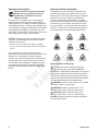
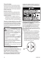
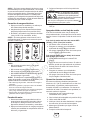
Safety Symbols and Meanings
The safety alert symbol indicates a potential
personal injury hazard. A signal word (DANGER,
WARNING, or CAUTION) is used with the alert symbol
to designate a degree or level of hazard seriousness.
A safety symbol may be used to represent the type of
hazard. The signal word NOTICE indicates information
considered important, but not hazard-related.
DANGER indicates a hazard which, if not avoided,
will result in death or serious injury.
WARNING indicates a hazard which, if not
avoided, could result in death or serious injury.
CAUTION indicates a hazard which, if not
avoided, could result in minor or moderate injury.
NOTICE indicates information considered important
but not hazard-related.
Fire
Explosion
Toxic Fumes
Hot Surface
Moving Parts
Electrical Shock
Kickback
Flying Objects
Operator’s Manual

Not for
Reproduction
7
WARNING
• This generator does not meet U. S. Coast Guard
Regulation 33CFR-183 and should not be used on
marine applications.
• Failure to use the appropriate U. S. Coast Guard
approved generator could result in death or serious injury.
WARNING Fuel and its vapors are extremely
flammable and explosive which
could cause burns, fire or explosion
resulting in death or serious injury.
WHEN ADDING OR DRAINING FUEL
• Turn generator engine OFF and let it cool at least 2
minutes before removing fuel cap. Loosen cap slowly to
relieve pressure in tank.
• Fill or drain fuel tank outdoors.
• DO NOT overfill tank. Allow space for fuel expansion.
• If fuel spills, wait until it evaporates before starting
engine.
• Keep fuel away from sparks, open flames, pilot lights,
heat, and other ignition sources.
• Check fuel lines, tank, cap and fittings frequently for
cracks or leaks. Replace if necessary.
• DO NOT light a cigarette or smoke.
WHEN STARTING EQUIPMENT
• Ensure spark plug, muffler, fuel cap, and air cleaner are
in place.
• DO NOT crank engine with spark plug removed.
WHEN OPERATING EQUIPMENT
• DO NOT operate this product inside any building,
carport, porch, mobile equipment, marine applications,
or enclosure.
• DO NOT tip engine or equipment at angle which causes
fuel to spill.
• DO NOT stop engine by moving choke control to
CHOKE
( ) position.
WHEN TRANSPORTING,
MOVING OR REPAIRING EQUIPMENT
• Transport/move/repair with fuel tank EMPTY or with fuel
shutoff valve OFF.
• DO NOT tip engine or equipment at angle which causes
fuel to spill.
• Disconnect spark plug wire.
STORING FUEL OR EQUIPMENT WITH FUEL IN TANK
• Store away from furnaces, stoves, water heaters, clothes
dryers, or other appliances that have pilot light or other
ignition source because they could ignite fuel vapors.
WARNING Starter cord kickback (rapid
retraction) will pull hand and arm toward
engine faster than you can let go which
could cause broken bones, fractures,
bruises, or sprains resulting in serious injury.
• When starting engine, pull cord slowly until resistance is
felt and then pull rapidly to avoid kickback.
• NEVER start or stop engine with electrical devices
plugged in and turned on.
WARNING POISONOUS GAS HAZARD.
Engine exhaust contains carbon monoxide,
a poisonous gas that could kill you in
minutes. You CANNOT smell it, see it, or
taste it. Even if you do not smell exhaust fumes, you
could still be exposed to carbon monoxide gas.
• Operate this product ONLY outside far away from
windows, doors and vents to reduce the risk of carbon
monoxide gas from accumulating and potentially being
drawn towards occupied spaces.
• Install battery-operated carbon monoxide alarms or
plug-in carbon monoxide alarms with battery back-up
according to the manufacturer’s instructions. Smoke
alarms cannot detect carbon monoxide gas.
• DO NOT run this product inside homes, garages,
basements, crawlspaces, sheds, or other partially-
enclosed spaces even if using fans or opening doors
and windows for ventilation. Carbon monoxide can
quickly build up in these spaces and can linger for hours,
even after this product has shut off.
• ALWAYS place this product downwind and point the
engine exhaust away from occupied spaces.
If you start to feel sick, dizzy, or weak while using this
product, shut it off and get to fresh air RIGHT AWAY. See
a doctor. You may have carbon monoxide poisoning.
WARNING
This product can expose you to
chemicals including gasoline engine exhaust, which is
known to the State of California to cause cancer, and
carbon monoxide, which is known to the State of California
to cause birth defects or other reproductive harm. For more
information go to www.P65Warnings.ca.gov.

Not for
Reproduction
8 troybilt.com
NOTICE
Exceeding generators wattage/amperage
capacity could damage generator and/or electrical
devices connected to it.
• DO NOT exceed the generator’s wattage/amperage
capacity. See Don’t Overload Generator in the Operation
section.
• Start generator and let engine stabilize before connecting
electrical loads.
• Connect electrical loads in OFF position, then turn ON for
operation.
• Turn electrical loads OFF and disconnect from generator
before stopping generator.
NOTICE
Improper treatment of generator could
damage it and shorten its life.
• Use generator only for intended uses.
• If you have questions about intended use, ask dealer or
contact local service center.
• Operate generator only on level surfaces.
• DO NOT expose generator to excessive moisture, dust,
dirt, or corrosive vapors.
• DO NOT insert any objects through cooling slots.
• If connected devices overheat, turn them off and
disconnect them from generator.
• Shut off generator if:
-electrical output is lost;
-equipment sparks, smokes, or emits flames;
-unit vibrates excessively.
WARNING Starter and other rotating parts
could entangle hands, hair, clothing, or
accessories resulting in serious injury.
• NEVER operate generator without protective housing or
covers.
• DO NOT wear loose clothing, jewelry or anything that
could be caught in the starter or other rotating parts.
• Tie up long hair and remove jewelry.
CAUTION Excessively high operating speeds
could result in minor injury.
Excessively low operating speeds impose a heavy
load.
• DO NOT tamper with governor spring, links or other
parts to increase engine speed. Generator supplies
correct rated frequency and voltage when running at
governed speed.
• DO NOT modify generator in any way.
WARNING
Generator voltage could cause
electrical shock or burn resulting in death or
serious injury.
• Use listed transfer equipment, suitable for the intended
use, to prevent backfeed by isolating generator from
electric utility workers.
• When using generator for backup power, notify utility
company.
• Use a ground fault circuit interrupter (GFCI) in any damp
or highly conductive area, such as metal decking or steel
work.
• DO NOT touch bare wires or receptacles.
• DO NOT use generator with electrical cords which are
worn, frayed, bare or otherwise damaged.
• DO NOT operate generator in the rain or wet weather.
• DO NOT handle generator or electrical cords while
standing in water, while barefoot, or while hands or feet
are wet.
• DO NOT allow unqualified persons or children to operate
or service generator.
WARNING Exhaust heat/gases could ignite
combustibles, structures or damage
fuel tank causing a fire, resulting in
death or serious injury.
Contact with muffler area could cause burns
resulting in serious injury.
• DO NOT touch hot parts and AVOID hot exhaust gases.
• Allow equipment to cool before touching.
• Keep at least 5 feet (1.5 m) of clearance on all sides of
generator including overhead.
• It is a violation of California Public Resource Code,
Section 4442, to use or operate the engine on any forest-
covered, brush-covered, or grass-covered land unless
the exhaust system is equipped with a spark arrester, as
defined in Section 4442, maintained in effective working
order. Other states or federal jurisdictions may have
similar laws.
Contact the original equipment manufacturer, retailer,
or dealer to obtain a spark arrester designed for the
exhaust system installed on this engine.
• Replacement parts must be the same and installed in the
same position as the original parts.
WARNING Unintentional sparking could cause
fire or electric shock resulting in
death or serious injury.
WHEN ADJUSTING OR MAKING REPAIRS TO YOUR
GENERATOR
• Disconnect the spark plug wire from the spark plug and
place the wire where it cannot contact spark plug.
WHEN TESTING FOR ENGINE SPARK
• Use approved spark plug tester.
• DO NOT check for spark with spark plug removed.

Not for
Reproduction
9
Assembly
Read entire operator’s manual before you
attempt to assemble or operate your new
generator.
Your generator requires some assembly and is ready
for use after it has been properly serviced with the
recommended fuel and oil level is verified.
If you have any problems with the assembly of
your generator, please call the generator helpline
at (888) 611-6708. If calling for assistance, please
have the model, revision, and serial number from the
identification label available. See generator Features
and Controls for identification label location.
Unpack Generator
1. Set the carton on a rigid, flat surface.
2. Remove everything from carton except generator.
3. Open carton completely by cutting each corner
from top to bottom.
4. Leave generator on carton to install wheel kit.
The generator is supplied with:
• Operator’s manual
• Battery float charger
• Wheel kit
Install Wheel Kit
NOTICE Wheel kit is not intended for over-the-road use.
You will need the following tools to install these components:
• 13 mm wrenches (2)
• Adjustable wrench
• Pliers
• Safety glasses
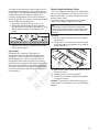
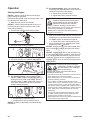
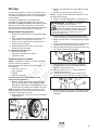
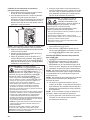
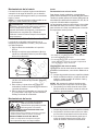
Install the wheel kit as follows:
1. Tip generator so that engine side is down. Tip
generator back slightly and slide narrow end of
one of the support legs under engine recoil.
NOTICE Be sure to slide support leg far enough under
engine recoil to prevent generator from tipping over.
2. Slide axle (A) through holes in generator frame.
3. Slide a black nylon washer (B) over axle.
4. Slide a wheel (C) over axle.
NOTICE Be sure to install wheel with raised hub
inboard.
5. Slide a flat washer (D) over axle.
6. Place an e-ring (E) in axle groove.
7. Install e-ring with pliers, squeezing from top of
e-ring to bottom of axle.
8. Repeat step 3 thru 7 to secure second wheel.
9. Tip generator back slightly and remove support
leg from under engine recoil.
10. Line up holes in support leg (F) with holes in
generator frame.
11. Attach support leg using two capscrews (G) and
two hex nuts (H). Tighten with 13 mm wrenches.
12. Repeat step 10 and 11 to secure second support
leg.
13. Attach cord wrap posts (J) to generator frame.
Tighten with an adjustable wrench.
14. Return generator to normal operating position
(resting on wheels and support legs).
J
A
C
D
B
E
H
G
F
CAUTION E-rings could cause eye injury.
E-rings could spring back and become
airborne when installing or removing,
resulting in moderate injury.
• Always wear eye protection when installing/removing e-rings.

Not for
Reproduction
10 troybilt.com
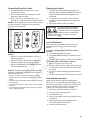
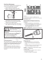
Moving Generator
1. Remove handle pin (A) from bracket on right side
of handle (viewing generator from engine end).
2. Pull folding handle to the upright position until
latch (B) locks into place.
3. Reinsert handle pin in bracket on right side of handle.
4. Place your foot onto the axle (C) located under
the recoil starter and pull back on the handle.
5. Always face generator and push or pull to desired
location. When moving generator on an incline,
always make sure you are uphill from generator.
6. Place foot on axle and gently let generator tip
forward to rest on support leg.
7. Remove handle pin from right side of handle.
8. Pull up on latch and push handle forward to fold
down handle.
Verify Engine Oil Level
The generator engine is shipped from the factory filled
with oil (API SJ or higher 10W-30). This allows for
generator operation in the widest range of temperature
and climate conditions. Before starting the engine,
check oil level and ensure that engine is serviced as
described in Maintenance.
NOTICE Any attempt to crank or start the engine
before it has been properly filled with the recommended
oil could result in equipment failure.
• Refer to Maintenance for oil fill information.
• Damage to equipment resulting from failure to follow this
instruction will void warranty.
NOTICE See Oil in the Maintenance section to review
oil recomendations. Verify provided oil in engine is the
correct viscosity for current ambient temperature.
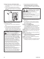
Add Fuel
Fuel must meet these requirements:
• Clean, fresh, unleaded gasoline.
• A minimum of 87 octane/87 AKI (91 RON). For
high altitude use, see High Altitude.
• Gasoline with up to 10% ethanol (gasohol) is
acceptable.
NOTICE Use of unapproved fuels could damage
generator and voids warranty.
• DO NOT use unapproved gasoline such as E15 and E85.
• DO NOT mix oil in gasoline or modify engine to run on
alternate fuels.
C
WARNING Body Crush/Tip Over Hazard.
Generator could tip over while moving
resulting in serious injury.
• Handle pin must be installed prior to moving generator.
A
B
WARNING Fuel and its vapors are extremely
flammable and explosive which
could cause burns, fire or explosion
resulting in death or serious injury.
WHEN ADDING FUEL
• Turn generator engine OFF and let it cool at least 2
minutes before removing fuel cap. Loosen cap slowly to
relieve pressure in tank.
• Fill fuel tank outdoors.
• DO NOT overfill tank. Allow space for fuel expansion.
• If fuel spills, wait until it evaporates before starting
engine.
• Keep fuel away from sparks, open flames, pilot lights,
heat, and other ignition sources.
• Check fuel lines, tank, cap and fittings frequently for
cracks or leaks. Replace if necessary.
• DO NOT light a cigarette or smoke.

Not for
Reproduction
11
To protect the fuel system from gum formation, mix in a
fuel stabilizer when adding fuel. See Storage. All fuel is
not the same. If you experience starting or performance
problems after using fuel, switch to a different fuel
provider or change brands. This engine is certified to
operate on gasoline. The emission control system for this
engine is EM (Engine Modifications).
1. Clean area around fuel fill cap, remove cap.
2. Slowly add unleaded gasoline (D) to fuel tank
(E). Be careful not to fill above the baffle (F). This
allows adequate space for fuel expansion as
shown.
3. Install fuel cap and let any spilled fuel evaporate
before starting engine.
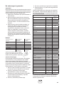
High Altitude
At altitudes over 5,000 feet (1524 meters), a
minimum 85 octane / 85 AKI (89 RON) gasoline is
acceptable. To remain emissions compliant, high
altitude adjustment is required. Operation without
this adjustment will cause decreased performance,
increased fuel consumption, and increased emissions.
See an authorized dealer for high altitude adjustment
information. Operation of the engine at altitudes below
2,500 feet (762 meters) with the high altitude kit is not
recommended.
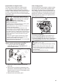
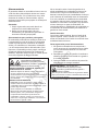
Attach Negative Battery Cable
Your unit is equipped with electric start capability but
can be started manually. If you choose not to use the
electric start feature, you do not need to connect the
negative battery cable.
The sealed battery on the generator pre–installed
except for the negative (black) battery cable.
To install:
1. Cut off tie wrap securing loose end of negative
(black) cable.
2. Using 8 mm or 5/16” wrenches, remove nut (A),
lock washer (B) and flat washer (C) on negative
battery terminal (—).
3. Slide negative battery cable (D) over screw (E) on
negative terminal.
4. Reattach washer and nut and tighten.
5. Verify that connections to battery and generator
are tight and secure.
NOTICE If your battery is discharged, charge prior
to use following the instructions in the section Battery
Charger.
FUEL
TANK
F
E
D
WARNING Battery posts, terminals and related
accessories contain lead and lead compounds -
chemicals known to the State of California to cause
cancer and reproductive harm. Wash hands after
handling.
E
D
A
B
C

Not for
Reproduction
12 troybilt.com
System Ground
The generator has a system ground that connects the
generator frame components to the ground terminals
on the AC output receptacles. The system ground is
connected to the AC neutral wire (the neutral is bonded
to the generator frame).
Special Requirements
There may be Federal or State Occupational Safety
and Health Administration (OSHA) regulations, local
codes, or ordinances that apply to the intended use of
the generator. Please consult a qualified electrician,
electrical inspector, or the local agency having
jurisdiction:
• In some areas, generators are required to be
registered with local utility companies.
• If the generator is used at a construction site,
there may be additional regulations which must
be observed.
Connecting to a Building’s Electrical
System
Connections for standby power to a building’s
electrical system must be made by a qualified
electrician. The connection must isolate the generator
power from utility power and must comply with all
applicable laws and electrical codes.
Portable Generator Location
Before starting the portable generator there are two equally
important safety concerns regarding carbon monoxide
(CO) poisoning and fire that must be addressed.
NOTICE Satisfying the RISK OF CARBON MONOXIDE
POISONING location requirements may not satisfy the
fire location requirements. Satisfying the RISK OF FIRE
location requirements may not satisfy the CARBON
MONOXIDE POISONING location requirements.
Operation Location of Portable Generator to REDUCE
THE RISK OF CARBON MONOXIDE POISONING
All fossil fuel burning equipment, such as a portable
generator, contains carbon monoxide (CO) gas in the
engine exhaust, a poisonous gas that could kill you in
minutes. You CANNOT smell it, see it, or taste it. Even
if you do not smell exhaust fumes, you could still be
exposed to carbon monoxide gas. The following must be
completed prior to starting the portable generator engine:
• By law it is required in many states to have a
Carbon Monoxide (CO) alarm (A) in operating
condition in your home. Install/maintain battery-
operated carbon monoxide alarms or plug-in carbon
monoxide alarms with battery back-up according to
the manufacturer’s instructions. A CO alarm is an
electronic device that detects hazardous levels of
CO. When there is a buildup of CO, the alarm will
alert the occupants by flashing visual indicator light
and alarm. Smoke alarms cannot detect CO gas.
WARNING
Generator voltage could cause
electrical shock or burn resulting in death or
serious injury.
• Use approved transfer equipment to prevent backfeed
by isolating generator from electric utility workers.
• When using generator for backup power, notify utility
company.
• Use a ground fault circuit interrupter (GFCI) in any damp
or highly conductive area, such as metal decking or steel
work.
• DO NOT touch bare wires or receptacles.
• DO NOT use generator with electrical cords which are
worn, frayed, bare or otherwise damaged.
• DO NOT operate generator in the rain or wet weather.
• DO NOT handle generator or electrical cords while
standing in water, while barefoot, or while hands or feet
are wet.
• DO NOT allow unqualified persons or children to operate
or service generator.
A

Not for
Reproduction
13
• Operate this product ONLY outside far away from
windows, doors and vents to reduce the risk of
carbon monoxide gas from accumulating and
potentially being drawn towards occupied spaces.
• DO NOT run this product inside homes, garages,
basements, crawlspaces, sheds, or other partially-
enclosed spaces even if using fans or opening doors
and windows for ventilation. Carbon monoxide can
quickly build up in these spaces and can linger for
hours, even after this product has shut off.
• Your neighbor(s) home may be exposed to the
engine exhaust from your portable generator and
must be considered when deciding on a location
for the safe operation of your portable generator.
• ALWAYS place this product downwind and point
the engine exhaust away from occupied spaces.
If you start to feel sick, dizzy, or weak while using this
product, shut it off and get to fresh air RIGHT AWAY. See
a doctor. You may have carbon monoxide poisoning.
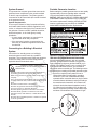
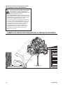
EXAMPLE OF LOCATION TO REDUCE
THE RISK OF CARBON MONOXIDE POISONING
Only use OUTSIDE
and FAR AWAY from
windows, doors and vents.
Direct exhaust AWAY
from windows, doors,
and vents.
KEEP
FAR AWAY
CO Alarm
in Living Areas
E
X
H
A
U
S
T
(
C
O
)
DO NOT OPERATE IN ANY OF THE FOLLOWING LOCATIONS
Generator too
close to home and
exhaust directed
towards windows,
doors and vents.
Garage
Attic
Living Area
Basement
Crawlspace
Entryway,
Porch
E
X
H
A
U
S
T
(
C
O
)

Not for
Reproduction
14 troybilt.com
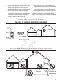
EXAMPLE OF LOCATION TO REDUCE THE RISK OF FIRE
Operation Location of Portable Generator to
REDUCE THE RISK OF FIRE
WARNING Exhaust heat/gases could ignite
combustibles, structures or damage fuel
tank causing a fire, resulting in death or
serious injury.
• Portable generator must be at least 5 feet (1.5 m) from
any structure, overhang, trees, windows, doors, any wall
opening, shrubs, or vegetation over 12 inches (30.5 cm)
in height.
• DO NOT place portable generator under a deck or other
type of structure that may confine airflow.
• Smoke alarm(s) MUST be installed and maintained
indoors according to the manufacturer’s instructions/
recommendations. Carbon monoxide alarms cannot
detect smoke.
• DO NOT place portable generator in manner other than
shown.
Direct exhaust AWAY from
windows, doors, and vents.
E
X
H
A
U
S
T
(
C
O
)
5 ft. (1.5 m) min.
5 ft. (1.5 m) min.

Not for
Reproduction
15
Features and Controls
Generator
Read this Operator’s Manual and safety rules before operating your generator.
Compare the illustrations with your generator, to familiarize yourself with the locations of various controls
and adjustments. Save this manual for future reference.
A - Main Control Panel — Permanently affixed to
generator. See Control Panel on next page.
B - Extend-a-panel™ — Connected to generator with
cord for remote operation. See Control Panel on
next page.
C - Spark Arrester Muffler — Exhaust muffler lowers
engine noise and is equipped with a spark arrester
screen.
D - Grounding Fastener — Consult your local agency
having jurisdiction for grounding requirements in
your area.
E - Cord — Extend-a-panel™ is connected to
generator with 20 Amp, 25 ft. (7.6 m) cord.
F - Identification Label — Provides model, revision
and serial number of generator. Please have these
readily available when calling for assistance.
G - Air Cleaner — Protects engine by filtering dust
and debris out of intake air.
H - Recoil Starter — Used to start the engine
manually.
J - Oil Fill Cap — Check and add engine oil here.
K - Fuel Valve — Used to turn fuel supply on and off
to engine.
L - Fuel Tank — Capacity of 8.5 U.S. gallons (32.2 l).
Items Not Shown:
Engine Identification — Provides model, type and
code of engine. Please have these readily available if
calling for assistance.
Oil Drain Plug — Drain engine oil here.
E
A
L
B
H
C
K
G
J
D
F

Not for
Reproduction
16 troybilt.com
Control Panel
A - 120 Volt AC, 20 Amp, GFCI Duplex Receptacles
— May be used to supply electrical power for the
operation of 120 Volt AC, 20 Amp, single phase,
60 Hz electrical, lighting, appliance, tool and motor
loads.
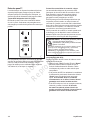
B - On/Off Switch — Set this switch to ON (I) before
starting engine. Set switch to OFF (0) to shut off
engine.
C - Battery Float Charger Jack — Use battery float
charger jack to keep the starting battery charged
and ready for use.
D - Display Button — Push to scroll through LCD
screens on Extend-a-panel™. Also push and hold
for a minimum of 3 seconds to reset maintenance
reminders and security features.
E - Choke Control — Used when starting a cold
engine.
F - Start Switch — Push and hold in “Start” position
for a maximum of 5 seconds during each start
attempt, until engine starts.
G - Circuit Breakers (AC) — The 120 Volt AC, 20A
GFCI duplex receptacles are provided with “push
to reset” circuit breakers to protect the generator
against electrical overload.
H - Rocker Switch Main Circuit Breaker — The
120/240 Volt AC, 30A locking receptacle is
provided with a rocker switch circuit breaker to
protect generator against electrical overload.
J - 120/240 Volt AC, 30 Amp Locking Receptacle
— May be used to supply electrical power for the
operation of 120 and/or 240 Volt AC, 30 Amp,
single phase, 60 Hz electrical, lighting, appliance,
tool and motor loads.
K - Rocker Switch Cordset Circuit Breaker — The
cordset on main panel is provided with a double
pole rocker switch circuit breaker to protect
generator against electrical overload.
G
A
B
C
D
K
H
J
E
F

Not for
Reproduction
17
Battery Charger
Use battery float charger jack to keep the starting
battery charged and ready for use. Battery charging
should be done in a dry location, such as inside a
garage.
1. Plug charger into unit’s “Battery Float Charger”
jack, which is located above on/off switch. Plug
battery charger into a 120 Volt AC wall receptacle.
2. Unplug charger from unit and wall outlet when
generator is being started and while it is in operation.
3. Keep this charger plugged in when generator is
not in use to prolong battery life. The charger has
a built in float equalizer and will not overcharge
the battery, even when plugged in for an extended
period of time.
NOTICE See Battery Maintenance for additional
information.
Cord Sets and Receptacles
Use only high quality, well-insulated, grounded
extension cords with the generator’s receptacles.
Inspect extension cords before each use.
Check the ratings of all extension cords before you use
them. Check the operator’s manuals of devices for the
manufacturer’s recommendations.
A double pole rocker switch circuit breaker is provided
to protect the locking receptacle. If this circuit breaker is
tripped, all receptacles are disconnected.
120/240 Volt AC, 30 Amp, Locking Receptacle
Use a NEMA L14-30 plug with this receptacle.
Connect a 4-wire cord set rated for 250 Volt AC loads
at 30 Amps (or greater). You can use the same 4-wire
cord if you plan to run a 120 Volt load.
This receptacle powers 120/240 Volt AC, 60 Hz, single
phase loads requiring up to 7,000 watts of power
(7.0 kW) at 29.1 Amps for 240 Volts or two independent
120 Volt loads at 29.1 Amps each. The outlet is
protected by a two pole rocker switch circuit breaker.
NOTICE
Receptacles may be marked with rating
value greater than generator output capacity.
• NEVER attempt to power a device requiring more
amperage than generator or receptacle can supply.
• DO NOT overload the generator. See Don’t Overload
Generator.
WARNING Damaged or overloaded electrical
cords could overheat, arc, and burn
resulting in death or serious injury.
• ONLY use cords rated for your loads.
• Follow all safeties on electrical cords.
• Inspect cord sets before each use.
240V
120V
120V
W (Neutral)
X (Hot)
Y (Hot)
NEMA L14-30
Ground (Green)
4-Wire Cord Set

Not for
Reproduction
18 troybilt.com
Extend-a-panel™
A double pole rocker switch circuit breaker on the main
panel is provided to protect the cordset off main panel.
If this circuit breaker is tripped, all power from cordset
is disconnected.
120 Volt AC, 20 Amp, GFCI Duplex Receptacles
The Extend-a-panel™ has two 120 Volt, 20 Amp GFCI
duplex receptacles. Each receptacle is protected
against overload by push-to-reset circuit breakers.
Use each receptacle to operate 120 Volt AC,
single-phase, 60 Hz electrical loads requiring up to
2,400 watts (2.4 kW) at 20 Amps of current. Use cord
sets that are rated for 125 Volt AC loads at 20 Amps
(or greater).
Ground Fault Protection
The duplex receptacles are equipped with Ground
Fault Circuit Interrupter (GFCI) protection. This device
meets applicable federal, state and local codes. The
generator’s locking receptacle is not protected by a
Ground Fault Circuit Interrupter (GFCI).
The GFCI protects against electrical shock that may be
caused if your body becomes a path which electricity
travels to reach ground. This could happen if you touch
a “Live” appliance or wire, or are touching plumbing or
other materials that connect to the ground.
When protected by a GFCI, one may still feel a shock,
but the GFCI should cut current off quickly enough so
that a person in normal health should not suffer any
serious electrical injury.
Testing the GFCI
Test your GFCI outlet prior to each use, as follows:
• Push the “Test” button. The “Reset” button should
pop out, which should allow no power to reach the
outlet. Use a test lamp in each outlet to test this.
• If the GFCI tests good, restore power by pressing
the “Reset” button firmly until it is fully in place
and locks in that position. If the GFCI outlet
does not reset properly, do not use the outlet.
Call or take your generator to a local service
center.
• If the GFCI trips by itself at any time, reset and
test the outlet. If the reset button does not pop
out when the test button is pressed, do not
use the outlet. Call or take your generator to
a local service center.
WARNING
Generator voltage could cause
electrical shock or burn resulting in death or
serious injury.
• Contact with the hot and neutral conductor at the same
time can cause electrical shock or burn, even if the
circuit is GFCI protected.
• Before using the GFCI receptacle, ALWAYS push the
test button to insure it works.

Not for
Reproduction
19
Extend-a-panel™ LCD
The Extend-a-panel™ also has a built in LCD display
with alarm system to monitor the following features:
• Dual Load Monitor (Panel and Total)
• Maintenance Reminder
• Security Warning
• Generator Shutdown
Dual Load Monitor
The dual load monitor measures the wattage output
of the Extend-a-panel™ 120V, 20A receptacles and
will display “PANEL” along with bars and percentage
of load. Each duplex receptacle will operate 120 Volt
AC, single-phase, 60 Hz electrical loads requiring up to
2,400 watts (2.4 kW) at 20 Amps of current for a total
of 4,800 watts (4.8 kW).
The “TOTAL” displays the wattage output of all
receptacles on the main panel and Extend-a-panel™.
The LCD will display “TOTAL” along with bars
and percentage of load. If only the 120/240V, 30A
receptacle is used, the LCD on the Extend-a-panel™
will display “TOTAL” only.
If the wattage output of either the “PANEL” or “TOTAL”
is between 90% and 100%, the text will flash. If
either reaches 101%, the LCD display will change to
“OVERLOAD REMOVE LOAD”. An audible beep will
sound until enough load is removed and the wattage
output is below 101%.
Maintenance Reminder
The Extend-a-panel™ also has a built in maintenance
reminder to alert you to check oil, change air filter,
change oil, and change spark plug. The LED will
display the following screens for the different
maintenance intervals:
• “CHECK OIL 8HRS HOLD TO RESET” after
every 8 hours of operation.
• “AIR FILTER 25HRS HOLD TO RESET” after
every 25 hours of operation.
• “CHANGE OIL 50HRS HOLD TO RESET” after
every 50 hours of operation.
• “SPARK PLG 100HRS HOLD TO RESET” after
every 100 hours of operation.
You must push and hold the display button on the
Extend-a-panel™ for a minimum of 3 seconds to reset
the timer after each maintenance interval.
Security Warning
The Extend-a-panel™ has a built in security warning
that sounds an audible beep when the generator shuts
down or if the Extend-a-panel™ is disconnected from
the generator. The LCD will display “GENERATOR
SHUTDOWN” and sound an audible beep for 5
seconds. The LCD backlight will turn off when the
audible beep stops.
The security warning can be turned off if desired.
To turn the audible beep from the security warning
off, push the display button to scroll through the
maintenance screens until the LCD displays
“SECURITY WRNG ON HOLD TO SET”. Push
and hold the display button until the LCD displays
“SECURITY WRNG OFF HOLD TO SET”.
NOTICE By turning the security warning off, the
audible beep will also be turned off if the panel or
generator is overloaded.
Generator Shutdown
In order for the generator shutdown feature to work as
described in Security Warning, you must install 4 AAA
batteries (not supplied) into the back of the Extend-a-
panel™.

Not for
Reproduction
20 troybilt.com
Operation
Starting the Engine
NOTICE Always unplug the battery float charger
before starting the generator.
Disconnect all electrical loads from the generator. Use
the following start instructions:
1. Make sure unit is on a level surface.
NOTICE Failure to start and operate the unit on a
level surface will cause the unit not to start or shut
down during operation.
2. Turn the fuel valve (A) to the ON (I) position.
3. Set on/off switch to ON (I) position.
4. Pull choke handle out to CHOKE ( ) position.
5A. For electric starting, push and hold the start
switch in “Start” position until generator starts. To
prolong the life of starter components, DO NOT
hold start switch in “Start” position for more than
5 seconds, and pause for at least 30 seconds
between starting attempts.
• If engine starts, proceed to step 7.
• If engine fails to start, proceed to step 6.
NOTICE If battery is discharged, use manual starting
instructions.
5B. For manual starting, grasp recoil handle and
pull slowly until slight resistance is felt. Then pull
rapidly one time only to start engine.
• If engine starts, proceed to step 7.
• If engine fails to start, proceed to step 6.
6. Push in the choke handle half way, and pull recoil
handle twice or push and hold the start switch in
the “Start” position as described in step 5A.
• If engine fails to start, repeat steps 4 thru 5.
7. As the engine warms up, gradually push choke
handle in to RUN (
) position.
NOTICE If engine floods, push choke handle all the
way in to RUN ( ) position, and crank until engine
starts.
NOTICE If engine starts after 3 pulls but fails to run,
or if unit shuts down during operation, make sure unit
is on a level surface and check for proper oil level in
crankcase. This unit may be equipped with a low oil
protection device. If so, oil must be at proper level for
engine to start.
A
WARNING Exhaust heat/gases could ignite
combustibles, structures or damage
fuel tank causing a fire, resulting in
death or serious injury.
Contact with muffler area could cause burns
resulting in serious injury.
• DO NOT touch hot parts and AVOID hot exhaust gases.
• Allow equipment to cool before touching.
• Keep at least 5 feet (1.5 m) of clearance on all sides of
generator including overhead.
• It is a violation of California Public Resource Code,
Section 4442, to use or operate the engine on any forest-
covered, brush-covered, or grass-covered land unless
the exhaust system is equipped with a spark arrester, as
defined in Section 4442, maintained in effective working
order. Other states or federal jurisdictions may have
similar laws.
Contact the original equipment manufacturer, retailer,
or dealer to obtain a spark arrester designed for the
exhaust system installed on this engine.
• Replacement parts must be the same and installed in the
same position as the original parts.
WARNING Starter cord kickback (rapid
retraction) will pull hand and arm toward
engine faster than you can let go which
could cause broken bones, fractures,
bruises, or sprains resulting in serious injury.
• When starting engine, pull cord slowly until resistance is
felt and then pull rapidly to avoid kickback.
• NEVER start or stop engine with electrical devices
plugged in and turned on.
Page is loading ...
Page is loading ...
Page is loading ...
Page is loading ...
Page is loading ...
Page is loading ...
Page is loading ...
Page is loading ...
Page is loading ...
Page is loading ...
Page is loading ...
Page is loading ...
Page is loading ...
Page is loading ...
Page is loading ...
Page is loading ...
Page is loading ...
Page is loading ...
Page is loading ...
Page is loading ...
Page is loading ...
Page is loading ...
Page is loading ...
Page is loading ...
Page is loading ...
Page is loading ...
Page is loading ...
Page is loading ...
Page is loading ...
Page is loading ...
Page is loading ...
Page is loading ...
Page is loading ...
Page is loading ...
Page is loading ...
Page is loading ...
Page is loading ...
Page is loading ...
Page is loading ...
Page is loading ...
Page is loading ...
Page is loading ...
Page is loading ...
Page is loading ...
-
 1
1
-
 2
2
-
 3
3
-
 4
4
-
 5
5
-
 6
6
-
 7
7
-
 8
8
-
 9
9
-
 10
10
-
 11
11
-
 12
12
-
 13
13
-
 14
14
-
 15
15
-
 16
16
-
 17
17
-
 18
18
-
 19
19
-
 20
20
-
 21
21
-
 22
22
-
 23
23
-
 24
24
-
 25
25
-
 26
26
-
 27
27
-
 28
28
-
 29
29
-
 30
30
-
 31
31
-
 32
32
-
 33
33
-
 34
34
-
 35
35
-
 36
36
-
 37
37
-
 38
38
-
 39
39
-
 40
40
-
 41
41
-
 42
42
-
 43
43
-
 44
44
-
 45
45
-
 46
46
-
 47
47
-
 48
48
-
 49
49
-
 50
50
-
 51
51
-
 52
52
-
 53
53
-
 54
54
-
 55
55
-
 56
56
-
 57
57
-
 58
58
-
 59
59
-
 60
60
-
 61
61
-
 62
62
-
 63
63
-
 64
64


Simplicity 030477A-00 User guide
- Category
- Power generators
- Type
- User guide
Ask a question and I''ll find the answer in the document
Finding information in a document is now easier with AI
in other languages
Other documents
-
Troy-Bilt 6250 Watt Portable Generator User manual
-
Troy-Bilt 30248 User manual
-
-
Troy-Bilt 01919-1 User manual
-
-
Briggs & Stratton 6250A User manual
-
-
Troy-Bilt PORTAbLE GENERATOR User manual
-
Echo EG-10000 User manual
-
Husqvarna 1365GN Owner's manual