Page is loading ...

© 2013 Pentair, Ltd. All Rights Reserved. HYD739 (Rev. 03/04/13)
293 WRIGHT STREET, DELAVAN, WI 53115 WWW.HYDROMATIC.COM
PH: 8889578677
Installation/Operation/Parts
For further operating, installation,
or maintenance assistance:
Call 1-888-957-8677
English ........................ Pages 2-15
Installation/Fonctionnement/Pièces
Pour plus de renseignements
concernant l’utilisation,
l’installation ou l’entretien,
Composer le
1 (888) 957-8677
Français .................. Pages 16-29
Instalación/Operación/Piezas
Para mayor información sobre el
funcionamiento, instalación o
mantenimiento de la bomba:
Llame al 1-888-957-8677
Español .................. Paginas 30-44
OWNER’S MANUAL
Battery Backup System
NOTICE D’UTILISATION
Système de secours à batterie
MANUAL DEL USUARIO
Systema de respaldo de la batería
3467 0799 P4500L
ALARM RESET
SOFT RESET
AUDIBLE ALARM
DISABLE
CHARGING - YELLOW
CHARGED - GREEN
LOW BATTERY ALARM
AUDIBLE ALARM
SILENCE
PUMP RUN ALARM
A.C.POWER ON
MICRO PROCESSOR CONTROLLED
5 STAGE BATTERY CHARGE/MAINTAINER
12 VOLT 8 AMP
ALWAYS READ WARNINGS IN INSTRUCTION
MANUAL BEFORE USING.
3466 0799 MY
FG100-A1
FG200-A1

Safety 2
READ AND FOLLOW
SAFETY INSTRUCTIONS!
This is the safety alert symbol. When you see this
symbol on your pump or in this manual, look for
one of the following signal words and be alert to the
potential for personal injury!
DANGER warns about hazards that will
cause serious personal injury, death or major property
damage if ignored.
WARNING warns about hazards that can
cause serious personal injury, death or major property
damage if ignored.
CAUTION warns about hazards that will or
can cause minor personal injury or property damage if
ignored.
The word NOTICE indicates special instructions which
are important but not related to hazards.
1. To avoid risk of serious bodily injury due to electrical
shock or burns and property damage due to flooding,
read the safety instructions carefully before installing
pump.
Battery acid is corrosive. Do not spill on
skin, clothing, or battery charger. Wear eye and head
protection when working with battery. Connect and
disconnect DC output terminals only after removing
the charger from the AC outlet. Never allow the DC
terminals to touch each other.
Hazardous Voltage. Can cause severe or
fatal electrical shock. Do not plug in or unplug battery
charger while standing on a wet floor or in water. Be
sure one hand is free when plugging in or unplugging
charger. If basement floor is wet, disconnect power to
basement before walking on floor.
Risk of flooding. Do not run pump dry.
To do so will damage seals and can cause leaking and
property damage.
2. Follow local and/or national plumbing and electrical
codes when installing the system. A ground fault
circuit interrupter (GFCI) is recommended for use on
any electrical appliance submerged in water.
3. Use this system only for backup sump pump duty
in a residential application. It is not designed as a
primary sump pump.
4. Do not lift pump by electrical cord.
Risk of electrical shock. Do not lift the
pump by the electrical cord; lift pump only by the
discharge pipe, lifting ring or handle on the pump. Lifting
by the cord can damage the cord.
5. Pump clear water only with this pump.
6. Pump is permanently lubricated at the factory. Do
not try to lubricate it!
7. Keep battery charger and battery box off of the floor
and in a dry, cool, well ventilated area.
NOTICE: If a Carbon Monoxide (CO) sensor is
installed, it must be at least 15 feet away from
battery charger in order to avoid nuisance CO
alarms. Please refer to your CO detector’s installation
guidelines for more information.
8. To avoid danger of fire or explosion, keep sparks and
flame (pilot light) away from battery.
9. Maximum vertical pumping distance is 16 feet
(4.9M) for Model FG100-A1 and 18 feet (5.5M) for
Model FG200-A1.
10. Make sure sump is clear of debris. Debris can
damage the pump which can result in flooding.
California Proposition 65 Warning
This product and related accessories contain
chemicals known to the State of California to cause
cancer, birth defects or other reproductive harm.
GENERAL INFORMATION
The battery back-up sump system is not a sub stitute for
your primary sump pump. It is designed to temporarily
back up your primary sump pump during a power outage
or other problem which prevents normal operation of
the primary pump. Do not use this system to pump
flammable liquids or chemicals. Pump clear water only
with this pump.
Keep battery charger dry and protected from damage.
In an emergency (such as an extended power outage)
which depletes the system deep cycle battery, your
automobile battery may be temporarily substituted. Be
sure to replace the system deep cycle battery as soon
as possible. Use of an automobile battery instead of a
deep cycle battery in this system will significantly reduce
system total performance. Automobile batteries are not
designed for this type of application and will be quickly
ruined by the repeated charge/discharge cycling. Do
not use GEL-type batteries or maintenance-free (sealed)
batteries with this charger. GEL-type batteries require a
lower voltage than the charger is designed for; they may
overcharge. Maintenance-free (sealed) batteries require a
higher voltage and may never reach full charge.
NOTICE: This unit is not designed for applications
involving salt water or brine! Use with salt water or brine
will void warranty.

Table of Contents 3
Page
General Safety .....................................................................................................2
Warranty..............................................................................................................3
Installation ......................................................................................................4-12
Operation .....................................................................................................13-14
Troubleshooting ................................................................................................. 14
Repair Parts .......................................................................................................15
Limited Warranty
HYDROMATIC warrants to the original consumer purchaser (“Purchaser” or “You”) of HYDROMATIC Sump Pumps,
Effluent Pumps, Sewage Pumps (other than 2-1/2”), and Package Systems, that they will be free from defects in material and
workmanship for the Warranty Period of 36 months from date of manufacture.
Our warranty will not apply to any product that, in our sole judgement, has been subject to negligence, misapplication,
improper installation, or improper maintenance. Without limiting the foregoing, operating a three phase motor with single phase
power through a phase converter will void the warranty. Note also that three phase motors must be protected by three-leg,
ambient compensated, extra-quick trip overload relays of the recommended size or the warranty is void.
Your only remedy, and HYDROMATIC’s only duty, is that HYDROMATIC repair or replace defective products (at
HYDROMATIC’s choice). You must pay all labor and shipping charges associated with this warranty and must request warranty
service through the installing dealer as soon as a problem is discovered. No request for service will be accepted if received after
the Warranty Period has expired. This warranty is not transferable.
EXCEPTIONS: Hydromatic Special Application Pumps, Battery Back-Up Sump Pumps, Filtered Effluent Pumps, Grinder
Pumps, and 2-1/2” Sewage Pumps are warranted for a period of 12 months from date of purchase or 18 months from date of
manufacture, whichever comes first.
HYDROMATIC SHALL NOT BE LIABLE FOR ANY CONSEQUENTIAL, INCIDENTAL, OR CONTINGENT
DAMAGESWHATSOEVER.
THE FOREGOING LIMITED WARRANTIES ARE EXCLUSIVE AND IN LIEU OF ALL OTHER EXPRESS AND IMPLIED
WARRANTIES, INCLUDING BUT NOT LIMITED TO IMPLIED WARRANTIES OF MERCHANTABILITY AND FITNESS FOR
A PARTICULAR PURPOSE. THE FOREGOING LIMITED WARRANTIES SHALL NOT EXTEND BEYOND THE DURATION
PROVIDED HEREIN.
Some states do not allow the exclusion or limitation of incidental or consequential damages or limitations on the duration of an
implied warranty, so the above limitations or exclusions may not apply to You. This warranty gives You specific legal rights and
You may also have other rights which vary from state to state.
This Limited Warranty is effective June 1, 2011 and replaces all undated warranties and warranties dated before June 1, 2011.
HYDROMATIC
293 Wright Street, Delavan, WI 53115
Phone: 888-957-8677 • Fax: 800-426-9446 • Web Site: hydromatic.com

Installation 4
BATTERY BACKUP SYSTEM
INSTALLATION AND OPERATION
NOTICE:
• Install this system during a time when the primary
pump will not be needed. Gather all supplies before
starting. Read all warnings and installation steps
before you start.
• Bepreparedforwatertoleakfromthecouplingor
piping when disassembling or cutting the discharge
pipe. Protect system components, tools and supplies
from getting wet. Dry any work areas that get wet.
BASIC TOOLS AND
MATERIALS NEEDED
Channel locks or large pliers
Tape measure
Socket wrench or 5/16" Nut driver
Side cutters
Hacksaw (to cut PVC pipe)
Medium size pliers
Pencil
PTFE pipe thread sealant tape
PVC glue (solvent weld)
PVC pipe cleaner
Cloth towel
Size 24M Marine Deep Cycle Battery (sold separately)
or a
Size 27M Marine Deep Cycle Battery (sold separately)
Required Battery Capacity:
FG100-A1 – 100 ampere-hour maximum.
FG200-A1 – 130 ampere-hour maximum.
Personal injury and flood hazard. Do not
turn the pump on until all the fittings are glued and the
glue has dried. Loose fittings can explode off of pipes
and cause personal injury and flooding.
Remove Primary Pump From Sump Pit:
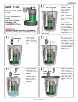
1. Locate the “on” water level of the primary sump
pump. Mark this location on the discharge pipe with
a pencil. See Figure 1.
2. Drain the sump pit. The water level must be pumped
down as low as possible before going on to the next
step. To drain the sump pit follow either step “2A” or
“2B” (below).
2A. Raise the float on the float switch until the
pump turns on. Use a wooden broom handle or
a stick to do this.
2B. If the sump pump has a piggy-back type power
cord, remove the float switch power cord plug
from the outlet and plug the pump power cord
plug directly into the outlet. See Figure 2.
Electrical shock hazard. Shock can
burn or kill. Do not use metal or any other electrical
conducting material to raise the float. Do not make
contact with the water in the sump pit. Failure to
follow this warning can result in personal injury or
death.
3. Drain the sump.
NOTICE: Do not let the pump run dry. This will
damage the pump.
4. Unplug the pump.
'Turn on'
water level of
Primary Pump
Sump Pit
Check
Valve
Remove the
hose coupling
or mark the
1st cut here.
Support the
Pipe before
cutting.
3547 1099
Mark pipe with
pencil here
(2nd cut).
Figure 1 – Mark and cut pipe as shown
Separate the float switch cord plug
from the sump pump cord plug.
Unplug the "Piggy-back"
float switch cord plug and
the pump power cord plug
from the grounded
electrical outlet.
Plug the pump power cord plug
directly into the outlet.
Grounded
Electrical
Outlet
4166 0402
1.
2.
3.
Figure 2 - To bypass the float switch

Installation 5
5. To separate the primary pump from the discharge pipe:
5A. For applications with hose couplings: remove
the coupling clamps with a nut driver.
5B. For applications without rubber couplings: cut
the PVC discharge pipe with a hacksaw above
the basement floor, at a comfortable level. New
rubber couplings are included for reassembly.
See Figure 1 on Page 4.
NOTICE: The discharge pipe is filled with water.
Drain the water from the discharge pipe assembly.
Keep the work area dry.
Risk of pinching hands or fingers. To
avoid a hand injury from a collapse of plumbing,
support the pipe above the separation before cutting
or disassembly. See Figure 1.
6. Lift the primary pump and discharge pipe assembly
out of the sump.
Risk of electrical shock. Do not lift the
pump by the electrical cord; lift pump only by the
lifting ring, discharge pipe, or handle on the pump.
Lifting by the cord can damage the cord.
INSTALL BACKUP PUMP
There are two ways to install the Battery Back-up Pump.
Method A and Method B. See Figure 3 to determine
which method to use. Both methods are acceptable.
Method A
Method A suggests installing both of the pumps on the
floor of the sump pit. See Figure 4. The minimum required
sump basin diameter, at the bottom of the pit and the
recommended depth of the sump basin is 18".
Some additional materials you will need are 2 1-1/4" 90°
elbows and 2 1-1/4" close pipe nipples.
Figure 5 - Remove the pre-assembled check valve
Battery Back-up Pump comes
preassembled with the check
valve assembly installed on the
discharge.
Remove this check
valve assembly.
Elbow
Back-up Pump
Discharge
Tee
3548 1099 CVR
Check
Valve
Assembly
Close
Pipe
Nipple
(The valve
flap opens
away from the
pump outlet)
Water
Flow
through
valve
Figure 3 - Choose an installation method
Sump Pit
Diameter at
base at least
18"?
No No
No
No
Yes
Yes
Yes
Yes
BBU System may still
be installed but the
installation may need
to be changed.
4079 0502
Method B
Sump Pit Depth
18-22"?
Sump Pit Depth
at least 22"?
Method A
Sump Pit
Diameter at
base at least
13.5"?
Figure 4 - Method A installation diagram
Second Cut:
at Marked
Water Line
First Cut:
Backup Pump Installation
(Method A)
Not to Scale
Switches and
Wiring omitted
for clarity
1-1/2"x1-1/4"
Reducer
bushing
1-1/2"x1-1/4"
Reducer bushing
Tee
1-1/2"x 1-1/2"
slip x 1-1/4" FNPT
Short Length
of Discharge Pipe
(may vary)
Primary Sump
Pump Check Valve
to prevent
recirculation
into the sump.
Cut-Off piece of
discharge pipe.
Hose Coupling
with Clamps
1-1/4" Elbow
1-1/4"
Elbow
Close
Pipe
Nipple
(1-1/4"
x 1-1/4")
Back-up Pump
Discharge Port
Primary Pump
Discharge Port
(1 Nipple
is included
with the
back-up
pump
package)
3548 1099 A
Check Valve
Assembly

1. Make the second cut in the discharge pipe at the
pencil mark as shown in Figure 1 on page 4, and
in Figure 4, on Page 5. Clean the pipe ends with a
cloth towel and set the cut-off piece of discharge
pipe aside.
2. Remove the check valve assembly (Key No. 4 on
Page 15) from the battery back-up pump (Key No. 5)
discharge and set it aside. See Figure 5. The check
valve assembly will be used later, during assembly.
3. Thread a 90° elbow (purchased locally) onto the
discharge of the back-up pump.
4. Wrap the threads of all 3 of the close pipe nipples
(Key No. 3) with 2 turns of PTFE pipe thread sealant
tape and thread one of them into the elbow. Set the
other 2 aside.
5. Thread the check valve assembly, removed back in
step 2, onto the close pipe nipple.
NOTICE: Make sure the check valve is installed in the
correct direction. See the inset drawing in Figure 5.
6. Thread a close pipe nipple into the other end of the
check valve.
7 Thread the second 90° elbow onto the pipe nipple.
8. Thread the last pipe nipple into the elbow.
9. Thread the tee onto the pipe nipple and set this
assembly aside.
10. Install a short length of pipe into the top of the check
valve in the primary pump discharge. See Figure 6.
NOTICE: There must be a check valve installed in
the Primary Sump Pump discharge pipe between the
tee and the Primary Sump Pump. This will prevent
recirculation into the Primary Pump when the
Backup Sump Pump comes on.
11. Slip a reducer bushing (Key No. 2A) onto the end of
the pipe coming from the primary pump discharge.
Do not glue this connection yet.
NOTICE: If your discharge pipe diameter is 1-1/4",
you will need to glue the reducer bushings into the
tee first and then slip the cut off piece of discharge
pipe into the bushing.
12. Slip the tee and the back-up pump subassembly onto
the reducer bushing.
13. Glue the cut off piece of pipe into the top of the
reducer bushing in the top of the tee.
14. Mount the float switch assembly (Key No. 7) loosely
to the discharge pipe with the cable ties (Key Nos.
7A & 7B). See Figure 6. Approximately 2.5” (63.5
mm) of cord length should be left between the
float and the clamp. Do not tighten the cable ties.
Adjustments may be needed later.
15. Skip to the section “Cut the Discharge Pipe”, Page 7.
Method B
Method B suggests installing the back-up pump above
the primary sump pump. See Figure 7. The minimum
required sump basin diameter for this type of installation
is 13.5" at the bottom of the pit, and the minimum
recommended depth of the basin is 22".
1. Make a second cut in the discharge pipe at the pencil
mark made in step 1, on Page 4, and set the cut-off
piece of discharge pipe aside. See Figures 1 and 7.
Float Switch
Tether Length
2.5" (63.5 mm)
Te e
Hose
Coupling
and Clamps
Discharge
Pipe
Cable Ties
2" Minimum
To the
back-up
pump
discharge
pipe.
Short length
of discharge
Pipe (length
may vary).
Check valve
3546 1099 S521
Primary Sump
Pump Discharge
Pipe
Figure 6 - Back-up pump float switch tether length and
discharge pipe
Backup Pump Installation
(Method B)
Not to Scale
Switches and
Wiring omitted
for clarity
3548 1099 S521 ALT
1-1/2"x1-1/4"
Reducer
Bushing
1-1/2"x1-1/4"
Reducer
Bushing
Tee
Close
Pipe
Nipple
Primary Pump
Discharge Pipe
Primary Sump Pump
Check Valve to Prevent
Recirculation into Sump
Check Valve
Assembly
(Included)
Backup
Sump
Pump
Cut-Off piece of
discharge pipe.
Hose Coupling
with Clamps
Second Cut:
at Marked
Water Line
First Cut:
Basement
Floor
Sump
Pit
Figure 7 – Method B installation diagram
Installation 6

Installation 7
2. Wrap the threads of the close nipple (Key No. 3 on
Page 12) counterclockwise with 2 turns of PTFE pipe
thread sealant tape and set aside.
NOTICE: There must be a check valve installed in
the Primary Sump Pump discharge pipe between the
tee and the Primary Sump Pump. This will prevent
recirculation into the Primary Pump when the
Backup Sump Pump comes on.
3. The backup pump (Key No. 6) and check valve
assembly (Key Nos. 4 and 5) come preassembled.
Thread the close pipe nipple into the check valve.
4. To thread the tee (Key No. 2B - also included
reducer bushings) into the close nipple:
Hold the check valve assembly with the channel
locks, insert the screwdriver into the tee for leverage,
and tighten the tee with the screwdriver. Finish with
the tee in a straight up and down (vertical) position.
5. Clean the pipe ends with the cloth towel.
6. Glue the cut-off piece of discharge pipe into the top
of the tee.
NOTICE: If your pipe is 1-1/4", you will need to
glue the reducer bushings into the tee and glue the
pipe into the bushing. Place the assembly onto the
primary discharge pipe. Do not glue the tee onto the
primary pump discharge pipe.
7. Mount the back-up pump float switch assembly (Key
No. 7) loosely to the discharge pipe with the cable
ties (Key Nos. 7A & 7B). See Figure 6, on Page 6.
Approximately 2.5" (63.5 mm) of cord length should
be left between the float and the clamp. Do not
tighten the cable ties. Adjustments may be needed
later.
Cut the Discharge Pipe:
1. Put the double pump assembly into the sump pit.
NOTICE: The discharge pipe now overlaps the
discharge pipe that leads outside.
2. Mark the discharge pipe where it should be cut. Be
sure to leave a 1/4" air gap between the ends of the
pipes. This gap will absorb the noise from vibration
and allow for flexibility.
3. Make the third cut. See Figure 8.
TRIAL ASSEMBLY OF DOUBLE PUMP
ASSEMBLY IN THE SUMP PIT:
1. Connect the discharge pipe to the exterior discharge
pipe with the rubber coupling and clamp kit (Key
No. 1). Do not tighten the clamps until all the final
adjustments are complete.
2. Make the final adjustments. Make sure the pumps
and the switches do not interfere with each other.
Make sure there is plenty of room for the float
switches to either swing or to move up and down
from their “off” to their “on” positions.
Mark and Glue Assembly:
1. Mark the pipe and the fittings at all the connections
with a pencil. These marks will be used as a
reassembly guide while gluing to be sure everything is
still in the right place and nothing has moved.
2. Loosen the rubber coupling and clamp connection.
3. Carefully pull the double pump assembly back out of
the pit.
4. Take the tee assembly off of the primary discharge
pipe. Do Not unscrew any of the PTFE pipe thread
sealant taped pipe nipple connections.
5. Clean all the PVC pipe ends with the PVC cleaner.
Hazardous fumes. Follow the cement
and cleaner manufacturers instructions. Use the PVC
cement in a well ventilated area away from fire or
flames.
6. Glue the PVC fittings where indicated by the pencil
marks. Wait 10 minutes for the glue to cure.
Final Assembly:
1. Put the double pump assembly back into the pit.
2. Install and tighten the rubber coupling and clamp kit.
3. Make the final float switch adjustments and tighten
the cable ties.
1/4" air gap
Make the Third Cut
(the overlap plus
the 1/4" air gap).
Exterior
discharge
pipe
Exterior
discharge
pipe
Method A Method B
overlap
overlap
3549 1099 S521
Sump basin
inlet pipe (from
drain tiles to
sump basin).
Note: Always install the back-up sump pump as close
to the bottom of the sump pit as possible.
2"
2"
Previously marked
"on" water level
of Primary Sump Pump.
(See Figure 1, Page 4)
Recommended Minimum
Figure 8 – Make the third cut to remove the excess
discharge pipe

Installation 8
ELECTRICAL CONNECTIONS
Hazardous voltage. Can cause serious or
fatal electrical shock. Review safety instructions before
operating charger. Do not modify cord or plug.
CHARGER/BATTERY INSTALLATION
NOTICE: An alarm, located in the junction box,
automatically sounds when the system runs if the alarm
is in the “Enable” position. The alarm is silenced when
the alarm switch is in the “Disable” position.
Model Number FG100-A1:
1. Apply two pieces of two-sided tape (provided, Key
No. 9) to the back of the junction box. Press the
junction box onto the battery box as illustrated in
Figure 9 and on Page 15 (Exploded View).
2. Connect the charger as shown in Table I and
Figure 9.
3. Plug the charger into a 115-120 Volt AC outlet
deliv er ing at least 15 amps. Do not use a switch
controlled outlet. Mark circuit in main power panel
“Backup sump pump power supply; do not turn off”.
4. With the charger properly connected and plugged in,
the panel on the front of the charger will show one
of the conditions illustrated in Figure 10.
Red LED - AC power is present
Yellow LED - Prequalification test stage is complete and testing
or charging in process
Green/Occasional Yellow - Charger turns on intermittently to
maintain proper charge
Green LED - Charging complete
Green/Yellow LEDs Alternately Flashing - System is in Error Mode
(see Table II, Page 9)
NOTICE: For more detailed information, see “Charger Operation” on
Page 13.
BLACK TERMINAL NEGATIVE (-)
RED TERMINAL POSITIVE (+)
COMPLETE
CHARGE
FAULT
4 STAGE LEAD-ACID
BATTERY CHARGER
BATTERY CONNECTION
CHARGER CONNECTION
FLOAT SWITCH CONNECTION
REPLACE FUSE WITH SAME 25 AMP -
36V TYPE AND RATING ONLY
PUMP FUSE &
CONNECTION
DISABLE ENABLE
AUDIBLE ALARM
DISABLE WHEN LIT
+
+
+
–
–
–
BATTERY CONNECTION
CHARGER CONNECTION
FLOAT SWITCH CONNECTION
REPLACE FUSE WITH SAME 20 AMP -
36V TYPE AND RATING ONLY
PUMP FUSE &
CONNECTION
DISABLE ENABLE
AUDIBLE ALARM
DISABLE WHEN LIT
+
+
+
–
–
–
3461 0799
20
Figure 9 – Wiring Connections FG100-A1
Connect the To the Junction Box’s
Positive (+) lead from the battery Positive battery connection
Negative (–) lead from the battery Negative battery connection
Positive lead from the charger Positive charger connection
Negative lead from the charger Negative charger connection
Backup sump pump Float switch
float switch (2 wires) connection (2 wires)
Positive lead from the pump Positive pump connection
Negative lead from the pump Negative pump connection
TABLE I - FG100-A1 Wiring Connections
Green
Yellow
Red
4462 1103
Figure 10 – FG100-A1 LED Panel

Installation 9
Error Description Possible Causes Fix
The Battery Failed The battery is highly sulfated Replace the battery with a 12-Volt deep-cycle
Pre-Qualification Test marine battery
The charger is connected to a Replace the battery with a 12-Volt deep-cycle
six-volt battery marine battery
Battery Over-Voltage The Charger is connected to a Replace the battery with a 12-Volt deep-cycle
24 Volt Battery marine battery
Charge Time Monitor Battery took too long to complete
its charge:
A. Load applied (e.g. the pump motor Be sure pump cannot start during charging;
started) during charging reset the charger
B. The battery ampere-hour rating Replace with correct size battery (see Page 4)
is too large (Max. 96 ampere-hours)
Excessive Battery Pump motor ran during charging Check primary sump pump. The BBU generally
Drain (that is, with the main A.C. power ON), runs only when the main A.C. power is out.
causing the system to shut down If there has not been any power outage and the BBU
has run, the primary pump itself may have failed
Reverse Battery Charger is connected backwards Reconnect Charger (+) to Battery (+)/(-) to (-)
Connection to the battery. (That is, Charger (+) to
Battery (-) and vice versa)
Battery Overheated Cells in an old battery may Replace battery with a 12-Volt deep-cycle
deteriorate with age marine battery
TABLE II - 800 mA Charger Error Table (Green and Yellow LEDs will flash alternately)
Charger Light On/Off/Flashing Indicates
All Lights Off System is not receiving AC power
Power (Red Light) On System is receiving AC power
Off System is NOT receiving AC power or battery leads are reversed
Charging (Yellow Light) Flashing 1x/Second Charger is running “Pre-Qualification” test (this lasts 45 seconds
to 6 hours)
On, steady Charger is either in “Constant Current” or “Constant Voltage” stage.
This may last up to 96 hours
Flashing alternately System is in an ERROR mode (see Table II, above)
with green light
Charged (Green Light) On, yellow light Off Battery is fully charged
Flashing alternately System is in an ERROR mode (see Table II, above)
with yellow light
TABLE III - 800 mA Charger Light Indications

Installation 10
Model Number FG200-A1:
1. Connect charger as shown in Table IV and Figure 11.
2. Plug the charger into a 115 Volt AC outlet deliv er-
ing at least 15 amps. Do not use a switch controlled
outlet. Mark the circuit in the main power panel
“Backup sump pump power supply; do not turn off”.
3. With the charger properly connected and plugged in,
the panel on the front of the charger will show one or
more of the following conditions (See Figure 12).
Red “AC Power Status” LED - AC power is present
Yellow (bicolor) LED on continuously - Prequalification test is
complete and charging is in process
Yellow “Charging” LED flashing on and off quickly - Equalization
charge stage
Green (bicolor) LED is on - Battery is being maintained at full
charge
Bicolor LED flashing yellow/green alternatively - See Error
Charge Table (Table VI, Page 11)
Test the Assembly:
1. Plug the primary pump into a properly grounded
3-prong outlet.
2. Fill the sump with water to start the primary pump.
Check for leaks.
3. Unplug the primary pump and fill the sump with
water to start the backup system pump. Check for
leaks.
4. Plug the primary pump back into a properly grounded
3-prong outlet. The system is now ready for operation.
PUMP/POMPE/BOMBA (+)
PUMP/POMPE/BOMBA (–)
FLOAT/FLOTTEUR/FLOTADOR (+)
BATTERY/BATTERIE/BATERÍA (–)
BATTERY/BATTERIE/BATERÍA (+)
FLOAT/FLOTTEUR/FLOTADOR (–)
PUMP/POMPE/BOMBA (+)
PUMP/POMPE/BOMBA (–)
FLOAT/FLOTTEUR/FLOTA DOR (+)
BATTERY/BATTERIE/BATERÍA (–)
BATTERY/BATTERIE/BATERÍA (+)
FLOAT/FLOTTEUR/FLOTADOR (–)
3463 0799
Figure 11 – Wiring Connections FG200-A1
To the position indicated
Connect the below, on the charger
Positive (+) lead from the battery Positive battery terminal
(leads are provided)
Negative (–) lead from the battery Negative battery terminal
(leads are provided)
Positive (+) “Backup sump Pump” Positive pump lead terminal
lead (BROWN wire)
Negative (–) “Backup sump Pump” Negative pump lead terminal
lead (BLACK wire)
Positive (+) Float switch Lead Positive float switch terminal
(WHITE wire)
Negative (–) Float Switch Lead Negative float switch terminal
(BLACK wire)
TABLE IV - FG200-A1 Wiring Connections
CHARGER MODE
BATTERY STATUS
ÉTAT DE LA BATTERIE.
ESTADO DE LA BATERÍA.
MODE DU CHARGEUR.
MODO DE CARGADO.
ALARM SILENCE
ARRÉT D'ALARME.
SILENCIO DE ALARMA.
PUMP RUN
STATUS
ÉTAT DE FONCTIONNEMENT DE
LA POMPE.
ESTADO DE FUNCIONAMIENTO DE
LA BOMBA.
A.C.POWER
STATUS
3464 0799
ÉTAT DU COURANT ALTERNATIF.
ESTADO DE LA CORRIENTE ALTERNA.
SILENCE
ARRÉT/SILENCIO
ALARM
ALARME/ALARMA
RESET/RÉARMEMENT
REPOSICIÓN
Figure 12 – FG200-A1 LED Panel

Installation 11
Error Description Possible Causes Fix
The Battery Failed The battery is highly sulfated Replace the battery with a 12-Volt deep-cycle
Pre-Qualification Test marine battery
The charger is connected to a Replace the battery with a 12-Volt deep-cycle
six-volt battery marine battery
Battery Over-Voltage The Charger is connected to a Replace the battery with a 12-Volt deep-cycle
24 Volt Battery marine battery
Charge Time Monitor Battery took too long to complete
its charge:
A. Load applied (e.g. the pump motor Be sure pump cannot start during charging;
started) during charging reset the charger
B. The battery ampere-hour rating Replace with correct size battery (see Page 4)
is too large (Max. 130 ampere-hours)
Excessive Battery Pump motor ran during charging Check primary sump pump. The BBU generally
Drain (that is, with the main A.C. power ON), runs only when the main A.C. power is out.
causing the system to shut down If there has not been any power outage and the BBU
has run, the primary pump itself may have failed
Reverse Battery Charger is connected backwards Reconnect Charger (+) to Battery (+)/(-) to (-)
Connection to the battery. (That is, Charger (+) to
Battery (-) and vice versa)
Battery Overheated Cells in an old battery may Replace battery with a 12-Volt deep-cycle
deteriorate with age marine battery
Charging Error An internal error occurred in the charger Unplug the charger
for 10 seconds and then plug it
during one of the charging stages
in again. If error occurs again, refer to Table VI, below
TABLE V - 8 Amp Charger Error Table
LED Status
A.C. Power Pump Run Alarm Charge
Status Status Silence Mode Error Mode
Flashing Off Off Flashing Yellow/Green Battery Overheated
Flashing Off Flashing Flashing Yellow/Green Charge Time Monitor
Flashing Flashing Off Flashing Yellow/Green Excessive Battery Drain
Flashing Flashing Flashing Flashing Yellow/Green Failed Pre-Qualification Test
Off Off Flashing Flashing Yellow/Green Battery Over-Voltage
Off Flashing Off Flashing Yellow/Green Reverse Battery Connection
Off Flashing Flashing Flashing Yellow/Green Output Over-Current
TABLE VI - 8 Amp Charger Error Light Indications
NOTE: This chart identifies light codes indicating various char-
ger error modes. It only applies when the ‘Charger Mode’ light
flashes YELLOW/GREEN alternately. The light codes listed here
DO NOT relate directly to the legends on the charger housing
(A.C. Power Status, Pump Run Status, Alarm Silence, etc.). The
legends on the charger apply ONLY when the ‘Charger Mode’
light is NOT flashing yellow/green.
“Silence Alarm/Reset” Rocker Switch:
Push the LEFT side of the rocker switch on the front of the
charger to silence the alarm. NOTE: This will NOT silence the
alarm when the battery is below 8.2 volts or the system is in
ERROR mode.
Push the RIGHT side of the rocker switch to reset the ‘Pump
System Status’ LED after the pump has run, or to reset the sys-
tem from an error mode. When you reset the system, the char-
ger will start its diagnostic procedure (pre-qualification test,
etc.) from the beginning. If the cause of the ERROR mode is not
corrected, the system will go into the ERROR mode again.

Installation 12
Charger Light On/Off/Flashing Alarm Buzzer Indicates
All LEDs Flash ONCE Off Connected system to AC power or to battery; or, pressed
‘Reset’ when in ERROR mode
AC Power On Off System is receiving AC power
Status
Very Slow Flash Off System is not receiving AC power
Pump Run Fast Flash (2x/second) Beep in synch Pump is running. Press LEFT side of rocker
Status with LED flash switch to silence alarm
Slow Flash (1x/2 seconds) Off Pump has run, but is not running now
Off Off Pump has not run
Alarm Silence On Alarm is silenced
Off Alarm is active
Battery Status On Off System is not connected to a battery or is connected to a
battery charged to less than 1 volt DC
Slow Flash On Battery voltage less than 10.9 volts. Alarm
can be silenced
Fast Flash On Battery voltage is less than 8.2 volts Alarm
CANNOT be silenced
Off Off System is properly connected to a battery
Charger Mode Slow YELLOW Flash Off System is in the “pre-qualification” stage. This will last
from 1 minute to 5 hours, depending on the condition
of your battery
Solid YELLOW Off System is in the “Constant Current Charge” stage. This
will continue until the battery voltage reaches
approximately 14.3 volts
Fast YELLOW Flash Off System is in the “Constant Voltage Charge stage”. This
could last up to 14.5 hours
Solid GREEN Off Battery is fully charged
Flashing alternately On - Beeping System is in an ERROR mode. Alarm will beep in synch
YELLOW/GREEN with one or more of the ‘AC Power Status’, ‘Pump Run
Status’, or ‘Alarm Silence’ LEDs. See Tables V and VI,
Page 11, for more information
TABLE VII - 8 Amp Charger Light Indications
Audio Alarm Mode Indicates Action
On - Beeping Slow Beep in Synch with Battery is Investigate cause; battery is very low. You
‘Battery Status’ LED down to about have limited pump run time left. Press
10.9 Volts and release LEFT side of toggle switch to
silence alarm
On - Beeping Fast Beep in Synch with Battery is Investigate cause; battery is nearly dead.
‘Battery Status’ LED down to about You have almost no pump run time left.
8.2 Volts Alarm CANNOT be silenced
On - Beeping Fast Beep in Synch with one or more System is Refer to ERROR Mode Charts, Page 11 for
of the ‘AC Power Status’, ‘Pump Run Status’, in ERROR more information
or ‘Alarm Silence’ LEDs and with the mode
‘Charger Mode’ LED flashing alternately
YELLOW/GREEN
On - Beeping Fast Beep in Synch with Pump is None. Alarm will stop when pump stops
‘Pump Run Status’ LED running running. To silence alarm, press and release
LEFT side of toggle switch
TABLE VIII - 8 Amp Charger Audio Alarm Indications

Operation 13
CHARGER OPERATION
The backup pump will activate automatically when the
backup sump water level rises far enough to trip the float
switch.
If the power to the charger circuit is interrupted, the
length of time that the backup pump will run depends on
the Ampere-hour capacity of the battery used, the battery
charge level, and the required vertical pumping distance.
Extended periods of operation (for example, during an
extended power outage) may exhaust the battery. The
battery charger will begin charging the battery as long as
the battery has a voltage differential of 3 Volts or more.
Recharge Time:
FG100-A1: Approximately 100+ hours to fully recharge
a 27M battery in a “dead battery condition”. The
approximate recharge time for a 24M battery is 75 hours.
FG200-A1: Approximately 19 hours to fully recharge
a 27M battery in a “dead battery condition”. The
approximate recharge time for a 24M battery is 15 hours.
Industrial standards define a “dead battery condition” as
9 Volts or less.
The 5 Stages of the Charging Process for
Model Number FG100-A1:
NOTICE: The LED’s will only illuminate once the AC
power has been applied. They will not light up if the
charger is not plugged in.
1. Yellow LED light flashing on and off indicates:
Prequalification test stage is in progress. Normal
duration of this stage ranges from 18 minutes to 27
hours. If a battery has been left in a state of discharge
for long periods this stage may require 27 hours to
determine if the battery will even accept a charge.
2. Yellow LED light continuously on indicates:
Constant current charge stage. Charger is charging
battery at the full rated output. This stage ends when
the battery terminal voltage reaches the factory preset
voltage level.
3. Yellow LED light continuously on also indicates:
Constant voltage charge stage. Battery cells are being
equalized.
4. Green LED light on indicates:
Float charge stage. Battery is charged and ready
for use. Charging has stopped. To maintain a full
charge on the battery, the yellow and green LED may
alternately turn back on. This means the charger is
briefly turning back on to keep the battery voltage
from falling below a preset voltage level.
5. Recycle charge stage:
The charger automatically initiates a charge cycle that
begins with the prequalification test stage. This occurs
once the battery has been in the float charge stage for
84 days.
The 5 Stages of the Charging Process for
Model Number FG200-A1:
NOTICE: The LED’s will only illuminate once the AC
power has been applied. They will not light up if the
charger is not plugged in.
1. Yellow “charging”(bicolor) LED flashing slowly
indicates:
A. Prequalification test stage is in progress. The normal
duration of this stage is 20 seconds to 3 minutes.
However, if a battery has been left in a state of
discharge for long periods or if the initial voltage is
less than 10.5 volts, this stage may require 5 hours
to determine if the battery will even accept a charge.
2. Yellow (bicolor)“charging” LED continuously on
indicates:
Constant current charge stage. Charger is charging
battery at full rated output.
3. Yellow (bicolor)“charging” LED flashing quickly
indicates:
Constant voltage charge stage. Battery cells are being
equalized. This could last up to 14.5 hours.
4. Green (bicolor) “charging” LED indicates:
Float charge stage. Battery terminal voltage is reduced
to a regulated voltage and battery is being maintained
at full charge.
TABLE IX – Capacity Ratings with 27M Marine Battery
* These flow rates were obtained with a constant 12.7 VDC battery source. The actual GPH will vary due to a reduction in out-
put voltage from battery.
VERTICAL PUMPING DISTANCE
8 FEET 10 FEET 12 FEET
Model Numbers FG100-A1 FG200-A1 FG100-A1 FG200-A1 FG100-A1 FG200-A1
Gallons Per Hour 1,440 2,088 1,200 1,770 840 1,380
Hours Available 10 6.8 11 6.0 13 6.0
Total Gallons Pumped 8,500 8,500 7,000 7,000 5,000 5,000

Operation / Troubleshooting 14
5. Recycle charge stage:
The charger automatically initiates a charge cycle that
begins with the prequalification test stage. This occurs
once the battery has been in the float charge stage for
84 days.
Special Features:
• Thechargersareequippedwithreversebattery,short
circuit, and “run-away charge” protection.
• Abuilt-insafetytimerstartswhenthechargerenters
the Constant Current/Constant Voltage Charge stage
(Yellow LED is continuously on). The FG100-A1
system has a 90 hour safety timer and the FG200-A1
system has a 20.5 hour safety timer.
NOTICE: To reset the charger unplug it from the 120V
outlet for 10 seconds and then plug it back in.
BATTERY REQUIREMENTS
Hazardous electrical current. Can cause
severe burns and start a fire if battery terminals are short
circuited. Install the battery in a battery box (See Key
No. 8, Page 15). To prevent accidental shorting across
battery terminals, strap cover securely (See Figure 13) on
the battery box. Do not leave battery uncovered. Do not
allow children to play around the battery backup system
installation.
Your backup sump pump depends on the battery used
with it for power. The better the battery, the better the
performance of the pump. We recommend the use
of a size 27M Marine Deep Cycle Battery or a size
24M Marine Deep Cycle Battery. They will perform as
indicated in Table IX, on Page 13, and they stand up
well to long periods of little or no use.
NOTICE: A 24M battery will provide the same
performance as a 27M, but for a shorter length of time.
Use of a standard automobile battery, GEL type, or a
Maintenance Free (sealed) battery with this charger is
not recommended. An automobile battery may require
charging after only 1-2 hours of continuous use, and the
repeated charging cycles may cause early plate failure
in the battery. GEL-type batteries require a lower voltage
than the charger is designed for; they may overcharge.
Maintenance-free (sealed) batteries require a higher
voltage; they may never reach full charge.
Use only the recommended battery or one of the same
type and size so it will fit in the battery box (maximum
size 12-5/8" long, 7" wide and 9-3/8" high [320.7mm
x 177.8mm x 238mm] including terminals) and supply
enough voltage for full performance.
BATTERY MAINTENANCE
Severe burn hazard. A filled battery contains
sulfuric acid. Avoid contact with skin, eyes or clothing.
NOTICE: To protect battery case from chipping and
gouging, do not let battery sit on concrete floor. Install
battery on a shelf or protective pad (plywood, 2x4s, etc.).
Always install battery in a dry location that is protected
from flooding.
Follow the battery manufacturer’s recommendations for
maintenance and safe use of battery.
TROUBLESHOOTING
Pump won’t run.
1. Check all wiring connections.
2. Check for low or defective battery.
3. Check that automatic switch is free to swing up and
down.
4. Check for a blown fuse in the junction box of the
FG100-A1 system or in the charger of the FG200-A1
system.
Motor hums but pump won’t run:
1. Check for low or defective battery.
Pump runs but pumps very little or no water:
1. Make sure a check valve is installed and functioning
between primary pump discharge and Backup Sump
Pump tee.
2. Check for obstruction in discharge pipe.
3. Discharge pipe length and/or height exceeds capacity
of pump. See Table IX, Page 13, for pump capacity.
4. Check for low or defective battery.
5. Positive (+) and negative (–) wires are reversed.
Pump cycles too frequently:
1. Tether length too short on automatic float switch.
Make sure that tether is at least 2.5" (63.5mm); see
Figure 6, Page 6.
2. Main check valve located between discharge of
primary pump and the Backup Sump Pump tee is not
installed or is not working properly. Install or repair
as required.
3340 1198
Figure 13 – Battery Hold-down Strap Threading

Repair Parts 15
U27-470
BLACK TERMIN
A
L NEGATIVE (-)
RED TERMINAL POSITIVE (+)
COMPLETE
CHARGE
FAULT
4 STA
G
E LEAD-A
CID
BAT
TERY CHAR
GER
5
7
7A
7B
3
4
2B
2A
2A
1
BATTER
Y CONNECTION
CHARGER CONNECTION
FLOAT SWITCH CONNECTION
REPLACE FUSE WITH SA
ME 25 AMP -
36V TYPE AND RA
TING ONLY
PUMP FUSE &
CONNECTION
DISABLE ENABLE
AUD
IBLE ALARM
DISABLE WHEN LIT
+
+
+
–
–
–
6
8
9
10
5194 1105
ALAR
M
R
ESET
SO
FT R
ESET
AU
D
IBLE ALA
RM
D
ISAB
LE
CHARGING - YELLO
W
CHARGED - GREEN
LOW BA
TTERY ALAR
M
AUDIBLE ALARM
SILENCE
PUMP RUN ALAR
M
A.C
.PO
W
E
R O
N
MICRO PROCESSOR
CONTROLLED
5 STAGE BATTER
Y CHARGE/MAINTAINER
12 VOLT 8 AMP
ALW
AYS READ
WARNINGS IN I
NSTRU
CTION
MANUAL BE
F
ORE
U
SING.
11
† Included in Fittings Package.
†† Includes 1-1/2 x 1-1/4 Reducer Bushings (2).
††† Included with Key No. 10.
§ Included with Key No. 13.
• Notillustrated.
* Purchase locally.
Key No. Part Description FG100-A1 FG200-A1
1 Rubber Hose Coupling and Clamps (†) U74-68 U74-68
2A 1-1/2 x 1-1/4 PVC Slip Reducer Bushing (†)(2) U78-876P U78-876P
2B PVC Tee 1-1/2 x 1-1/2 Slip x 1-1/4 FNPT (†) U78-846P U78-846P
3 PVC Pipe Nipple, 1-1/4 NPT x Close (†) U37-66P U37-66P
4 Coupling/Check Valve Assembly, 1-1/4 FNPT x 1-1/4 FNPT ZB902110 ZB902110
5 DC Backup Pump PS17-118 PS17-115
6 Replacement Fuse, - ATO 20 Amp, 12 Volt * *
7 Float Switch - 1/2HP, 8’, 16 Gauge PS17-161 PS17-161
7A Small Cable Ties (2) * *
7B Large Cable Tie * *
8 Battery Case (Complete) 24963B504B 24963B504B
9 Two Face Tape, 1/2" x 1" (†)(2) PS97-5 –
10 Charger Kit (FG100-A1) (includes wires, junction box) PS217-156 –
11 Charger Kit (FG200-A1) – PS217-119
• FittingsPackage PS198-10 PS198-11

Pièces de rechange 29
U27-470
BLACK TERMIN
A
L NEGATIVE (-)
RED TERMINAL POSITIVE (+)
COMPLETE
CHARGE
FAULT
4 STA
G
E LEAD-A
CID
BAT
TERY CHAR
G
ER
5
7
7A
7B
3
4
2B
2A
2A
1
BATTER
Y CONNECTION
CHARGER CONNECTION
FLOAT SWITCH CONNECTION
REPLACE FUSE WITH SA
ME 25 AMP -
36V TYPE AND RA
TING ONLY
PUMP FUSE &
CONNECTION
DISABLE ENABLE
AUD
IBLE ALARM
DISABLE WHEN LIT
+
+
+
–
–
–
6
8
9
10
5194 1105
ALAR
M
RESET
SO
FT R
ESET
AU
D
IBLE ALARM
D
ISAB
LE
CHARGING - YELLO
W
CHARGED - GREEN
LOW
BA
TTERY ALAR
M
AUDIBLE ALARM
SILENCE
PUMP RUN ALAR
M
A.C
.PO
W
E
R
O
N
MICRO PROCESSOR
CONTROLLED
5 STAGE BATTER
Y CHARGE/MAINTAINER
12 VOLT 8 AMP
ALW
AYS READ
WARNINGS IN I
NSTRU
CTION
MANUAL BE
F
ORE
U
SING.
11
† Font partie de l'ensemble de raccords.
†† Comprend les réductions mâles-femelles de 1 1/2 x 1 1/4 (2).
††† Livrés avec le Ref. 10.
§ Livrés avec le Ref. 13.
• Piècesnonillustrées.
* À acheter localement.
Réf. Désignation des pièces FG100-A1 FG200-A1
1 Raccord de tuyau souple en caoutchouc et colliers (†) U74-68 U74-68
2A Bague de réduction coulissante en PVC de 1 1/2 x 1 1/4 (†) (2) U78-876P U78-876P
2B Té coulissant en PVC de 1 1/2 x 1 1/2 x 1 1/4 FNPT (†) U78-846P U78-846P
3 Mamelon de tuyau en PVC de 1 1/4 FNPT x court (†) U37-66P U37-66P
4 Ensemble raccord et clapet de non retour de 1 1/4 FNPT x 1 1/4 FNPT ZB902110 ZB902110
5 Pompe de puisard de secours, c.c. PS17-118 PS17-115
6 Fusible de rechange - ATO 20 ampères, 12 volts * *
7 Interrupteur à flotteur - 1/2 ch, 8 pi, calibre 16 PS17-161 PS17-161
7A Petits colliers de serrage (2) * *
7B Grand collier de serrage * *
8 Coffre de la batterie (complet) 24963B504B 24963B504B
9 Ruban double face de 1/2 po x 1 po (†)(2) PS97-5 –
10 Chargeur (FG100-A1) (y compris les fils, la boîte de jonction) PS217-156 –
11 Chargeur (FG200-A1) – PS217-119
• Ensemblederaccords PS198-10 PS198-11

Refacciones 43
U27-470
BLACK TERMIN
A
L NEGATIVE (-)
RED TERMINAL POSITIVE (+)
COMPLETE
CHARGE
FAULT
4 STA
G
E LEAD-A
CID
BAT
TERY CHAR
GER
5
7
7A
7B
3
4
2B
2A
2A
1
BATTER
Y CONNECTION
CHARGER CONNECTION
FLOAT SWITCH CONNECTION
REPLACE FUSE WITH SA
ME 25 AMP -
36V TYPE AND RA
TING ONLY
PUMP FUSE &
CONNECTION
DISABLE ENABLE
AUD
IBLE ALARM
DISABLE WHEN LIT
+
+
+
–
–
–
6
8
9
10
5194 1105
ALAR
M
R
ESET
SO
FT R
ESET
AU
D
IBLE ALA
RM
D
ISAB
LE
CHARGING - YELLO
W
CHARGED - GREEN
LOW BA
TTERY ALAR
M
AUDIBLE ALARM
SILENCE
PUMP RUN ALAR
M
A.C
.PO
W
E
R O
N
MICRO PROCESSOR
CONTROLLED
5 STAGE BATTER
Y CHARGE/MAINTAINER
12 VOLT 8 AMP
ALW
AYS READ
WARNINGS IN I
NSTRU
CTION
MANUAL BE
F
ORE
U
SING.
11
† Incluido en el paquete de accesorios.
†† Incluye manguitos de reducción (2) de 1-1/2 x 1-1/4.
††† Incluido con Clave no. 10.
§ Incluido con Clave no. 13.
• Noseilustra.
* Se debe adquirir a nivel local.
Clave
No. Descripción de la pieza FG100-A1 FG200-A1
1 Acoplamiento y abrazaderas de la manguera de caucho (†) U74-68 U74-68
2A Manguito reductor deslizante de PVC de 1-1/2 x 1-1/4 (+) (2) U78-876P U78-876P
2B Tubo en T de PVC de 1-1/2" x 1-1/2 deslizamiento x 1-1/4 FNPT (†) U78-846P U78-846P
3 Niple para tubo de PVC, 1-1/4 NPT x cierre (†) U37-66P U37-66P
4 Unidad de acoplamiento/válvula de retención, 1-1/4 FNPT x 1-1/4 FNPT ZB902110 ZB902110
5 Sumidero de respaldo de corriente continua PS17-118 PS17-115
6 Fusible de repuesto - ATO 20 amperios, 12 voltios * *
7 Interruptor a flotador - 1/2 CV, 8’, calibre 16 PS17-161 PS17-161
7A Ligaduras pequeñas para cable (2) * *
7B Ligadura grande para cable * *
8 Caja de batería (completa) 24963B504B 24963B504B
9 Cinta de dos lados, 1/2" x 1" (†)(2) PS97-5 –
10 Juego cargador (FG100-A1) (incluye cables y caja de empalme) PS217-156 –
11 Juego cargador (FG200-A1) – PS217-119
• Paquetedeaccesorios PS198-10 PS198-11
/