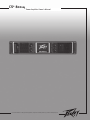
Peavey CS 800X4 User manual
- Category
- Musical Equipment
- Type
- User manual
This manual is also suitable for

For more information on other great Peavey products, visit your local Peavey dealer or go online to www.peavey.com
Power Amplifier Owner's Manual
CS
®
800x
4
Page is loading ...

3
IMPORTANT SAFETY INSTRUCTIONS
WARNING: When using electrical products, basic cautions should always be followed, including the following:
1. Read these instructions.
2. Keep these instructions.
3. Heed all warnings.
4. Follow all instructions.
5. Do not use this apparatus near water.
6. Clean only with a dry cloth.
7. Do not block any of the ventilation openings. Install in accordance with manufacturer’s instructions.
8. Do not install near any heat sources such as radiators, heat registers, stoves or other apparatus (including amplifiers)
that produce heat.
9. Do not defeat the safety purpose of the polarized or grounding-type plug. A polarized plug has two blades with one
wider than the other. A grounding type plug has two blades and a third grounding plug. The wide blade or third prong is
provided for your safety. If the provided plug does not fit into your outlet, consult an electrician for replacement of the
obsolete outlet.
10. Protect the power cord from being walked on or pinched, particularly at plugs, convenience receptacles, and the point
they exit from the apparatus.
11. Note for UK only: If the colors of the wires in the mains lead of this unit do not correspond with the terminals in your
plug‚ proceed as follows:
a) The wire that is colored green and yellow must be connected to the terminal that is marked by the letter E‚ the earth
symbol‚ colored green or colored green and yellow.
b) The wire that is colored blue must be connected to the terminal that is marked with the letter N or the color black.
c) The wire that is colored brown must be connected to the terminal that is marked with the letter L or the color red.
12. Only use attachments/accessories provided by the manufacturer.
13. Use only with a cart, stand, tripod, bracket, or table specified by the manufacturer, or sold with the apparatus. When a
cart is used, use caution when moving the cart/apparatus combination to avoid injury from tip-over.
14. Unplug this apparatus during lightning storms or when unused for long periods of time.
15. Refer all servicing to qualified service personnel. Servicing is required when the apparatus has been damaged in any
way, such as power-supply cord or plug is damaged, liquid has been spilled or objects have fallen into the apparatus,
the apparatus has been exposed to rain or moisture, does not operate normally, or has been dropped.
16. Never break off the ground pin. Write for our free booklet “Shock Hazard and Grounding.” Connect only to a power
supply of the type marked on the unit adjacent to the power supply cord.
17. If this product is to be mounted in an equipment rack, rear support should be provided.
18. Exposure to extremely high noise levels may cause a permanent hearing loss. Individuals vary considerably in suscep
-
tibility to noise-induced hearing loss, but nearly everyone will lose some hearing if exposed to sufficiently intense noise
for a sufficient time. The U.S. Government’s Occupational Safety and Health Administration (OSHA) has specified the
following permissible noise level exposures:
Duration Per Day In Hours Sound Level dBA, Slow Response
8 90
6 92
4 95
3 97
2 100
1 1⁄2 102
1 105
1⁄2 110
1⁄4 or less 115
According to OSHA, any exposure in excess of the above permissible limits could result in some hearing loss. Ear plugs or protectors to
the ear canals or over the ears must be worn when operating this amplification system in order to prevent a permanent hearing loss, if
exposure is in excess of the limits as set forth above. To ensure against potentially dangerous exposure to high sound pressure levels, it is
recommended that all persons exposed to equipment capable of producing high sound pressure levels such as this amplification system be
protected by hearing protectors while this unit is in operation.
SAVE THESE INSTRUCTIONS!
Page is loading ...
Page is loading ...
Page is loading ...

7
CS
®
800x
4
Power Amplifier
Congratulations on your purchase of a Peavey CS Series power amplifier! Designed for years of reliable operation, CS Series
amplifiers offer the sonic superiority and unsurpassed reliability for which Peavey is famous in a rugged, compact unit.
Advanced technologies and extensive protection circuitry allow operation with greater efficiency, even under difficult loads
and power conditions. The DDT
™
(Distortion Detection Technique) circuit ensures trouble-free operation into loads as low as 2
ohms, protects speakers and ensures sonic integrity even in extreme overload conditions. Peavey’s high-efficiency design uses
tunnel-cooled heat sinks and dual-speed DC fans for consistent lower overall operating temperature, resulting in longer output
transistor life.
Peavey CS Series amplifiers are simple to operate and housed in ultra-strong steel chassis, but improper use can be
dangerous. Some CS Series amplifiers are very high powered and can put out high voltages and sizable currents at frequencies
up to 30 kHz. Always use safe operating techniques with these amplifiers.
FOR YOUR SAFETY, READ THE IMPORTANT PRECAUTIONS SECTION, AS WELL AS INPUT, OUTPUT AND POWER
CONNECTION SECTIONS.
Unpacking
Upon unpacking, inspect the amplifier. If you find any damage, notify your supplier immediately. Only the consignee
(the supplier from whom you purchased the amplifier) may institute a claim with the carrier for damage incurred
during shipping. Be sure to save the carton and all packing materials. Should you ever need to ship the unit back to
Peavey or one of its offices, service centers or the supplier, use only the original factory packing. If the shipping carton
is unavailable, contact Peavey to obtain a replacement.
Mounting
CS Series amplifiers will mount in standard 19" racks. Rear mounting ears are also provided for additional support,
which is recommended in non-permanent installations like mobile or touring sound systems. Because of the cables
and connectors on the rear panel, a right angle or offset screwdriver or hex key will make it easier to fasten the rear
mounting ears to the rails.
Cooling Requirements
CS 800
x
4
amplifier uses a forced-air cooling system to maintain a low, consistent operating temperature. Air is drawn
into the amplifier by a fan on the back panel and courses through the cooling fins of the tunnel-configured channel
heat sink, then exhausts through the front panel grille. If the heat sink gets too hot, sensing circuits will open the
output relays for the hot channels, disconnecting the load for those channels. It is important to have an air inlet at the
back of the amplifier to allow cooling air to enter. If the amp is rack mounted, do not use doors or covers on the back
of the rack, as the intake air must flow without resistance. Make sure that there is one (1) standard rack space opening
for every three mounted power amplifiers.
ENGLISH

8
Operating Precautions
Make sure the mains voltage is correct and the same as that printed on the rear of the amplifier. Damage caused by
connecting the amplifier to improper AC voltage is not covered by any CS
®
Series warranty. See the Connecting Power
section for more information on voltage requirements.
Note: Always turn off and disconnect the amplifier from mains voltage before making audio connections. Also, as an
extra precaution, have the attenuators turned down during power-up.
Before powering up, turn the attenuator controls down to prevent speaker damage if there is a high signal level at the
inputs. Always use high-quality input and speaker cables to ensure trouble-free operation. Most intermittent problems
are caused by faulty cables.
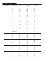
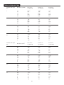
Consult the Wire Gauge Charts (page 9) to determine proper gauges for differing load impedances and cable lengths.
Cable resistance robs amplifier power in two ways: power lost directly to resistance (I
2
R loss) and by increasing the
impedance of the load presented to the amplifier, thereby decreasing the power demanded of the amplifier.
Connecting Inputs
Input connections are made via the three-pin XLR (pin 2+) or 6.3 mm plug “combi” connectors on the rear panel of the
amplifier. The inputs are actively balanced and the overload point is high enough to accept the maximum output level
of virtually any signal source.
Connecting Outputs
The CS 800
x
4
has one Speakon
®
connector per channel. The connectors for channels 1 and 3 include the output of
channels 2 and 4 to facilitate Bridged mode operation.
Connecting Power
CS Series amplifier power requirements are rated at 1/8 power (typical music conditions) and 1/3 power (extreme
music conditions). The maximum power current draw rating is limited only by the front panel circuit breaker. Consult
the specifications in the Appendices section for figures on the current that each amplifier will demand. Unless
otherwise specified when ordered, Peavey amplifiers shipped to customers are configured as follows:
North America - 120VAC/60Hz
Europe, Asia, Australia - 230/240VAC/60-50Hz
South America - 120VAC/60Hz or 240VAC/50Hz
Note: Always turn off and disconnect the amplifier from mains voltage before making audio connections. As an extra
precaution, have the attenuators turned down while powering up.
Introduction
WARNING
THE ON/OFF SWITCH IN THIS APPARATUS
DOES NOT BREAK BOTH SIDES OF THE MAINS.
HAZARDOUS ENERGY MAY BE
PRESENT INSIDE
THE ENCLOSURE WHEN THE POWER SWITCH IS
IN THE OFF POSITION.

9
Stranded Cable Lgth.
(m)
2
5
10
30
Wire Gauge (mm
2
)
0.3
0.5
0.75
1.5
2.5
4
0.5
0.75
1.5
2.5
4
6
0.5
0.75
1.5
2.5
4
6
0.75
1.5
2.5
4
6
10
Power Loss
(8 ohm load)
2.9%
1.74
1.16
0.58
0.35
0.22
4.3%
2.9
1.45
0.87
0.55
0.37
8.24%
5.6
2.9
1.74
1.09
0.73
15.5%
8.2
5.1
3.2
2.2
1.31
Power Loss
(4 ohm load)
5.6%
3.4
2.3
1.16
0.70
0.44
8.2%
5.6
2.9
1.74
1.09
0.73
15.5%
10.8
5.6
2.9
1.74
1.09
25%
15.5
9.8
6.3
4.3
2.6
Power Loss
(2 ohm load)
10.8%
6.7
4.5
2.3
1.39
0.87
15.5%
10.8
5.6
3.4
2.2
1.45
28%
19.9
10.8
6.7
4.3
2.9
45%
28
18.2
12.0
8.2
5.1
Stranded Cable Lgth.
(ft.)
5
10
40
80
Wire Gauge (AWG)
18
16
14
12
10
18
16
14
12
10
18
16
14
12
10
8
18
16
14
12
10
8
Power Loss
(8 ohm load)
0.81%
0.51
0.32
0.20
0.128
1.61%
1.02
0.64
0.40
0.25
6.2%
4.0
2.5
1.60
1.01
0.60
11.9%
7.7
5.0
3.2
2.0
1.20
Power Loss
(4 ohm load)
1.61%
1.02
0.64
0.40
0.25
3.2%
2.0
1.28
0.80
0.51
11.9%
7.7
5.0
3.2
2.0
1.20
22%
14.6
9.6
6.2
4.0
2.4
Power Loss
(2 ohm load)
3.2%
2.0
1.28
0.80
0.51
6.2%
4.0
2.5
1.60
1.01
22%
14.6
9.6
6.2
4.0
2.4
37%
26
17.8
11.8
7.7
4.7
Wire Gauge Charts

10
Stereo Operation
For stereo (dual channel) operation, turn the amplifier OFF and set the mode select switches to the stereo position. In
this mode, the respective channels operate independently of each other, with their input attenuators controlling their
respective levels. Thus, a signal at channel 1's input produces an amplified signal at channel 1's output, while a signal
at channel 2's input produces an amplified signal at channel 2's output. The same applies to channels 3 and 4 when
their respective mode switch is in the Stereo position.
Parallel Operation
For parallel operation (dual-channel operation through one input), turn the amplifier OFF and set the mode switch to
the Parallel position; both amplifier channels are then driven by the signal at channel 1's input (no jumper wires are
required). Output connections are the same as in Stereo mode. In Parallel mode, the input connectors on channel
1 and channel 2 are strapped together to allow patching to another amplifier or to channels 3 or 4. Both input
attenuators remain active, allowing you to set different levels for each channel. Power and other general performance
specifications are the same as in Stereo mode. The same applies to channels 3 and 4 when their respective mode
switch is in the Parallel position; the input connectors on channels 3 and 4 are strapped together to allow patching to
another amplifier.
Bridged Mono Operation
Two amplifier channels (1 and 2 or 3 and 4, respectively), can be bridged together to make a very powerful single-
channel monaural amplifier. Use extreme caution when operating in Bridged mode; potentially lethal voltage may be
present at the output terminals. To bridge the amplifier, slide the rear panel amplifier mode select switch to the Bridge
position. Direct the signal to channel 1's input and connect the speakers across the hot outputs (the “1+POS” and
“2+NEG” Speakon
®
connector) for channel 1. As with Parallel mode, both input connectors are strapped together to
drive the input of another amplifier. The same applies to channels 3 and 4. Connect the speakers across the “1+POS”
and “2+NEG” Speakon connector for channel 3.
When operating in the bridged mode, both attenuators of a respective set of channels (i.e. channel 1 and 2 or 3 and 4)
must be in the same position so the speaker load will be equally shared between the channels.
Unlike Stereo and Parallel modes, in which one side of each output is at ground, both sides are hot in Bridged mode.
Channel 1's side is the same polarity as its input with the minimum nominal load impedance being 4 ohms (equivalent
to driving both channels at 2 ohms) in Bridged mode. Driving bridged loads of less than 4 ohms will activate the
DDT™ circuitry, resulting in a loss of power, and may also cause a thermal (overheating) overload.
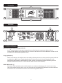
Operation Modes

Front Panel
11
AC Power Circuit Breakers (1)
The CS
®
800x
4
amplifier has two circuit breakers on the back panel. If circuit breaker shuts off during normal use,
push it back to the ON position once. If it will not stay ON, the amplifier needs servicing.
Input Attenuators (2)
Whenever possible, set the attenuators fully clockwise to maintain optimum system headroom. The four input
attenuator controls located at the front panel decrease gain (signal level) for the respective amplifier channels in all
modes. See the specifications at the end of this manual for standard voltage gain and input sensitivity information.
Mode Select Switch (3)
When operating in Bridged mode, both attenuators of a respective set of channels (i.e. channels 1 and 2 or 3 and 4)
must be in the same position so the speaker load will be equally shared between the channels. See the section on
Bridged Mono Operation for more information and precautions.
Switches & Controls
Rear Panel
1
2
2
3

12
CS
®
Series amplifiers feature three front panel LED indicators per channel: PWR (power), SIG (signal), and DDT
™
(Distortion
Detection Technique). These LED indicators inform the user of each channel’s operating status and warn of possible abnormal
conditions.
PWR LED (1)
The Power LED indicates that its channel’s output relay is closed and the channel is operational.
SIG LED (2)
The Signal LED illuminates when its channel produces an output signal of greater than 1 volt RMS or 25 mV input
with a 0 dB attenuation of the front panel knobs. This is useful in determining whether a signal is reaching and being
amplified by the amplifier. If the Signal LED is illuminated but no sound is present, that means a signal is present at
the amplifier but a problem may exist after the amplifier, such as in the cables or speakers.
DDT LED (3)
A channel’s DDT LED will illuminate at the onset of clipping. If the LEDs are flashing quickly and intermittently, the
channel is just at the clip threshold, while a steady, bright glow means the amp is clip limiting, or reducing gain to
prevent severely clipped waveforms from reaching the speakers. See Distortion Detection Technique Limiting under
the Protection Features section for more information.
Indicators
Front Panel
1 1
1 1
2
2
2
2
3
3
3
3

13
The CS
®
800x
4
amplifier incorporates several circuits to protect both itself and loudspeakers under virtually any
situation. Peavey has made this amplifier as foolproof as possible by making it immune to short and open circuits,
mismatched loads, DC voltage and overheating. If a channel goes into the DDT™ gain reduction mode, the DDT LED
illuminates. The speaker load remains connected, but clipping percentage or output power is instantly reduced. When
a problem occurs that causes a channel to go into a protection mode, the PWR (Power) LED for that channel will turn
off. DC voltage on the output, excessive subsonic frequencies, or thermal overload will cause the channel’s output
relay to disconnect the speaker load until the problem is corrected or the amplifier cools down.
Distortion Detection Technique (DDT) Limiting
Any time a channel is driven into hard, continuous clipping, the DDT circuit will automatically reduce the channel gain
to a level just slightly into clipping, guarding the speakers against the damaging, high-power, continuous square
waves that may be produced. Situations that may activate the DDT circuit include uncontrolled feedback, oscillations,
an improper equipment setting or malfunction upstream from the amplifier. Normal program transients will not trigger
DDT; only steady, excessive clipping will cause the DDT LED to illuminate.
LFC Impedance Sensing
The CS
800x
4
amplifier features innovative circuitry for safe operation into any load. When an amplifier senses a load
that overstresses the output stage, the Load Fault Correction circuit adjusts the channel gain to a safe level. Extreme
load fault under high power levels will cause the signal to be muted for the associated channel. This method of output
stage protection is far more effective than the standard limiting found on conventional power amplifiers. The LFC
circuit is sonically transparent in normal use and unobtrusive when activated.
Thermal Protection
The internal fan will keep the amplifier operating well within its intended temperature range under all normal
conditions. If the heat sink temperature reaches 85°C, which may indicate an obstructed air supply, the channels will
protect themselves by disconnecting their load and shutting down until the heat sink has cooled. During this time, the
PWR LED will go out, the DDT LED will stay lit and the cooling fan will continue operating at high speed.
Short Circuit
If an output is shorted, the LFC and thermal circuits will automatically protect the amplifier. The LFC circuit senses
the short circuit as an extremely stressful load condition and attenuates the signal, protecting the channel’s output
transistors from over current stress. If the short circuit remains, the amplifier will eventually thermally protect itself by
opening both channel speaker relays, disconnecting the loads until the heat sink cools down.
DC Voltage Protection
If an amplifier channel detects DC voltage or subsonic frequencies at its output terminals, its speaker relay opens and
disconnects the load to prevent speaker damage.
Turn-On/Turn-Off Protection
Upon powering-up, the amplifier mutes the input signals and stays in Protect mode with the speaker connect relays
open for approximately four seconds. This allows the internal power supplies to charge and the amplifier to stabilize.
After the relays engage, the signals slowly increase the muted signals to their normal level. Also, when power is
removed, the input signals are muted so that no thumps or pops are heard.
Protection Features

14
RampUp
™
Signal Control
Whenever the CS
®
800x
4
amplifier powers up or comes out of a protect mode, the RampUp circuit activates. While the
speakers are disconnected, the RampUp circuit fully attenuates the signal and activates the DDT LED. After the output
relay closes, the signal slowly and gradually raises to its set level. The PWR LED will illuminate and the DDT LED will
turn off when the signal is no longer attenuated. The RampUp Signal Control circuit has some important advantages
over the conventional instant-on circuits:
1. If a signal is present during power-up (or when coming out of protect), the speakers are spared a sudden,
potentially damaging burst of audio power.
2. Because the gain is reduced until after the output relay closes, no arcing occurs at the contacts, thereby
extending their useful life.
All loudspeakers have electrical, thermal and physical limits that must be observed to prevent damage or failure. Excessive
power, low frequencies applied to high frequency drivers, severely clipped waveforms and DC voltage can all be fatal to cone
and compression drivers. Peavey CS
®
Series amplifiers automatically protect speakers from DC voltages and subsonic signals.
If using an electronic crossover, be extremely careful that the low and mid bands are connected to the correct amplifiers and
drivers and not to those designed for a higher frequency band. An amplifier’s clipping point is its maximum peak output power,
and some of the higher powered Peavey CS Series amplifiers can deliver more power than many speakers can safely handle. Be
sure the peak power capability of the amplifier is not excessive for your speaker system. For more information, see the section
on Protection Features.
Fuses may also be used to limit power to speaker drivers, although as current-limiting rather than voltage-limiting devices, they
are an imperfect solution, and as the weakest links, they only limit once before needing replacement. Some poor-quality fuses
have a significant series resistance that could degrade the amplifier’s damping of the speaker’s motion and may even deterio
-
rate the system’s sound quality. If you elect to use fuses, check with the speaker manufacturer to determine the proper current
rating and time lag required.
Do not drive any low frequency speaker enclosure with frequencies lower than its own tuned frequency; the reduced acousti
-
cal damping could cause a ported speaker to bottom out even at moderate power. Consult the speaker system specifications to
determine its frequency limits.
Speaker Protection
Protection Features

15
The CS
®
800x
4
amplifier requires no routine maintenance and should not need internal adjustment during its lifetime. Your CS
800x4 amplifier is very powerful and can be potentially dangerous to loudspeakers and humans alike. It is your responsibil-
ity to read the Important Precautions section and to make sure that the amplifier is installed, wired and operated properly as
instructed in this manual. Many loudspeakers can be easily damaged or destroyed by overpowering, especially with the high
power available from a bridged amplifier. Read the Speaker Protection section and always be aware of the speaker’s continuous
and peak power capabilities.
In the unlikely event that your amplifier develops a problem, it must be returned to an authorized distributor, service center or
shipped directly to our factory. To obtain service, contact your nearest Peavey Service Center, Distributor, Dealer, or any of the
worldwide Peavey offices. For contact information, reach Peavey Inc. Customer Service directly:
Telephone: 601-483-5365 (USA)
Fax Number: 601-486-1278 (USA)
For technical inquiries only, the Peavey Technical Services department can be faxed at 601-486-1361 (USA)
Because of the complexity of the design and risk of electrical shock, all repairs
must be performed only by qualified technical
personnel. If the unit needs to be shipped back to the factory, it must be sent in its original carton. It is the responsibility of the
person shipping the unit to properly package the amplifier. If you need a product shipping carton, please contact Peavey for a
replacement.
Please visit the Peavey website at: http://www.peavey.com.
Amplifier Maintenance and User Responsiblity
Service / Warranty Information

16
CS
®
800x4
Power Amplifier
SPECIFICATIONS
CS 800x4
Rated Power 4 ohms bridged
825 watts @ 1 kHz <0.025% THD
Rated Power 4 x 2 ohms
400 watts per channel @ 1 kHz <0.025% THD four channels driven
Rated Power 4 x 4 ohms
300 watts per channel @ 1 kHz <0.02% THD four channels driven
Rated Power 4 x 8 ohms
180 watts per channel @ 1 kHz <0.02% THD four channels driven
Rated Power 1 x 2 ohms
500 watts @ 1 kHz at <0.02% THD
Rated Power 1 x 4 ohms
350 watts @ 1 kHz at <0.015% THD
Rated Power 1 x 8 ohms
200 watts @ 1 kHz at <0.006% THD
Minimum Load Impedance
2 ohms
Maximum RMS Voltage Swing
45 volts
Frequency Response
10 Hz - 20 kHz; +0, -1 dB at 1 watt
Power Bandwidth
10 Hz - 50 kHz; +0, -3 dB at rated 2 ohms power
T.H.D. 4 x 2 ohms
<0.20% @ 325 W per channel from 20 Hz to 20 kHz
T.H.D. 4 x 4 ohms
<0.10% @ 250 W per channel from 20 Hz to 20 kHz
T.H.D. 4 x 8 ohms
<0.10% @ 160 W per channel from 20 Hz to 20 kHz
SMPTE IMD
<0.1% 60 Hz and 7 kHz, 250 W @ 4 ohms
Slew Rate
7 V/us
Damping Factor (8 ohms)
> 400:1 @ 20 Hz - 400 Hz
Input CMRR
> -93 dB @ 1 kHz
Voltage Gain
x 40 (32 dB)
Input Sensitivity
0.720 V @ 2 ohms, 0.865 V @ 4 ohms, 0.940 V @ 8 ohms
Input Impedance
15k ohms, balanced
Hum and Noise
> -108 dB, “A” weighted referenced to rated 4 ohms power

17
CS
®
800x4
Power Amplifier
SPECIFICATIONS
CS 800x4
Crosstalk
> -60 dB, “A” weighted referenced to rated 4 ohms power
Current Draw @ 1/8 Power
930 watts @ 2 ohms, 640 watts @ 4 ohms, 420 watts @ 8 ohms
Current Draw @ 1/3 Power
1995 watts @ 2 ohms, 1365 watts @ 4 ohms, 795 watts @ 8 ohms
Idle Current Draw
60 watts
Cooling
80 mm DC fan, off until heat sink reaches 45° C, then variable speed
Controls
4 attenuators, 2 mode select switches
Indicator LEDs
4 DDT™, 4 Power/Status, 4 Signal Present
Protection
Temp, DC, turn-on transients, improper load or shorts
Connectors
Combi XLR & 6.3 mm input, Speakon
®
and Binding Post speaker output, IEC
mains connector
Construction
16 ga. steel with cast aluminum front panel and steel grille
Dimensions
88.9 mm x 482.6 mm x 376.3 mm + 31.8 mm for rear support ears and
connectors
(3.5” x 19” x 14.81” + 1.25”) + 1.5” for handle depth
Gross Weight
43.5 lbs. (19.73 kg.)
Net Weight
38.3 lbs. (17.37kg.)
Page is loading ...
Page is loading ...

20
Stranded Cable Lgth.
(m)
2
5
10
30
Wire Gauge (mm
2
)
0.3
0.5
0.75
1.5
2.5
4
0.5
0.75
1.5
2.5
4
6
0.5
0.75
1.5
2.5
4
6
0.75
1.5
2.5
4
6
10
Power Loss
(8 ohm load)
2.9%
1.74
1.16
0.58
0.35
0.22
4.3%
2.9
1.45
0.87
0.55
0.37
8.24%
5.6
2.9
1.74
1.09
0.73
15.5%
8.2
5.1
3.2
2.2
1.31
Power Loss
(4 ohm load)
5.6%
3.4
2.3
1.16
0.70
0.44
8.2%
5.6
2.9
1.74
1.09
0.73
15.5%
10.8
5.6
2.9
1.74
1.09
25%
15.5
9.8
6.3
4.3
2.6
Power Loss
(2 ohm load)
10.8%
6.7
4.5
2.3
1.39
0.87
15.5%
10.8
5.6
3.4
2.2
1.45
28%
19.9
10.8
6.7
4.3
2.9
45%
28
18.2
12.0
8.2
5.1
Stranded Cable Lgth.
(ft.)
5
10
40
80
Wire Gauge (AWG)
18
16
14
12
10
18
16
14
12
10
18
16
14
12
10
8
18
16
14
12
10
8
Power Loss
(8 ohm load)
0.81%
0.51
0.32
0.20
0.128
1.61%
1.02
0.64
0.40
0.25
6.2%
4.0
2.5
1.60
1.01
0.60
11.9%
7.7
5.0
3.2
2.0
1.20
Power Loss
(4 ohm load)
1.61%
1.02
0.64
0.40
0.25
3.2%
2.0
1.28
0.80
0.51
11.9%
7.7
5.0
3.2
2.0
1.20
22%
14.6
9.6
6.2
4.0
2.4
Power Loss
(2 ohm load)
3.2%
2.0
1.28
0.80
0.51
6.2%
4.0
2.5
1.60
1.01
22%
14.6
9.6
6.2
4.0
2.4
37%
26
17.8
11.8
7.7
4.7
Kabelstärkentabellen
Page is loading ...
Page is loading ...
Page is loading ...
Page is loading ...
Page is loading ...
Page is loading ...
Page is loading ...
Page is loading ...
Page is loading ...
Page is loading ...

31
Stranded Cable Lgth.
(m)
2
5
10
30
Wire Gauge (mm
2
)
0.3
0.5
0.75
1.5
2.5
4
0.5
0.75
1.5
2.5
4
6
0.5
0.75
1.5
2.5
4
6
0.75
1.5
2.5
4
6
10
Power Loss
(8 ohm load)
2.9%
1.74
1.16
0.58
0.35
0.22
4.3%
2.9
1.45
0.87
0.55
0.37
8.24%
5.6
2.9
1.74
1.09
0.73
15.5%
8.2
5.1
3.2
2.2
1.31
Power Loss
(4 ohm load)
5.6%
3.4
2.3
1.16
0.70
0.44
8.2%
5.6
2.9
1.74
1.09
0.73
15.5%
10.8
5.6
2.9
1.74
1.09
25%
15.5
9.8
6.3
4.3
2.6
Power Loss
(2 ohm load)
10.8%
6.7
4.5
2.3
1.39
0.87
15.5%
10.8
5.6
3.4
2.2
1.45
28%
19.9
10.8
6.7
4.3
2.9
45%
28
18.2
12.0
8.2
5.1
Stranded Cable Lgth.
(ft.)
5
10
40
80
Wire Gauge (AWG)
18
16
14
12
10
18
16
14
12
10
18
16
14
12
10
8
18
16
14
12
10
8
Power Loss
(8 ohm load)
0.81%
0.51
0.32
0.20
0.128
1.61%
1.02
0.64
0.40
0.25
6.2%
4.0
2.5
1.60
1.01
0.60
11.9%
7.7
5.0
3.2
2.0
1.20
Power Loss
(4 ohm load)
1.61%
1.02
0.64
0.40
0.25
3.2%
2.0
1.28
0.80
0.51
11.9%
7.7
5.0
3.2
2.0
1.20
22%
14.6
9.6
6.2
4.0
2.4
Power Loss
(2 ohm load)
3.2%
2.0
1.28
0.80
0.51
6.2%
4.0
2.5
1.60
1.01
22%
14.6
9.6
6.2
4.0
2.4
37%
26
17.8
11.8
7.7
4.7
La Charte De Dimensions Des Cables
Page is loading ...
Page is loading ...
Page is loading ...
Page is loading ...
Page is loading ...
Page is loading ...
Page is loading ...

39
CS
®
800x4
Power Amplifier
SPECIFICATIONS
CS 800x4
Influence inter-canal
> -60 dB, “A” (référence pondérée à la puissance 4 ohms)
Consommation électrique @ 1/8
de la puissance
930 watts @ 2 ohms, 640 watts @ 4 ohms, 420 watts @ 8 ohms
Consommation électrique @ 1/3
de la puissance
1995 watts @ 2 ohms, 1365 watts @ 4 ohms, 795 watts @ 8 ohms
Consommation électrique au
repos
60 watts
Refroidissement
Ventilateur 80 mm DC, coupé jusqu’à une température de radiateur de 45° C,
puis à vitesse variable
Contrôles
4 atténuateurs, 2 sélecteurs de mode
Indicateur LEDs
4 DDT™, 4 Alimentation/Status, 4 Présence de Signal
Protection
Temp, DC, turn-on transients, improper load or shorts
Connecteurs
Combi XLR & 6.3 mm input, Speakon
®
and Binding Post speaker output, IEC
mains connector
Construction
16 ga. Acier avec façade avant et grille aluminiuml
Dimensions
88.9 mm x 482.6 mm x 376.3 mm + 31.8 mm pour le support Rack arrière et
connecteurs
(3.5” x 19” x 14.81” + 1.25”) + 1.5” de profondeur de poignée
Poids
43.5 lbs. (19.73 kg.)
Poids net
38.3 lbs. (17.37kg.)
Page is loading ...
Page is loading ...

42
Stranded Cable Lgth.
(m)
2
5
10
30
Wire Gauge (mm
2
)
0.3
0.5
0.75
1.5
2.5
4
0.5
0.75
1.5
2.5
4
6
0.5
0.75
1.5
2.5
4
6
0.75
1.5
2.5
4
6
10
Power Loss
(8 ohm load)
2.9%
1.74
1.16
0.58
0.35
0.22
4.3%
2.9
1.45
0.87
0.55
0.37
8.24%
5.6
2.9
1.74
1.09
0.73
15.5%
8.2
5.1
3.2
2.2
1.31
Power Loss
(4 ohm load)
5.6%
3.4
2.3
1.16
0.70
0.44
8.2%
5.6
2.9
1.74
1.09
0.73
15.5%
10.8
5.6
2.9
1.74
1.09
25%
15.5
9.8
6.3
4.3
2.6
Power Loss
(2 ohm load)
10.8%
6.7
4.5
2.3
1.39
0.87
15.5%
10.8
5.6
3.4
2.2
1.45
28%
19.9
10.8
6.7
4.3
2.9
45%
28
18.2
12.0
8.2
5.1
Stranded Cable Lgth.
(ft.)
5
10
40
80
Wire Gauge (AWG)
18
16
14
12
10
18
16
14
12
10
18
16
14
12
10
8
18
16
14
12
10
8
Power Loss
(8 ohm load)
0.81%
0.51
0.32
0.20
0.128
1.61%
1.02
0.64
0.40
0.25
6.2%
4.0
2.5
1.60
1.01
0.60
11.9%
7.7
5.0
3.2
2.0
1.20
Power Loss
(4 ohm load)
1.61%
1.02
0.64
0.40
0.25
3.2%
2.0
1.28
0.80
0.51
11.9%
7.7
5.0
3.2
2.0
1.20
22%
14.6
9.6
6.2
4.0
2.4
Power Loss
(2 ohm load)
3.2%
2.0
1.28
0.80
0.51
6.2%
4.0
2.5
1.60
1.01
22%
14.6
9.6
6.2
4.0
2.4
37%
26
17.8
11.8
7.7
4.7
Tablas de Calibre del Cable
Page is loading ...
Page is loading ...
Page is loading ...
Page is loading ...
Page is loading ...
Page is loading ...
Page is loading ...
Page is loading ...

51
PEAVEY ELECTRONICS CORPORATION LIMITED WARRANTY
Effective Date: July 1, 1998
What This Warranty Covers
Your Peavey Warranty covers defects in material and workmanship in Peavey products purchased and serviced in the U.S.A. and Canada.
What This Warranty Does Not Cover
The Warranty does not cover: (1) damage caused by accident, misuse, abuse, improper installation or operation, rental, product modification or neglect; (2) dam
-
age occurring during shipment; (3) damage caused by repair or service performed by persons not authorized by Peavey; (4) products on which the serial number
has been altered, defaced or removed; (5) products not purchased from an Authorized Peavey Dealer.
Who This Warranty Protects
This Warranty protects only the original retail purchaser of the product.
How Long This Warranty Lasts
The Warranty begins on the date of purchase by the original retail purchaser. The duration of the Warranty is as follows:
Product Category Duration
Guitars/Basses, Amplifiers, Pre-Amplifiers, Mixers, Electronic
Crossovers and Equalizers 2 years *(+ 3 years)
Drums 2 years *(+ 1 year)
Enclosures 3 years *(+ 2 years)
Digital Effect Devices and Keyboard and MIDI Controllers 1 year *(+ 1 year)
Microphones 2 years
Speaker Components (incl. speakers, baskets, drivers,
diaphragm replacement kits and passive crossovers)
and all Accessories 1 year
Tubes and Meters 90 days
[*Denotes additional warranty period applicable if optional Warranty Registration Card is completed and returned to Peavey by original retail purchaser within 90 days of pur-
chase.]
What Peavey Will Do
We will repair or replace (at Peavey's discretion) products covered by warranty at no charge for labor or materials. If the product or component must be shipped to
Peavey for warranty service, the consumer must pay initial shipping charges. If the repairs are covered by warranty, Peavey will pay the return shipping charges.
How To Get Warranty Service
(1) Take the defective item and your sales receipt or other proof of date of purchase to your Authorized Peavey Dealer or Authorized Peavey Service Center.
OR
(2) Ship the defective item, prepaid, to Peavey Electronics Corporation, International Service Center, 412 Highway 11 & 80 East, Meridian, MS 39301 or Peavey
Canada Ltd., 95 Shields Court, Markham, Ontario, Canada L3R 9T5. Include a detailed description of the problem, together with a copy of your sales receipt or
other proof of date of purchase as evidence of warranty coverage. Also provide a complete return address.
Limitation of Implied Warranties
ANY IMPLIED WARRANTIES, INCLUDING WARRANTIES OF MERCHANTABILITY AND FITNESS FOR A PARTICULAR PURPOSE, ARE LIMITED IN DURATION TO THE
LENGTH OF THIS WARRANTY.
Some states do not allow limitations on how long an implied warranty lasts, so the above limitation may not apply to you.
Exclusions of Damages
PEAVEY'S LIABILITY FOR ANY DEFECTIVE PRODUCT IS LIMITED TO THE REPAIR OR REPLACEMENT OF THE PRODUCT, AT PEAVEY'S OPTION. IF WE ELECT TO
REPLACE THE PRODUCT, THE REPLACEMENT MAY BE A RECONDITIONED UNIT. PEAVEY SHALL NOT BE LIABLE FOR DAMAGES BASED ON INCONVENIENCE, LOSS OF
USE, LOST PROFITS, LOST SAVINGS, DAMAGE TO ANY OTHER EQUIPMENT OR OTHER ITEMS AT THE SITE OF USE, OR ANY OTHER DAMAGES WHETHER INCIDENTAL,
CONSEQUENTIAL OR OTHERWISE, EVEN IF PEAVEY HAS BEEN ADVISED OF THE POSSIBILITY OF SUCH DAMAGES.
Some states do not allow the exclusion or limitation of incidental or consequential damages, so the above limitation or exclusion may not apply to you.
This Warranty gives you specific legal rights, and you may also have other rights which vary from state to state.
If you have any questions about this warranty or service received or if you need assistance in locating an Authorized Service Center, please contact the Peavey
International Service Center at (601) 483-5365 / Peavey Canada Ltd. at (905) 475-2578.
Features and specifications subject to change without notice.

Features and specifications subject to change without notice.
Peavey Electronics Corporation • 711 A Street • Meridian, MS 39301
(601) 483-5365 • FAX (601) 486-1278 • www.peavey.com
EX000015
© 2005
-
 1
1
-
 2
2
-
 3
3
-
 4
4
-
 5
5
-
 6
6
-
 7
7
-
 8
8
-
 9
9
-
 10
10
-
 11
11
-
 12
12
-
 13
13
-
 14
14
-
 15
15
-
 16
16
-
 17
17
-
 18
18
-
 19
19
-
 20
20
-
 21
21
-
 22
22
-
 23
23
-
 24
24
-
 25
25
-
 26
26
-
 27
27
-
 28
28
-
 29
29
-
 30
30
-
 31
31
-
 32
32
-
 33
33
-
 34
34
-
 35
35
-
 36
36
-
 37
37
-
 38
38
-
 39
39
-
 40
40
-
 41
41
-
 42
42
-
 43
43
-
 44
44
-
 45
45
-
 46
46
-
 47
47
-
 48
48
-
 49
49
-
 50
50
-
 51
51
-
 52
52


Peavey CS 800X4 User manual
- Category
- Musical Equipment
- Type
- User manual
- This manual is also suitable for
Ask a question and I''ll find the answer in the document
Finding information in a document is now easier with AI
in other languages
- français: Peavey CS 800X4 Manuel utilisateur
- español: Peavey CS 800X4 Manual de usuario
- Deutsch: Peavey CS 800X4 Benutzerhandbuch
Related papers
-
Peavey IPR 3000 User manual
-
-
-
Peavey PV 20 User manual
-
-
-
-
-
 Peavy CS 1400 Power Amplifier User manual
-

Other documents
-
Crest Audio CC 4000 User manual
-
 Architectural Acoustics IP-Six User manual
-
Crest Audio CLh 5000 User manual
-
 Architectural Acoustics IP-Six User manual
-
-
Yamaha P2075 Owner's manual
-
RCS DBA-500DPN Owner's manual
-
-
Pyle PTA1000 User manual
-

